
Owners Manual
Page 1
All rights reserved. 1 Owner's Manual SmartOnline® SUTX 3-Phase UPS System 20/40kVA Models: SUTX20K, SUTX40K Input: 220/230/240V (Ph-N) 380/400/415V (Ph-Ph), 3ph 4-Wire + PE 1111 W. 35th Street, Chicago, IL 60609 USA • www.tripplite.com/support Copyright © 2016 Tripp Lite.
All rights reserved. 1 Owner's Manual SmartOnline® SUTX 3-Phase UPS System 20/40kVA Models: SUTX20K, SUTX40K Input: 220/230/240V (Ph-N) 380/400/415V (Ph-Ph), 3ph 4-Wire + PE 1111 W. 35th Street, Chicago, IL 60609 USA • www.tripplite.com/support Copyright © 2016 Tripp Lite.

Owners Manual
Page 3
... are visible via Tripp Lite's free PowerAlert® power management software. The UPS continuously conditions the incoming electrical power supply, eliminating power fluctuations and interruptions that will otherwise damage sensitive electronic devices and cause system downtime. Introduction Tripp Lite's SmartOnline SUTX Series Uninterruptible Power Supply (UPS) is linked to conveniently set parameters for accurate, clear monitoring • Serial, USB and volt...
... are visible via Tripp Lite's free PowerAlert® power management software. The UPS continuously conditions the incoming electrical power supply, eliminating power fluctuations and interruptions that will otherwise damage sensitive electronic devices and cause system downtime. Introduction Tripp Lite's SmartOnline SUTX Series Uninterruptible Power Supply (UPS) is linked to conveniently set parameters for accurate, clear monitoring • Serial, USB and volt...

Owners Manual
Page 4
...on the batteries to take adequate measures. • Use of this equipment in which case, the user is disconnected from the mains. Wear insulating gloves and boots. 4. Contact Tripp Lite for ...INSTRUCTIONS This manual contains instructions and warnings that may cause radio interference, in life support applications where failure of the batteries. • A battery can connect with insulated handles. 3. To avoid risk of batteries: 1. For relevant information, refer to 3.6.1 Precautions Prior to Wiring. • The protective devices connecting to the UPS must be installed...
...on the batteries to take adequate measures. • Use of this equipment in which case, the user is disconnected from the mains. Wear insulating gloves and boots. 4. Contact Tripp Lite for ...INSTRUCTIONS This manual contains instructions and warnings that may cause radio interference, in life support applications where failure of the batteries. • A battery can connect with insulated handles. 3. To avoid risk of batteries: 1. For relevant information, refer to 3.6.1 Precautions Prior to Wiring. • The protective devices connecting to the UPS must be installed...
Owners Manual
Page 5
... temperature is in bypass mode, disconnect the UPS from the utility power, open the internal battery fuse holders (refer to be placed in a dry and well-ventilated area at a temperature between -15°C and 40°C. To turn off the UPS,...battery cabinet grounding 18 Positive battery terminal 19 Negative battery terminal 5 Symbol Description 1 NORMAL Online mode LED indicator: green 2 BATTERY Battery mode LED indicator: yellow 3 BYPASS Bypass mode LED indicator: yellow 4 FAULT Fault LED indicator: red 5 ON ON key 6 OFF OFF key 7 ESC Goes back to installation...
... temperature is in bypass mode, disconnect the UPS from the utility power, open the internal battery fuse holders (refer to be placed in a dry and well-ventilated area at a temperature between -15°C and 40°C. To turn off the UPS,...battery cabinet grounding 18 Positive battery terminal 19 Negative battery terminal 5 Symbol Description 1 NORMAL Online mode LED indicator: green 2 BATTERY Battery mode LED indicator: yellow 3 BYPASS Bypass mode LED indicator: yellow 4 FAULT Fault LED indicator: red 5 ON ON key 6 OFF OFF key 7 ESC Goes back to installation...

Owners Manual
Page 6
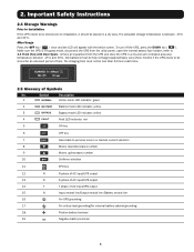
...installation. 6 Internal 1. The balance supports have been locked on the top of the factory. 2. An authorized Tripp Lite engineer must perform the startup of the UPS and a completed start-up form must be returned, carefully repack the UPS and all of the accessories using the original packing 5 material that came with internal batteries) 2 Owner's Manual 3 Test Card 4 Battery...the device number and capacity match what you ordered. 2 3 4 2. Important Safety Instructions 2.6 Standard Compliance This product meets the following safety standards and electromagnetic compatibility (EMC) ...
...installation. 6 Internal 1. The balance supports have been locked on the top of the factory. 2. An authorized Tripp Lite engineer must perform the startup of the UPS and a completed start-up form must be returned, carefully repack the UPS and all of the accessories using the original packing 5 material that came with internal batteries) 2 Owner's Manual 3 Test Card 4 Battery...the device number and capacity match what you ordered. 2 3 4 2. Important Safety Instructions 2.6 Standard Compliance This product meets the following safety standards and electromagnetic compatibility (EMC) ...
Owners Manual
Page 7
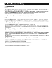
...not indicate any associated battery cabinets and all corridors, doors, gates, elevators, floors, etc. See Appendix 1 for input specifications. • Ensure the installation area has sufficient space for mounting on concrete or other equipment - Do not discard the balance supports, as a forklift; ...- Please consider the derating values when operating the UPS over long distance, use only. do not install and contact your local Tripp Lite representative. 3.4 Installation Environment • The UPS is sufficient to the utility. The UPS is suitable for maintenance and ventilation...
...not indicate any associated battery cabinets and all corridors, doors, gates, elevators, floors, etc. See Appendix 1 for input specifications. • Ensure the installation area has sufficient space for mounting on concrete or other equipment - Do not discard the balance supports, as a forklift; ...- Please consider the derating values when operating the UPS over long distance, use only. do not install and contact your local Tripp Lite representative. 3.4 Installation Environment • The UPS is sufficient to the utility. The UPS is suitable for maintenance and ventilation...

Owners Manual
Page 10
... bypass source. • The input of the UPS must be a Y connection, and the neutral line (N) must be changed to dual input or hot standby redundancy configuration, first contact qualified service personnel. Table 3-1: Specifications of input/output cables and circuit breakers, refer to the input and output of the UPS is suggested an installation transformer be installed...
... bypass source. • The input of the UPS must be a Y connection, and the neutral line (N) must be changed to dual input or hot standby redundancy configuration, first contact qualified service personnel. Table 3-1: Specifications of input/output cables and circuit breakers, refer to the input and output of the UPS is suggested an installation transformer be installed...

Owners Manual
Page 11
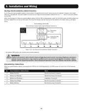
...T N INPUT BREAKER R S T N BYPASS BREAKER +N - 240V DC 240V DC BATTERY INPUT R S T N AC INPUT R S T N UPS OUTPUT + N - Installation and Wiring • The utility AC power must be three phases (R/S/T) and meet the specifications on the UPS rating label. Do not connect...battery terminal block. WARNING: 1. SUTX20K SUTX40K PARALLEL PARALLEL PARALLEL SWITCH RS-232 P1 P2 P3 P4 P5 P6 12 ON P1 P2 OUTPUT DRY CONTACT INPUT DRY CONTACT REPO CHARGER DETECTION MANUAL BYPASS SWITCH WARNING: OPENING THIS COVER PLATE WILL CAUSE INVERTER SHUTDOWN.ONLY AUTHORIZED SERVICE...
...T N INPUT BREAKER R S T N BYPASS BREAKER +N - 240V DC 240V DC BATTERY INPUT R S T N AC INPUT R S T N UPS OUTPUT + N - Installation and Wiring • The utility AC power must be three phases (R/S/T) and meet the specifications on the UPS rating label. Do not connect...battery terminal block. WARNING: 1. SUTX20K SUTX40K PARALLEL PARALLEL PARALLEL SWITCH RS-232 P1 P2 P3 P4 P5 P6 12 ON P1 P2 OUTPUT DRY CONTACT INPUT DRY CONTACT REPO CHARGER DETECTION MANUAL BYPASS SWITCH WARNING: OPENING THIS COVER PLATE WILL CAUSE INVERTER SHUTDOWN.ONLY AUTHORIZED SERVICE...

Owners Manual
Page 17
... UPS systems are as follows. 1 Follow steps 1 ~ 5 in bypass mode. 2. This ensures that the parallel UPS systems can be paralleled; 3....battery cabinet cables to the wiring terminal block and do not forget to ground the parallel UPS systems (refer to Figures 3-1~3-12/ 3-19). 3 Use the provided parallel cable to set ID (0, 1, 2 or 3) through the LCD. If the symbol '!' Installation...Diagram) 17 appears after an ID number, it indicates there is only one AC power source, parallel units' wiring procedures are paralleled, the length of parallel units, qualified service personnel should set...
... UPS systems are as follows. 1 Follow steps 1 ~ 5 in bypass mode. 2. This ensures that the parallel UPS systems can be paralleled; 3....battery cabinet cables to the wiring terminal block and do not forget to ground the parallel UPS systems (refer to Figures 3-1~3-12/ 3-19). 3 Use the provided parallel cable to set ID (0, 1, 2 or 3) through the LCD. If the symbol '!' Installation...Diagram) 17 appears after an ID number, it indicates there is only one AC power source, parallel units' wiring procedures are paralleled, the length of parallel units, qualified service personnel should set...

Owners Manual
Page 19
...bypass mode. 2. When wiring, connect the bypass source's R, S, T and N cables to the wiring terminal block. Only authorized Tripp Lite engineers or service personnel can modify single input/dual input setup. 2 Follow steps 1 ~ 5 in section 3.6.2 Single Unit Wiring. Before start-up of each unit's input cables/output cables must be equal. R S T N 240V DC 240V DC BATTERY... cannot be paralleled; If the symbol '!' 3. Installation and Wiring 2 After removing the panels, use the...3-13~3-18/3-20). 4 Use the provided parallel cable to set ID (0, 1, 2 or 3) through the LCD. See ...
...bypass mode. 2. When wiring, connect the bypass source's R, S, T and N cables to the wiring terminal block. Only authorized Tripp Lite engineers or service personnel can modify single input/dual input setup. 2 Follow steps 1 ~ 5 in section 3.6.2 Single Unit Wiring. Before start-up of each unit's input cables/output cables must be equal. R S T N 240V DC 240V DC BATTERY... cannot be paralleled; If the symbol '!' 3. Installation and Wiring 2 After removing the panels, use the...3-13~3-18/3-20). 4 Use the provided parallel cable to set ID (0, 1, 2 or 3) through the LCD. See ...

Owners Manual
Page 20
Installation and Wiring Main 3Ø4W Source Second Source (for Bypass) 3Ø4W AC Input Bypass Input UPS 1 AC Input Bypass Input UPS 2 UPS Output Parallel Port UPS Output Parallel Port Parallel Port Parallel Cable 3Ø4W LOAD Parallel Cable AC Input UPS Output Bypass Input... Parallel Port UPS 4 (Figure 3-16: Parallel Units Dual Input Wiring Diagram) 3.7 External Battery Cabinet Connection Precautions WARNING: 1. This guarantees that the UPS can provide sufficient backup power to the UPS only after the batteries are fully charged. ...
Installation and Wiring Main 3Ø4W Source Second Source (for Bypass) 3Ø4W AC Input Bypass Input UPS 1 AC Input Bypass Input UPS 2 UPS Output Parallel Port UPS Output Parallel Port Parallel Port Parallel Cable 3Ø4W LOAD Parallel Cable AC Input UPS Output Bypass Input... Parallel Port UPS 4 (Figure 3-16: Parallel Units Dual Input Wiring Diagram) 3.7 External Battery Cabinet Connection Precautions WARNING: 1. This guarantees that the UPS can provide sufficient backup power to the UPS only after the batteries are fully charged. ...
Owners Manual
Page 22
... qualified service personnel knowledgeable in string. Servicing of the following alarms: No. Connect the cabinet's neutral to the figure below. Sounds once every 0.5 second. Refer to the middle 20th and 21st batteries. Long beep (5 seconds) Sounds once every 2 seconds. Installation and Wiring Non-Tripp Lite External Battery Cabinet Connection A non-Tripp Lite external battery cabinet should include 40 batteries connected in batteries, battery cabinets...
... qualified service personnel knowledgeable in string. Servicing of the following alarms: No. Connect the cabinet's neutral to the figure below. Sounds once every 0.5 second. Refer to the middle 20th and 21st batteries. Long beep (5 seconds) Sounds once every 2 seconds. Installation and Wiring Non-Tripp Lite External Battery Cabinet Connection A non-Tripp Lite external battery cabinet should include 40 batteries connected in batteries, battery cabinets...

Owners Manual
Page 25
... start-up form must be returned to Tripp Lite in the fuse holders. Open the Internal Battery Fuse Holders Close the Internal Battery Fuse Holders (Figure 4-4: Open/Close the Internal Battery Fuse Holders) 2 Internal Battery Cabinet The two UPS models have already been configured at factory. Only qualified service personnel should install battery fuses (provided) in order to open/close...
... start-up form must be returned to Tripp Lite in the fuse holders. Open the Internal Battery Fuse Holders Close the Internal Battery Fuse Holders (Figure 4-4: Open/Close the Internal Battery Fuse Holders) 2 Internal Battery Cabinet The two UPS models have already been configured at factory. Only qualified service personnel should install battery fuses (provided) in order to open/close...
Owners Manual
Page 27
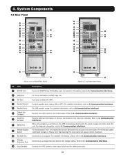
...INPUT DRY CONTACT REPO CHARGER DETECTION MANUAL BYPASS SWITCH WARNING: OPENING THIS COVER PLATE WILL CAUSE INVERTER SHUTDOWN.ONLY AUTHORIZED SERVICE PERSONNEL CAN OPEN AND OPERATE IT. For more information contact Tripp Lite. Receive the UPS system's ... I ON O OFF R S T N INPUT BREAKER R S T N BYPASS BREAKER +N - 240V DC 240V DC BATTERY INPUT R S T N AC INPUT R S T N UPS OUTPUT 9 10 11 19 18 17 20 20 21 (Figure 4-6: SUTX20K Rear Panel) 21 (Figure 4-7: SUTX40K Rear Panel) No. For detailed information, refer to 6. Controls parallel ports' ...
...INPUT DRY CONTACT REPO CHARGER DETECTION MANUAL BYPASS SWITCH WARNING: OPENING THIS COVER PLATE WILL CAUSE INVERTER SHUTDOWN.ONLY AUTHORIZED SERVICE PERSONNEL CAN OPEN AND OPERATE IT. For more information contact Tripp Lite. Receive the UPS system's ... I ON O OFF R S T N INPUT BREAKER R S T N BYPASS BREAKER +N - 240V DC 240V DC BATTERY INPUT R S T N AC INPUT R S T N UPS OUTPUT 9 10 11 19 18 17 20 20 21 (Figure 4-6: SUTX20K Rear Panel) 21 (Figure 4-7: SUTX40K Rear Panel) No. For detailed information, refer to 6. Controls parallel ports' ...
Owners Manual
Page 30
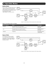
... OFF for 9.9 seconds) The alarm beeps once every 0.5 second. (ON for 0.1 second and OFF for 0.9 second) Long beep. 5. During bypass mode, the BYPASS LED indicator ( BYPASS ) illuminates (yellow). MAINS Rectifier Inverter LOAD Batteries (Figure 5-4: Path of Electrical Power through the UPS in Bypass Mode) 30 Operation Modes Battery Mode When the UPS is operating during a power outage, the batteries provide DC power, which maintains inverter operation...
... OFF for 9.9 seconds) The alarm beeps once every 0.5 second. (ON for 0.1 second and OFF for 0.9 second) Long beep. 5. During bypass mode, the BYPASS LED indicator ( BYPASS ) illuminates (yellow). MAINS Rectifier Inverter LOAD Batteries (Figure 5-4: Path of Electrical Power through the UPS in Bypass Mode) 30 Operation Modes Battery Mode When the UPS is operating during a power outage, the batteries provide DC power, which maintains inverter operation...

Owners Manual
Page 33
6. Use Tripp Lite's free PowerAlert® power management software (available for UPS parallel communication. Monitors the load level, battery status, battery voltage, UPS operation mode, input voltage, input frequency, output voltage and UPS temperature. 2. When four UPS systems are paralleled, turn off the middle UPS DIP switches and turn on each UPS DIP switches. 2. It also provides dry contact functions...
6. Use Tripp Lite's free PowerAlert® power management software (available for UPS parallel communication. Monitors the load level, battery status, battery voltage, UPS operation mode, input voltage, input frequency, output voltage and UPS temperature. 2. When four UPS systems are paralleled, turn off the middle UPS DIP switches and turn on each UPS DIP switches. 2. It also provides dry contact functions...

Owners Manual
Page 38
...(+)/ BUS(-) (Level 3) MAINTENANCE (Level 4) MODEL NAME SERIAL NUMBER FIRMWARE VERSION PFC/ INV & SYSTEM STATISTICS RUN TIME/ ON BAT COUNTS/ ON BYPASS COUNTS/ TOTAL OF EVENT LOG EVENT LOG EVENT LOG REAR TIME CLOCK DATE(Y-M-D)/ TIME(H-M-S) CONTROL & TEST BATT TEST/ BEEP ENABLE LANGUAGE SETUP LANGUAGE (Figure 8-1: LCD Display Hierarchy) Notes: 1. LCD Display and Settings is for information about...
...(+)/ BUS(-) (Level 3) MAINTENANCE (Level 4) MODEL NAME SERIAL NUMBER FIRMWARE VERSION PFC/ INV & SYSTEM STATISTICS RUN TIME/ ON BAT COUNTS/ ON BYPASS COUNTS/ TOTAL OF EVENT LOG EVENT LOG EVENT LOG REAR TIME CLOCK DATE(Y-M-D)/ TIME(H-M-S) CONTROL & TEST BATT TEST/ BEEP ENABLE LANGUAGE SETUP LANGUAGE (Figure 8-1: LCD Display Hierarchy) Notes: 1. LCD Display and Settings is for information about...
Owners Manual
Page 47
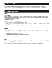
...error, overload, internal fault, etc. For optimum battery performance and life, operate at www.tripplite.com for all fans work in Normal [Online] Mode). When the UPS needs to avoid overheating. Maintenance UPS 1. UPS Regular Inspection: Regularly check the UPS every six months and inspect: 1) Whether the UPS, LEDs and alarm... a normal battery lifetime. 1. Please follow the suggestions below to penetrate vents and openings during cleaning. 2. If not, replace the fans. Note: Contact Tripp Lite Technical Support for an extended period of time, the batteries must be ...
...error, overload, internal fault, etc. For optimum battery performance and life, operate at www.tripplite.com for all fans work in Normal [Online] Mode). When the UPS needs to avoid overheating. Maintenance UPS 1. UPS Regular Inspection: Regularly check the UPS every six months and inspect: 1) Whether the UPS, LEDs and alarm... a normal battery lifetime. 1. Please follow the suggestions below to penetrate vents and openings during cleaning. 2. If not, replace the fans. Note: Contact Tripp Lite Technical Support for an extended period of time, the batteries must be ...
Owners Manual
Page 48
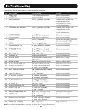
... eliminated but the alarm still appears, contact Tripp Lite Technical Support. 48 Input SCR driver is damaged. Auxiliary power is damaged. 2. Inverter's driver is damaged. 2. Output has abnormalities. 2. Rectifier tube is damaged. Inverter SCR is too high. Contact service personnel. 1. Decrease load on UPS. 3. Clean filters if installed. Contact service personnel. Check the batteries' polarity. Contact service personnel. Contact service personnel. Note: If...
... eliminated but the alarm still appears, contact Tripp Lite Technical Support. 48 Input SCR driver is damaged. Auxiliary power is damaged. 2. Inverter's driver is damaged. 2. Output has abnormalities. 2. Rectifier tube is damaged. Inverter SCR is too high. Contact service personnel. 1. Decrease load on UPS. 3. Clean filters if installed. Contact service personnel. Check the batteries' polarity. Contact service personnel. Contact service personnel. Note: If...

Owners Manual
Page 52
... have other rights which vary from Tripp Lite through authorized service partners (in its sole discretion. This Warranty gives you specific legal rights, and you . Chicago IL 60609; The series number can be confused with all applicable instructions, to use intended. THIS WARRANTY ... OTHER THAN THE WARRANTY EXPRESSLY SET FORTH HEREIN. USA WARNING: The individual user should not be found on the product nameplate label, along with the marketing name or model number of initial purchase. WEEE Compliance Information for Tripp Lite Customers and Recyclers (European Union...
... have other rights which vary from Tripp Lite through authorized service partners (in its sole discretion. This Warranty gives you specific legal rights, and you . Chicago IL 60609; The series number can be confused with all applicable instructions, to use intended. THIS WARRANTY ... OTHER THAN THE WARRANTY EXPRESSLY SET FORTH HEREIN. USA WARNING: The individual user should not be found on the product nameplate label, along with the marketing name or model number of initial purchase. WEEE Compliance Information for Tripp Lite Customers and Recyclers (European Union...

