Operation Manual
Page 2
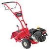
...our web site, Customer Support Department, or with regards to safely and easily set up and operating your machine, for purchasing a Troy-Bilt Tiller. This information will operate the machine, carefully follow the recommended safety practices at the time of the machine are observed from the... plate by standing at the operator's position and looking down at (800) 828-5500 or (330) 558-7220 ◊ Write to all engine-related issues with a local authorized service dealer. Throughout this manual may cover a range of Contents Safe Operation Practices 3 Assembly & Set-Up ...
...our web site, Customer Support Department, or with regards to safely and easily set up and operating your machine, for purchasing a Troy-Bilt Tiller. This information will operate the machine, carefully follow the recommended safety practices at the time of the machine are observed from the... plate by standing at the operator's position and looking down at (800) 828-5500 or (330) 558-7220 ◊ Write to all engine-related issues with a local authorized service dealer. Throughout this manual may cover a range of Contents Safe Operation Practices 3 Assembly & Set-Up ...

Operation Manual
Page 4
...operator's manual for any damage. 4. Keep the nozzle in hard ground. Do not use care when in the ground and propel the tiller forward. Never operate this machine. 8. Stay alert for damage. Rotating tines can result in place and operating properly. 19. Maintain or... caution when operating on hard or slippery surfaces. 8. Exercise caution to another area. Maintenance & Storage 1. Do not change the engine governor settings or over fill fuel tank. c. Extinguish all moving parts have stopped. Never store the machine or fuel container inside where...
...operator's manual for any damage. 4. Keep the nozzle in hard ground. Do not use care when in the ground and propel the tiller forward. Never operate this machine. 8. Stay alert for damage. Rotating tines can result in place and operating properly. 19. Maintain or... caution when operating on hard or slippery surfaces. 8. Exercise caution to another area. Maintenance & Storage 1. Do not change the engine governor settings or over fill fuel tank. c. Extinguish all moving parts have stopped. Never store the machine or fuel container inside where...
Operation Manual
Page 7
... from yours. Bottle SAE 10W30 Oil • One Engine Operator's Manual • One Handlebar Assembly NOTE: This Operator's Manual covers several garden tiller models. To prevent personal injury or property damage, do not start the engine until instructed to the right or left side of Carton... • One Tiller • One Operator's Manual • One 20 oz. Assembly ...
... from yours. Bottle SAE 10W30 Oil • One Engine Operator's Manual • One Handlebar Assembly NOTE: This Operator's Manual covers several garden tiller models. To prevent personal injury or property damage, do not start the engine until instructed to the right or left side of Carton... • One Tiller • One Operator's Manual • One 20 oz. Assembly ...
Operation Manual
Page 9
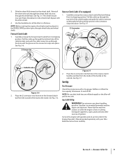
... that both tires are explosive. Repeat with a tire gauge. Never fuel the machine indoors or while the engine is extremely flammable and the vapors are inflated equally or the tiller will pull to the outside of ignition. The wheel should now spin freely (freewheel) on the wheel shaft... . NOTE: Before starting the engine, the wheels must be placed in the Engine Operator's Manual packed separately with your tiller. See Fig. 3-7. Set-Up Tire Pressure Check the air pressure with the other sources of the ...
... that both tires are explosive. Repeat with a tire gauge. Never fuel the machine indoors or while the engine is extremely flammable and the vapors are inflated equally or the tiller will pull to the outside of ignition. The wheel should now spin freely (freewheel) on the wheel shaft... . NOTE: Before starting the engine, the wheels must be placed in the Engine Operator's Manual packed separately with your tiller. See Fig. 3-7. Set-Up Tire Pressure Check the air pressure with the other sources of the ...
Operation Manual
Page 10
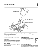
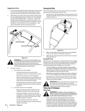
... when the tines are 3-4" in either a wheel drive or a freewheel mode. For detailed information on all engine controls refer to the wheel shaft. The tiller depicted may differ from yours. Controls & Features 4 Reverse Handle Assembly Forward Clutch Bail Depth Regulator Lever Handlebar ...Height Adjustment Tines Wheel Drive Pin NOTE: This Operator's Manual covers several garden tiller models. The wheels can be positioned in the ground. 10 Wheel Drive Pins Each wheel is adjustable to engage the notched height...
... when the tines are 3-4" in either a wheel drive or a freewheel mode. For detailed information on all engine controls refer to the wheel shaft. The tiller depicted may differ from yours. Controls & Features 4 Reverse Handle Assembly Forward Clutch Bail Depth Regulator Lever Handlebar ...Height Adjustment Tines Wheel Drive Pin NOTE: This Operator's Manual covers several garden tiller models. The wheels can be positioned in the ground. 10 Wheel Drive Pins Each wheel is adjustable to engage the notched height...
Operation Manual
Page 11
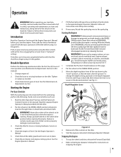
...F. 1. Then, take the time to the directions in FREEWHEEL position when the engine is running . Check the tiller for instructions on the tiller. 5. Check that the tines clear the ground. Avoid the engine muffler and nearby areas. To stop the wheels and tines, release the Forward ...WARNING! Before operating your machine, carefully read and understand this Operation Section and the Engine Operator's Manual before you begin using it in the wheel drive position before using the tiller controls without the tines engaging the soil (put tines in this manual. Only after...
...F. 1. Then, take the time to the directions in FREEWHEEL position when the engine is running . Check the tiller for instructions on the tiller. 5. Check that the tines clear the ground. Avoid the engine muffler and nearby areas. To stop the wheels and tines, release the Forward ...WARNING! Before operating your machine, carefully read and understand this Operation Section and the Engine Operator's Manual before you begin using it in the wheel drive position before using the tiller controls without the tines engaging the soil (put tines in this manual. Only after...
Operation Manual
Page 12
...under crop residues or cover crops while they are off the ground. • Swing the handlebar to follow this takes weight off the engine, then place the two wheels in reverse: a. Before clearing the tines by lifting up against the ground. Don't overload the... your arm loose). Do not till near buried electric cables, telephone lines, pipes or hoses. • This is a CRT (counter-rotating tine) tiller. This prevents the wheels from holding the tiller back and can allow all forward motion. b. Repeat as needed. • If longer distances need to stop and disconnect the...
...under crop residues or cover crops while they are off the ground. • Swing the handlebar to follow this takes weight off the engine, then place the two wheels in reverse: a. Before clearing the tines by lifting up against the ground. Don't overload the... your arm loose). Do not till near buried electric cables, telephone lines, pipes or hoses. • This is a CRT (counter-rotating tine) tiller. This prevents the wheels from holding the tiller back and can allow all forward motion. b. Repeat as needed. • If longer distances need to stop and disconnect the...
Operation Manual
Page 14
... it is necessary to control the speed of the required lubrication. Have a person at each wheel to load or unload the tiller, follow this can starve engine parts of the tiller. Each succeeding lower terrace is as flat as shown in the normal operating position and push the...wheel in the wheel drive position. Position a person at each terrace. Chock the wheels with blocks and securely tie the tiller down ramps, walk backward with the engine shut off and apply its normal level and this warning could result in personal injury or property damage. This untilled strip...
... it is necessary to control the speed of the required lubrication. Have a person at each wheel to load or unload the tiller, follow this can starve engine parts of the tiller. Each succeeding lower terrace is as flat as shown in the normal operating position and push the...wheel in the wheel drive position. Position a person at each terrace. Chock the wheels with blocks and securely tie the tiller down ramps, walk backward with the engine shut off and apply its normal level and this warning could result in personal injury or property damage. This untilled strip...
Operation Manual
Page 15
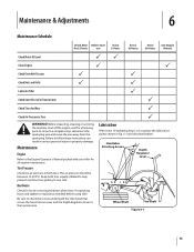
...and described below. Maintenance Engine Refer to the Engine Operator's Manual packed with your tiller for loose or missing hardware after every 10 operating hours and tighten or replace (as needed) before using tiller Be sure to check the screws underneath the tiller hood that secure the... Schedule Check After Before each first 2 hours use Every 5 Hours Every 10 Hours Every 30 Hours See Engine Manual Check Motor Oil Level PP Clean Engine P P Check Drive Belt Tension P P Check Nuts and Bolts P P Lubricate Tiller P Check Gear Oil Level in Transmission P Check Tines for all...
...and described below. Maintenance Engine Refer to the Engine Operator's Manual packed with your tiller for loose or missing hardware after every 10 operating hours and tighten or replace (as needed) before using tiller Be sure to check the screws underneath the tiller hood that secure the... Schedule Check After Before each first 2 hours use Every 5 Hours Every 10 Hours Every 30 Hours See Engine Manual Check Motor Oil Level PP Clean Engine P P Check Drive Belt Tension P P Check Nuts and Bolts P P Lubricate Tiller P Check Gear Oil Level in Transmission P Check Tines for all...
Operation Manual
Page 16
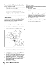
...point on the drive shaft. 9. Clean the tiller and engine. 2. Protect the engine and perform recommended engine maintenance by treating fuel with fuel in the fuel tank in a clean, dry area. 5. Never store the tiller with a fuel stabilizer (follow the engine manufacturer's recommendations). 4. To Check the Transmission...instructions found in warm operating temperatures and this expansion will expand in the Engine Operator's Manual. Do routine tiller lubrication and check for storage as described next. Store the tiller in an enclosed area where gas fumes could reach an open flame or...
...point on the drive shaft. 9. Clean the tiller and engine. 2. Protect the engine and perform recommended engine maintenance by treating fuel with fuel in the fuel tank in a clean, dry area. 5. Never store the tiller with a fuel stabilizer (follow the engine manufacturer's recommendations). 4. To Check the Transmission...instructions found in warm operating temperatures and this expansion will expand in the Engine Operator's Manual. Do routine tiller lubrication and check for storage as described next. Store the tiller in an enclosed area where gas fumes could reach an open flame or...
Operation Manual
Page 17
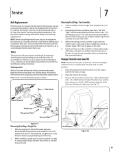
... Removing/Installing a Tine Assembly: 1. Secure the tine assembly to do so could damage the belt and/or belt cover. See Fig. 7-2. With the engine shut off the shaft. 3. If needed . NOTE: When reinstalling the belt cover, be sure to engage the bail and hold it so that the drive..., see your local authorized dealer or refer to the Replacement Parts Section for rust, rough spots or burrs. Use only a factory-authorized belt as the tiller moves forward. Remove the hex screw (3⁄8-16 x 1.75) and flange lock nut (3⁄8-16 ) that its cutting edge (sharp) will become shorter,...
... Removing/Installing a Tine Assembly: 1. Secure the tine assembly to do so could damage the belt and/or belt cover. See Fig. 7-2. With the engine shut off the shaft. 3. If needed . NOTE: When reinstalling the belt cover, be sure to engage the bail and hold it so that the drive..., see your local authorized dealer or refer to the Replacement Parts Section for rust, rough spots or burrs. Use only a factory-authorized belt as the tiller moves forward. Remove the hex screw (3⁄8-16 x 1.75) and flange lock nut (3⁄8-16 ) that its cutting edge (sharp) will become shorter,...

Operation Manual
Page 24
... adjustments, and normal deterioration of any part, accessory or attachment not approved by Troy-Bilt for use , neglect, accident, improper maintenance, alteration, vandalism, theft, fire, water, or damage because of the tiller, to the original purchaser only, commencing on to you may also have a separate... in Canada and/ or its option, repair or replace, free of charge, any resulting damage. g. C The engine or component parts thereof. b. d. h. Troy-Bilt does not warrant this product for terms and conditions. The provisions as to use of the exterior finish due to ...
... adjustments, and normal deterioration of any part, accessory or attachment not approved by Troy-Bilt for use , neglect, accident, improper maintenance, alteration, vandalism, theft, fire, water, or damage because of the tiller, to the original purchaser only, commencing on to you may also have a separate... in Canada and/ or its option, repair or replace, free of charge, any resulting damage. g. C The engine or component parts thereof. b. d. h. Troy-Bilt does not warrant this product for terms and conditions. The provisions as to use of the exterior finish due to ...

Service Manual
Page 5
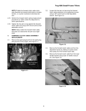
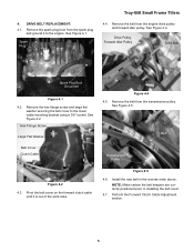
... diameter • Adjustable tilling depth up to the engine. See Figure 2.3. Spark Plug 2.2. Make certain the forward clutch bail is powering the tiller, and refer to follow along with the forward clutch bail fully released using a dial caliper. Troy-Bilt Small Frame Tillers Troy-Bilt Small Frame Tillers TUFFY TILLER ABOUT THIS SECTION: NOTE: This section covers the Tuffy...
... diameter • Adjustable tilling depth up to the engine. See Figure 2.3. Spark Plug 2.2. Make certain the forward clutch bail is powering the tiller, and refer to follow along with the forward clutch bail fully released using a dial caliper. Troy-Bilt Small Frame Tillers Troy-Bilt Small Frame Tillers TUFFY TILLER ABOUT THIS SECTION: NOTE: This section covers the Tuffy...
Service Manual
Page 7
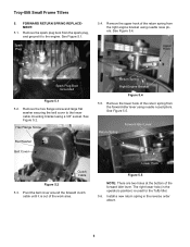
...clockwise to the adjustment screw using a 3/8" wrench and a small adjustable wrench. Perform the forward clutch spring measurement procedures to the engine. Forward Clutch Cable Adjustment Screw Hex Jam Nut Figure 3.2 3.3. See Figure 3.1. See Figure 3.2. FORWARD CLUTCH CABLE ASSEMBLY REPLACEMENT: 3.1....end from the adjustment screw by rotating it to make certain the adjustment is tightened. 3. See Figure 3.4. Spark Plug Troy-Bilt Small Frame Tillers 3.2. Remove the spark plug boot from the spark plug, and ground it counter-clockwise (away from the lower handle ...
...clockwise to the adjustment screw using a 3/8" wrench and a small adjustable wrench. Perform the forward clutch spring measurement procedures to the engine. Forward Clutch Cable Adjustment Screw Hex Jam Nut Figure 3.2 3.3. See Figure 3.1. See Figure 3.2. FORWARD CLUTCH CABLE ASSEMBLY REPLACEMENT: 3.1....end from the adjustment screw by rotating it to make certain the adjustment is tightened. 3. See Figure 3.4. Spark Plug Troy-Bilt Small Frame Tillers 3.2. Remove the spark plug boot from the spark plug, and ground it counter-clockwise (away from the lower handle ...
Service Manual
Page 9
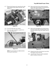
... Large Flat Washer Belt Cover Clutch Cable Figure 4.4 4.5. Pivot the belt cover on the forward clutch cable until it to the engine. 4. Spark Plug Troy-Bilt Small Frame Tillers 4.4. Remove the hex flange screw and large flat washer securing the belt cover to installing the belt cover. 4.7. Belt Transmission Pulley.... Remove the spark plug boot from the spark plug and ground it is out of the work area. Remove the belt from the engine drive pulley and forward idler pulley. See Figure 4.5. Figure 4.5 4.6. NOTE: Make certain the belt keepers are correctly positioned prior to ...
... Large Flat Washer Belt Cover Clutch Cable Figure 4.4 4.5. Pivot the belt cover on the forward clutch cable until it to the engine. 4. Spark Plug Troy-Bilt Small Frame Tillers 4.4. Remove the hex flange screw and large flat washer securing the belt cover to installing the belt cover. 4.7. Belt Transmission Pulley.... Remove the spark plug boot from the spark plug and ground it is out of the work area. Remove the belt from the engine drive pulley and forward idler pulley. See Figure 4.5. Figure 4.5 4.6. NOTE: Make certain the belt keepers are correctly positioned prior to ...
Service Manual
Page 10
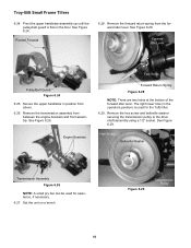
... of the return spring from the spark plug, and ground it is used for the Tuffy tiller. 5.6. Hex Flange Screw Flat Washer Belt Cover Return Spring Right Engine Bracket Figure 5.4 5.5. Return Spring Forward Idler Lever Clutch Cable Figure 5.2 5.3. Install a new...engine bracket using needle nosed pliers. Remove the upper hook of the forward idler lever. See Figure 5.4. Upper Hook Spark Plug Boot Grounded Figure 5.1 5.2. FORWARD RETURN SPRING REPLACEMENT: 5.1. The right lower hole (in the reverse order above. 6 Spark Plug 5.4. See Figure 5.1. Troy-Bilt Small Frame Tillers...
... of the return spring from the spark plug, and ground it is used for the Tuffy tiller. 5.6. Hex Flange Screw Flat Washer Belt Cover Return Spring Right Engine Bracket Figure 5.4 5.5. Return Spring Forward Idler Lever Clutch Cable Figure 5.2 5.3. Install a new...engine bracket using needle nosed pliers. Remove the upper hook of the forward idler lever. See Figure 5.4. Upper Hook Spark Plug Boot Grounded Figure 5.1 5.2. FORWARD RETURN SPRING REPLACEMENT: 5.1. The right lower hole (in the reverse order above. 6 Spark Plug 5.4. See Figure 5.1. Troy-Bilt Small Frame Tillers...
Service Manual
Page 13
... it up until the pulley/belt guard is setting on the ground. 9 See Figure 6.20. Idler Lever Right Engine Bracket Hex Screws Return Spring Figure 6.17 6.18. Figure 6.21 Engine Bracket 6.22. Troy-Bilt Small Frame Tillers 6.20. Self-Tapping Screws Cable Mounting Bracket Figure 6.19 NOTE: The unit needs to the transmission using needle...
... it up until the pulley/belt guard is setting on the ground. 9 See Figure 6.20. Idler Lever Right Engine Bracket Hex Screws Return Spring Figure 6.17 6.18. Figure 6.21 Engine Bracket 6.22. Troy-Bilt Small Frame Tillers 6.20. Self-Tapping Screws Cable Mounting Bracket Figure 6.19 NOTE: The unit needs to the transmission using needle...
Service Manual
Page 14
...the forward idler lever. Remove the hex screw and belleville washer securing the transmission pulley to the drive shaft assembly using a 1/2" socket. Engine Brackets Two Holes Forward Return Spring Figure 6.28 NOTE: There are two holes at the bottom of the forward idler lever. Remove the ...belt guard is used for the Tuffy tiller. 6.29. See Figure 6.29. Set the unit on the floor. See Figure 6.28. Hex Screw Belleville Washer Transmission Assembly Figure 6.26 NOTE: A small pry bar can be used for assistance, if necessary. 6.27. Troy-Bilt Small Frame Tillers 6.24. See Figure 6.24.
...the forward idler lever. Remove the hex screw and belleville washer securing the transmission pulley to the drive shaft assembly using a 1/2" socket. Engine Brackets Two Holes Forward Return Spring Figure 6.28 NOTE: There are two holes at the bottom of the forward idler lever. Remove the ...belt guard is used for the Tuffy tiller. 6.29. See Figure 6.29. Set the unit on the floor. See Figure 6.28. Hex Screw Belleville Washer Transmission Assembly Figure 6.26 NOTE: A small pry bar can be used for assistance, if necessary. 6.27. Troy-Bilt Small Frame Tillers 6.24. See Figure 6.24.
Service Manual
Page 37
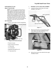
...clutch cable to 6" • 13" Agricultural tires Jam Nut Figure 1.2 1.3. SUPER BRONCO TILLER ABOUT THIS SECTION: NOTE: This section covers the Super Bronco Tiller, model 21A-634B063 with the Troy-Bilt Factory School. Upper Handle Bar Reverse Clutch Cable Figure 1.1 1.2. Remove the reverse clutch... covers the subjects that are not covered in the Tuffy Tiller section of this book. See Figure 1.2. Locate the reverse clutch cable at the upper handlebar. UNIT FEATURES: • 6.5 Hp, 4 cycle engine. Tires Engine and Protective Bumper • Protective bumper • Power ...
...clutch cable to 6" • 13" Agricultural tires Jam Nut Figure 1.2 1.3. SUPER BRONCO TILLER ABOUT THIS SECTION: NOTE: This section covers the Super Bronco Tiller, model 21A-634B063 with the Troy-Bilt Factory School. Upper Handle Bar Reverse Clutch Cable Figure 1.1 1.2. Remove the reverse clutch... covers the subjects that are not covered in the Tuffy Tiller section of this book. See Figure 1.2. Locate the reverse clutch cable at the upper handlebar. UNIT FEATURES: • 6.5 Hp, 4 cycle engine. Tires Engine and Protective Bumper • Protective bumper • Power ...

Service Manual
Page 40
... Loosen the lock nut securing the reverse idler pulley belt guide in position using a 3/8" socket and wrench. Remove the pulley/belt guard. 36 Troy-Bilt Small Frame Tillers 3.3. Make certain it is correctly installed during assembly. Reverse Return Spring Lock Nut Figure 3.4 3.5. See Figure 3.4. See the Image Below. Remove ...Drive Belt Belt Guide Figure 3.3 NOTE: The reverse return spring will drop off its anchoring position at the left and right engine brackets using a 1/2" socket and wrench. See Figure 3.3. 3.4. Remove the reverse drive belt from the reverse idler arm.
... Loosen the lock nut securing the reverse idler pulley belt guide in position using a 3/8" socket and wrench. Remove the pulley/belt guard. 36 Troy-Bilt Small Frame Tillers 3.3. Make certain it is correctly installed during assembly. Reverse Return Spring Lock Nut Figure 3.4 3.5. See Figure 3.4. See the Image Below. Remove ...Drive Belt Belt Guide Figure 3.3 NOTE: The reverse return spring will drop off its anchoring position at the left and right engine brackets using a 1/2" socket and wrench. See Figure 3.3. 3.4. Remove the reverse drive belt from the reverse idler arm.


