Operation Manual
Page 2
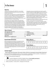
...questions regarding the controls, operation, or maintenance of the tine shield. Please be found at the front right corner of this page. If you , and any problems or questions concerning the machine, phone a authorized Troy-Bilt service dealer or contact us on this Operator's Manual... this manual frequently to familiarize yourself with your complete satisfaction at (800) 828-5500 or (330) 558-7220 ◊ Write to Troy-Bilt LLC • P.O. Please refer to the engine manufacturer's Owner's/Operator's Manual, packed separately with the machine, its features and operation....
...questions regarding the controls, operation, or maintenance of the tine shield. Please be found at the front right corner of this page. If you , and any problems or questions concerning the machine, phone a authorized Troy-Bilt service dealer or contact us on this Operator's Manual... this manual frequently to familiarize yourself with your complete satisfaction at (800) 828-5500 or (330) 558-7220 ◊ Write to Troy-Bilt LLC • P.O. Please refer to the engine manufacturer's Owner's/Operator's Manual, packed separately with the machine, its features and operation....

Operation Manual
Page 4
... sources of ignition. l. Exercise caution to another area. Thoroughly inspect the machine for hidden hazards or traffic. Disengage all times until the tines come to do not restrain the machine. 6. Do not touch. 15. Allow a machine to cool at high transport speeds on or ...1. Never operate the machine at least two minutes before storing. After striking a foreign object, stop the engine and make certain the tines and all shields, guards, and safety devices in contact with safety devices. Always refer to allow space for important details if the machine...
... sources of ignition. l. Exercise caution to another area. Thoroughly inspect the machine for hidden hazards or traffic. Disengage all times until the tines come to do not restrain the machine. 6. Do not touch. 15. Allow a machine to cool at high transport speeds on or ...1. Never operate the machine at least two minutes before storing. After striking a foreign object, stop the engine and make certain the tines and all shields, guards, and safety devices in contact with safety devices. Always refer to allow space for important details if the machine...
Operation Manual
Page 6
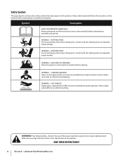
Symbol Description READ THE OPERATOR'S MANUAL(S) Read, understand, and follow all instructions in a poorly ventilated area. ROTATING TINES Do not put hands or feet near rotating parts. Allow engine and muffler to cool before refueling. WARNING! Contact with the rotating ...IS FLAMMABLE Allow the engine to persons who read, understand and follow the warnings and instructions in this manual and on this product. ROTATING TINES Do not put hands or feet near rotating parts. Engine exhaust contains carbon monoxide, an odorless and deadly gas. CARBON MONOXIDE Never run an...
Symbol Description READ THE OPERATOR'S MANUAL(S) Read, understand, and follow all instructions in a poorly ventilated area. ROTATING TINES Do not put hands or feet near rotating parts. Allow engine and muffler to cool before refueling. WARNING! Contact with the rotating ...IS FLAMMABLE Allow the engine to persons who read, understand and follow the warnings and instructions in this manual and on this product. ROTATING TINES Do not put hands or feet near rotating parts. Engine exhaust contains carbon monoxide, an odorless and deadly gas. CARBON MONOXIDE Never run an...
Operation Manual
Page 8
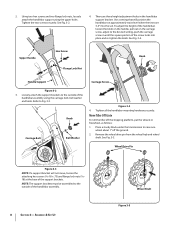
... that will not move, loosen the attaching hex screws (5⁄16-18 x .75) and flange lock nuts (5⁄1618) at approximately waist level when the tines are three height adjustment holes in until the square portion of the support brackets. Loosely attach the support brackets to raise one wheel about 1" off...
... that will not move, loosen the attaching hex screws (5⁄16-18 x .75) and flange lock nuts (5⁄1618) at approximately waist level when the tines are three height adjustment holes in until the square portion of the support brackets. Loosely attach the support brackets to raise one wheel about 1" off...
Operation Manual
Page 10
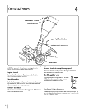
... click pin that secures the wheel to engage the notched height settings. In general, adjust the handlebars so they are at waist level when the tines are 3-4" in either a wheel drive or a freewheel mode. The wheels can be positioned in the ground. 10 Wheel Drive Pins Each wheel is adjustable... back and slide it up or down to the wheel shaft. Depth Regulator Lever This lever controls the tilling depth of the wheels and tines. Engine Controls Figure 4-1 Reverse Handle Assembly (if so equipped) The reverse handle assembly controls the engagement of the reverse drive of the wheels ...
... click pin that secures the wheel to engage the notched height settings. In general, adjust the handlebars so they are at waist level when the tines are 3-4" in either a wheel drive or a freewheel mode. The wheels can be positioned in the ground. 10 Wheel Drive Pins Each wheel is adjustable... back and slide it up or down to the wheel shaft. Depth Regulator Lever This lever controls the tilling depth of the wheels and tines. Engine Controls Figure 4-1 Reverse Handle Assembly (if so equipped) The reverse handle assembly controls the engagement of the reverse drive of the wheels ...
Operation Manual
Page 11
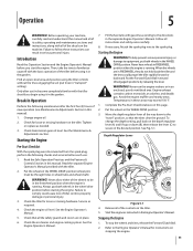
... Put the wheels in an enclosed, poorly ventilated area. See Fig, 5-1. Depth Regulator Lever B A Figure 5-1 4. To stop the wheels and tines, release the Forward Clutch Bail. 2. Put the wheels in the WHEEL DRIVE position (wheel pins must be in FREEWHEEL position when the engine is ... exhaust contains carbon monoxide, an odorless and deadly gas. Complete the Pre-Start Checklist above on the tiller. 5. Failure to equipment, put tines in this page. 2. Put the Forward Clutch Bail in the Engine Operator's Manual. Read the Safe Operation Practices and the Features & Controls...
... Put the wheels in an enclosed, poorly ventilated area. See Fig, 5-1. Depth Regulator Lever B A Figure 5-1 4. To stop the wheels and tines, release the Forward Clutch Bail. 2. Put the wheels in the WHEEL DRIVE position (wheel pins must be in FREEWHEEL position when the engine is ... exhaust contains carbon monoxide, an odorless and deadly gas. Complete the Pre-Start Checklist above on the tiller. 5. Failure to equipment, put tines in this page. 2. Put the Forward Clutch Bail in the Engine Operator's Manual. Read the Safe Operation Practices and the Features & Controls...
Operation Manual
Page 12
...! Before tilling, contact your telephone or utilities company and inquire if underground equipment or lines are used on the handlebars to try to the tines pull the Forward Clutch Bail up against the ground. Lift the handlebar with reverse handle: • Look behind and a little to follow ...to stop and disconnect the spark plug wire. Do not till near buried electric cables, telephone lines, pipes or hoses. • This is a CRT (counter-rotating tine) tiller. Release the bail to the right so the left so the right wheel takes a "step" backward. Let the tiller move in reverse...
...! Before tilling, contact your telephone or utilities company and inquire if underground equipment or lines are used on the handlebars to try to the tines pull the Forward Clutch Bail up against the ground. Lift the handlebar with reverse handle: • Look behind and a little to follow ...to stop and disconnect the spark plug wire. Do not till near buried electric cables, telephone lines, pipes or hoses. • This is a CRT (counter-rotating tine) tiller. Release the bail to the right so the left so the right wheel takes a "step" backward. Let the tiller move in reverse...
Operation Manual
Page 13
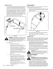
... the plants whose roots often grow close to dig deeper. If needed, lift up surface soil around plants to destroy weeds, see Fig. 5-4), Adjust the tines to dig only 1" to 2" deep. Operation 13 Figure 5-4 Suggested Tilling Patterns 1 2 • When preparing a seedbed, go over the same path ...the soil.) attempt to propel the tiller backward, towards the operator. • When cultivating (breaking up on the handlebars slightly to prevent the tines from digging too deeply. (Cultivating on a regular basis not only eliminates weeds, it may take three or four Without the wheels to hold...
... the plants whose roots often grow close to dig deeper. If needed, lift up surface soil around plants to destroy weeds, see Fig. 5-4), Adjust the tines to dig only 1" to 2" deep. Operation 13 Figure 5-4 Suggested Tilling Patterns 1 2 • When preparing a seedbed, go over the same path ...the soil.) attempt to propel the tiller backward, towards the operator. • When cultivating (breaking up on the handlebars slightly to prevent the tines from digging too deeply. (Cultivating on a regular basis not only eliminates weeds, it may take three or four Without the wheels to hold...
Operation Manual
Page 15
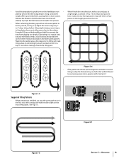
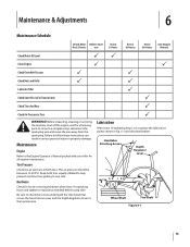
Tire Pressure Check the air pressure in serious personal injury or property damage. Handlebar Attaching Screws Depth Regulator Lever Wheel Shaft Tine Shaft Figure 6-1 15 Keep both tires. Hardware Check for all moving parts to come to a complete stop, disconnect the ...PP Clean Engine P P Check Drive Belt Tension P P Check Nuts and Bolts P P Lubricate Tiller P Check Gear Oil Level in Transmission P Check Tines for Wear P Check Air Pressure in Fig. 6-1 and described below. Maintenance Engine Refer to the Engine Operator's Manual packed with your tiller for loose ...
Tire Pressure Check the air pressure in serious personal injury or property damage. Handlebar Attaching Screws Depth Regulator Lever Wheel Shaft Tine Shaft Figure 6-1 15 Keep both tires. Hardware Check for all moving parts to come to a complete stop, disconnect the ...PP Clean Engine P P Check Drive Belt Tension P P Check Nuts and Bolts P P Lubricate Tiller P Check Gear Oil Level in Transmission P Check Tines for Wear P Check Air Pressure in Fig. 6-1 and described below. Maintenance Engine Refer to the Engine Operator's Manual packed with your tiller for loose ...
Operation Manual
Page 16
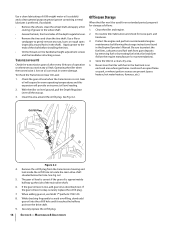
Transmission Gear Oil Check the transmission gear oil after every 30 hours of the depth regulator lever. • Remove the tines and clean the tine shaft. Store the tiller in warm operating temperatures and this expansion will expand in a clean, dry area. 5. Remove the oil fill plug ..., etc.). With the tiller on level ground, pull the Depth Regulator Lever all the way up the side of the shaft before installing the tines. • Oil the threads on the handlebar height adjustment screws and the handlebar attaching screws. Apply grease to gently remove any oil leak. ...
Transmission Gear Oil Check the transmission gear oil after every 30 hours of the depth regulator lever. • Remove the tines and clean the tine shaft. Store the tiller in warm operating temperatures and this expansion will expand in a clean, dry area. 5. Remove the oil fill plug ..., etc.). With the tiller on level ground, pull the Depth Regulator Lever all the way up the side of the shaft before installing the tines. • Oil the threads on the handlebar height adjustment screws and the handlebar attaching screws. Apply grease to gently remove any oil leak. ...
Operation Manual
Page 17
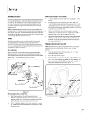
...4. See the Replacement Parts Section for rust, rough spots or burrs. If necessary, use and should be inspected at the beginning of eight tines mounted on the nuts. 2. Change Transmission Gear Oil NOTE: The transmission gear oil does not need to be changed unless it has been ... 2. Drain the oil from the fuel tank or run the engine until the fuel tank is tight before removal. When installing a single tine, be sure to the tine shaft. the-counter" belt may not perform satisfactorily. Remove the hex screw (3⁄8-16 x 1.75) and flange lock nut (3⁄8-16...
...4. See the Replacement Parts Section for rust, rough spots or burrs. If necessary, use and should be inspected at the beginning of eight tines mounted on the nuts. 2. Change Transmission Gear Oil NOTE: The transmission gear oil does not need to be changed unless it has been ... 2. Drain the oil from the fuel tank or run the engine until the fuel tank is tight before removal. When installing a single tine, be sure to the tine shaft. the-counter" belt may not perform satisfactorily. Remove the hex screw (3⁄8-16 x 1.75) and flange lock nut (3⁄8-16...
Operation Manual
Page 19
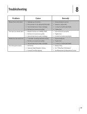
... loose in transmission pulley. 1. Contact local authorized dealer. 4. Internal transmission wear or damage. 1. Tine holder mounting hardware missing. 2. Review Operation section. 2. Replace Tines. 2. Contact local authorized dealer. 1. Worn, broken, or mis-adjusted drive belt(s). 3. Forward ...Improper Depth Regulator setting. 3. Replace or adjust belts. 3. Internal transmission wear or damage. 4. Tighten bolt. 3. Worn tines. 2. Contact local authorized dealer. 1. Inserts Drive Pins properly. 2. Wheel Drive Pins not in transmission pulley. 3. Internal...
... loose in transmission pulley. 1. Contact local authorized dealer. 4. Internal transmission wear or damage. 1. Tine holder mounting hardware missing. 2. Review Operation section. 2. Replace Tines. 2. Contact local authorized dealer. 1. Worn, broken, or mis-adjusted drive belt(s). 3. Forward ...Improper Depth Regulator setting. 3. Replace or adjust belts. 3. Internal transmission wear or damage. 4. Tighten bolt. 3. Worn tines. 2. Contact local authorized dealer. 1. Inserts Drive Pins properly. 2. Wheel Drive Pins not in transmission pulley. 3. Internal...
Operation Manual
Page 20
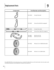
Parts Manual downloads are also available free of charge at www.troybilt.com. 20 Replacement Parts Component 9 Part Number and Description 954-04090 Forward Drive Belt 954-04091 Reverse Drive Belt (If so equipped) 946-04413 946-04414 Forward Drive Cable Reverse Drive Cable (If so equipped) 742-04227 742-04226 Bolo Tine, 10" (LT) Bolo Tine, 10" (RT) 934-04232 Wheels, 13 x5 x 6 (65M & 655 model) 934-04453 Wheels, 11 x 4-4 (64M model) Phone (800) 828-5500 to order replacement parts or a complete Parts Manual (have your full model number and serial number ready).
Parts Manual downloads are also available free of charge at www.troybilt.com. 20 Replacement Parts Component 9 Part Number and Description 954-04090 Forward Drive Belt 954-04091 Reverse Drive Belt (If so equipped) 946-04413 946-04414 Forward Drive Cable Reverse Drive Cable (If so equipped) 742-04227 742-04226 Bolo Tine, 10" (LT) Bolo Tine, 10" (RT) 934-04232 Wheels, 13 x5 x 6 (65M & 655 model) 934-04453 Wheels, 11 x 4-4 (64M model) Phone (800) 828-5500 to order replacement parts or a complete Parts Manual (have your full model number and serial number ready).

Service Manual
Page 5
... 2.3 2.4. See Figure 2.2. ENGINE: 1.1. ward clutch spring with Serial Number 1B212G80447. FORWARD CLUTCH CABLE ADJUSTMENT: 2.1. Spark Plug 2.2. Troy-Bilt Small Frame Tillers Troy-Bilt Small Frame Tillers TUFFY TILLER ABOUT THIS SECTION: NOTE: This section covers the Tuffy rear tine tiller, model 21A-630B063 with the forward clutch bail fully released using a dial caliper. UNIT FEATURES...
... 2.3 2.4. See Figure 2.2. ENGINE: 1.1. ward clutch spring with Serial Number 1B212G80447. FORWARD CLUTCH CABLE ADJUSTMENT: 2.1. Spark Plug 2.2. Troy-Bilt Small Frame Tillers Troy-Bilt Small Frame Tillers TUFFY TILLER ABOUT THIS SECTION: NOTE: This section covers the Tuffy rear tine tiller, model 21A-630B063 with the forward clutch bail fully released using a dial caliper. UNIT FEATURES...

Service Manual
Page 11
... hex flange screws securing the hood brackets to the right and left hood brackets using a 1/2" socket. Remove both self tapping hex flange screws securing the tine hood to the transmission assembly using a 3/8" socket. Hex Flange Screws Self Tapping Hex Flange Screws Figure 6.6 Hood Brackets Figure 6.11 7 Secure the handlebar from the... it 's nose. See Figure 6.11. Grasp the upper handlebar and pivot the unit NOTE: Perform the Drive Belt Replacement sec- See Figure 6.6. performing this section. Troy-Bilt Small Frame Tillers 6.
... hex flange screws securing the hood brackets to the right and left hood brackets using a 1/2" socket. Remove both self tapping hex flange screws securing the tine hood to the transmission assembly using a 3/8" socket. Hex Flange Screws Self Tapping Hex Flange Screws Figure 6.6 Hood Brackets Figure 6.11 7 Secure the handlebar from the... it 's nose. See Figure 6.11. Grasp the upper handlebar and pivot the unit NOTE: Perform the Drive Belt Replacement sec- See Figure 6.6. performing this section. Troy-Bilt Small Frame Tillers 6.

Service Manual
Page 12
Troy-Bilt Small Frame Tillers 6.12. Remove the depth regulator assembly and drag bar assembly. Cut A Way Wheels off the ground. Remove...6.15. Hood Brackets Drag Bar Figure 6.12 NOTE: There is resting on the tines and not on the trailing shield. See Image Below. See Figure 6.15. Lower the unit back onto the tines. See Figure 6.12. Remove both hair pins and clevis pins securing the wheel... Assembly 6.14. Cut A Way for Spiral Pin 6.13. NOTE: Make certain the unit is a cut a way in the tine hood to allow the depth bar's spiral pin to pass through. See Figure 6.14.
Troy-Bilt Small Frame Tillers 6.12. Remove the depth regulator assembly and drag bar assembly. Cut A Way Wheels off the ground. Remove...6.15. Hood Brackets Drag Bar Figure 6.12 NOTE: There is resting on the tines and not on the trailing shield. See Image Below. See Figure 6.15. Lower the unit back onto the tines. See Figure 6.12. Remove both hair pins and clevis pins securing the wheel... Assembly 6.14. Cut A Way for Spiral Pin 6.13. NOTE: Make certain the unit is a cut a way in the tine hood to allow the depth bar's spiral pin to pass through. See Figure 6.14.

Service Manual
Page 15
... washer from the drive shaft assembly. Transmission Pulley Key Belleville Troy-Bilt Small Frame Tillers 6.33. Raise the rear of the tine assemblies for correct installation. Forward Lever 2" x 4" Figure 6.33 6.34. Remove the hex screws and lock nuts securing the right and left tine assemblies using a 1/2" socket. Remove the hex screw securing the forward... Front Support Washer Hex Screw Figure 6.30 6.31. See Figure 6.31. Rotate the transmission horizontally 180°. Hex Screws and Lock Nuts Left and Right Tine Assemblies 11
... washer from the drive shaft assembly. Transmission Pulley Key Belleville Troy-Bilt Small Frame Tillers 6.33. Raise the rear of the tine assemblies for correct installation. Forward Lever 2" x 4" Figure 6.33 6.34. Remove the hex screws and lock nuts securing the right and left tine assemblies using a 1/2" socket. Remove the hex screw securing the forward... Front Support Washer Hex Screw Figure 6.30 6.31. See Figure 6.31. Rotate the transmission horizontally 180°. Hex Screws and Lock Nuts Left and Right Tine Assemblies 11
Service Manual
Page 16
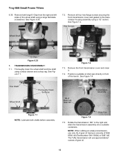
.... 7.2. Hex Screws Wheel Shaft Front Transmission Cover E-Clips Figure 6.35 7. NOTE: When refilling an empty transmission, use approximately? Troy-Bilt Small Frame Tillers 6.35. TRANSMISSION DISASSEMBLY: 7.1. See Figure 7.4. Remove the front transmission cover and clean it. 7.4. Rotate the... transmission will use only GL-4 gear oil having a viscosity of gear oil. 12 See Figure 7.2. Remove both shafts before assembly. Tine Shaft Wheel Shaft Thoroughly Clean Surfaces GL-4 85W-140 Gear Oil Transmission Assembly Figure 7.1 NOTE: Lubricate both large E-Clips from the ...
.... 7.2. Hex Screws Wheel Shaft Front Transmission Cover E-Clips Figure 6.35 7. NOTE: When refilling an empty transmission, use approximately? Troy-Bilt Small Frame Tillers 6.35. TRANSMISSION DISASSEMBLY: 7.1. See Figure 7.4. Remove the front transmission cover and clean it. 7.4. Rotate the... transmission will use only GL-4 gear oil having a viscosity of gear oil. 12 See Figure 7.2. Remove both shafts before assembly. Tine Shaft Wheel Shaft Thoroughly Clean Surfaces GL-4 85W-140 Gear Oil Transmission Assembly Figure 7.1 NOTE: Lubricate both large E-Clips from the ...
Service Manual
Page 17
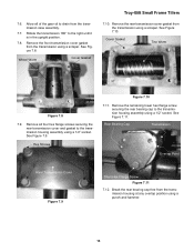
... at any overlap position using a scraper. See Figure 7.9. Remove all of the gear oil to the transmission housing assembly using a 1/2" socket. Wheel Worm Cover Gasket Troy-Bilt Small Frame Tillers 7.10. Rear Bearing Cap Transmission Overlap Point Rear Transmission Cover Figure 7.9 Short Hex Flange Screw Figure 7.11 7.12. See Figure 7.10. Hex... bearing cap to the right until it is in the upright position. 7.8. Remove the front transmission cover gasket from the transmission case assembly. 7.7. 7.6. Cover Gasket Tine Worm Figure 7.8 7.9. See Figure 7.11.
... at any overlap position using a scraper. See Figure 7.9. Remove all of the gear oil to the transmission housing assembly using a 1/2" socket. Wheel Worm Cover Gasket Troy-Bilt Small Frame Tillers 7.10. Rear Bearing Cap Transmission Overlap Point Rear Transmission Cover Figure 7.9 Short Hex Flange Screw Figure 7.11 7.12. See Figure 7.10. Hex... bearing cap to the right until it is in the upright position. 7.8. Remove the front transmission cover gasket from the transmission case assembly. 7.7. 7.6. Cover Gasket Tine Worm Figure 7.8 7.9. See Figure 7.11.
Service Manual
Page 23
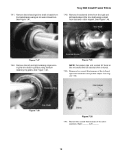
... with a small 90° bend at the end works well for external shim removal. 7.50. See Figure 7.47. Oil Seal Troy-Bilt Small Frame Tillers 7.49. See Figure 7.48. Measure the overall thicknesses of the left and right retaining rings securing the tine shaft in position using a small hook tool and a stick magnet.
... with a small 90° bend at the end works well for external shim removal. 7.50. See Figure 7.47. Oil Seal Troy-Bilt Small Frame Tillers 7.49. See Figure 7.48. Measure the overall thicknesses of the left and right retaining rings securing the tine shaft in position using a small hook tool and a stick magnet.


