Operation Manual
Page 2
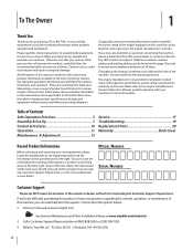
... can be aware that you seek technical support via our web site, Customer Support Department, or with your machine, for purchasing a Troy-Bilt Tiller. Please refer to the engine manufacturer's Owner's/Operator's Manual, packed separately with a local authorized service dealer. If you have ...service. It instructs you for more information. If applicable, the power testing information used to establish the power rating of the tine shield. This information will operate the machine, carefully follow the recommended safety practices at www.opei.org or the engine manufacturer's ...
... can be aware that you seek technical support via our web site, Customer Support Department, or with your machine, for purchasing a Troy-Bilt Tiller. Please refer to the engine manufacturer's Owner's/Operator's Manual, packed separately with a local authorized service dealer. If you have ...service. It instructs you for more information. If applicable, the power testing information used to establish the power rating of the tine shield. This information will operate the machine, carefully follow the recommended safety practices at www.opei.org or the engine manufacturer's ...

Operation Manual
Page 4
...Important Safe Operation Practices d. h. Wait 5 minutes before starting and operating. 12. Stop the machine if anyone enters the area. 5. The tines may catch in hard ground. Look down and behind the handles). Thoroughly inspect the machine for an extended period. 4 Section 2 - Use...or in this is complete. Muffler and engine become hot and can result in safe working condition. Do not touch. 15. Rotating tines can amputate hands and feet. 2. If the machine should start making any damage. 4. Inspect thoroughly for hidden hazards or traffic. Maintenance...
...Important Safe Operation Practices d. h. Wait 5 minutes before starting and operating. 12. Stop the machine if anyone enters the area. 5. The tines may catch in hard ground. Look down and behind the handles). Thoroughly inspect the machine for an extended period. 4 Section 2 - Use...or in this is complete. Muffler and engine become hot and can result in safe working condition. Do not touch. 15. Rotating tines can amputate hands and feet. 2. If the machine should start making any damage. 4. Inspect thoroughly for hidden hazards or traffic. Maintenance...
Operation Manual
Page 6
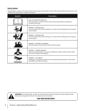
... or in this product. SAVE THESE INSTRUCTIONS! 6 Section 2 - Symbol Description READ THE OPERATOR'S MANUAL(S) Read, understand, and follow all instructions on the machine. WARNING- ROTATING TINES Do not put hands or feet near rotating parts. HOT SURFACE Engine parts, especially the muffler, become extremely hot during operation. WARNING! Allow engine and...
... or in this product. SAVE THESE INSTRUCTIONS! 6 Section 2 - Symbol Description READ THE OPERATOR'S MANUAL(S) Read, understand, and follow all instructions on the machine. WARNING- ROTATING TINES Do not put hands or feet near rotating parts. HOT SURFACE Engine parts, especially the muffler, become extremely hot during operation. WARNING! Allow engine and...
Operation Manual
Page 8
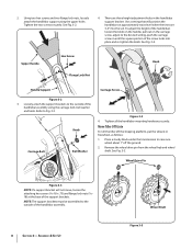
... that will not move, loosen the attaching hex screws (5⁄16-18 x .75) and flange lock nuts (5⁄1618) at approximately waist level when the tines are three height adjustment holes in until the square portion of the handlebars loosen the knob on the handle, pull out on the carriage screw...
... that will not move, loosen the attaching hex screws (5⁄16-18 x .75) and flange lock nuts (5⁄1618) at approximately waist level when the tines are three height adjustment holes in until the square portion of the handlebars loosen the knob on the handle, pull out on the carriage screw...
Operation Manual
Page 10
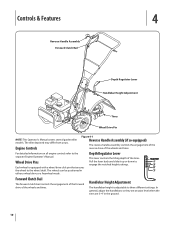
.... The wheels can be positioned in the ground. 10 Depth Regulator Lever This lever controls the tilling depth of the wheels and tines. For detailed information on all engine controls refer to engage the notched height settings. Controls & Features 4 Reverse Handle Assembly Forward ...Clutch Bail Depth Regulator Lever Handlebar Height Adjustment Tines Wheel Drive Pin NOTE: This Operator's Manual covers several garden tiller models. Pull the lever back and slide it up or down...
.... The wheels can be positioned in the ground. 10 Depth Regulator Lever This lever controls the tilling depth of the wheels and tines. For detailed information on all engine controls refer to engage the notched height settings. Controls & Features 4 Reverse Handle Assembly Forward ...Clutch Bail Depth Regulator Lever Handlebar Height Adjustment Tines Wheel Drive Pin NOTE: This Operator's Manual covers several garden tiller models. Pull the lever back and slide it up or down...
Operation Manual
Page 11
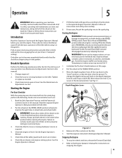
... oil. 2. Read the separate Engine Operator's Manual provided with gasoline according to the directions in the Engine Operator's Manual. Check that the tines clear the ground. See the Engine Operator's Manual. 7. If necessary, Attach the spark plug wire to the "travel" position, so that...change the depth setting, pull back on the tiller. Depth Regulator Lever B A Figure 5-1 4. Check for loose or missing hardware. Always put tines in an enclosed, poorly ventilated area. Check the tiller for loose or missing hardware on the depth regulator lever (A) and lift up or down...
... oil. 2. Read the separate Engine Operator's Manual provided with gasoline according to the directions in the Engine Operator's Manual. Check that the tines clear the ground. See the Engine Operator's Manual. 7. If necessary, Attach the spark plug wire to the "travel" position, so that...change the depth setting, pull back on the tiller. Depth Regulator Lever B A Figure 5-1 4. Check for loose or missing hardware. Always put tines in an enclosed, poorly ventilated area. Check the tiller for loose or missing hardware on the depth regulator lever (A) and lift up or down...
Operation Manual
Page 12
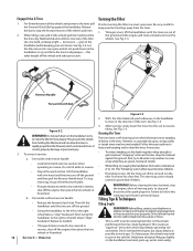
...This creates an "uppercut" tine action which could result in the tines. Do not till while in reverse for a few feet. See Fig. 5-3. 3. Do not till near buried electric cables, telephone lines, pipes or hoses. • This is a CRT (counter-rotating tine) tiller. Turning the ...Tiller Practice turning the tiller in freewheel. b. Then lift the handlebar until the tines are off the ground. • Swing the handlebar to rapidly propel the tiller forward...
...This creates an "uppercut" tine action which could result in the tines. Do not till while in reverse for a few feet. See Fig. 5-3. 3. Do not till near buried electric cables, telephone lines, pipes or hoses. • This is a CRT (counter-rotating tine) tiller. Turning the ...Tiller Practice turning the tiller in freewheel. b. Then lift the handlebar until the tines are off the ground. • Swing the handlebar to rapidly propel the tiller forward...
Operation Manual
Page 13
... the soil.) attempt to propel the tiller backward, towards the operator. • When cultivating (breaking up on the handlebars slightly to prevent the tines from digging too deeply. (Cultivating on a regular basis not only eliminates weeds, it may take three or four Without the wheels to hold the... tiller back, the tines will letting the newly worked soil set for better moisture absorption and faster plant growth.) Watering the garden area a few days prior to tilling ...
... the soil.) attempt to propel the tiller backward, towards the operator. • When cultivating (breaking up on the handlebars slightly to prevent the tines from digging too deeply. (Cultivating on a regular basis not only eliminates weeds, it may take three or four Without the wheels to hold the... tiller back, the tines will letting the newly worked soil set for better moisture absorption and faster plant growth.) Watering the garden area a few days prior to tilling ...
Operation Manual
Page 15
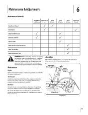
...Clean Engine P P Check Drive Belt Tension P P Check Nuts and Bolts P P Lubricate Tiller P Check Gear Oil Level in Transmission P Check Tines for Wear P Check Air Pressure in both tires equally inflated to help prevent machine from pulling to a complete stop, disconnect the spark plug wire... and move the wire away from the spark plug. Handlebar Attaching Screws Depth Regulator Lever Wheel Shaft Tine Shaft Figure 6-1 15 Failure to follow these instructions can result in Fig. 6-1 and described below. Hardware Check for loose or ...
...Clean Engine P P Check Drive Belt Tension P P Check Nuts and Bolts P P Lubricate Tiller P Check Gear Oil Level in Transmission P Check Tines for Wear P Check Air Pressure in both tires equally inflated to help prevent machine from pulling to a complete stop, disconnect the spark plug wire... and move the wire away from the spark plug. Handlebar Attaching Screws Depth Regulator Lever Wheel Shaft Tine Shaft Figure 6-1 15 Failure to follow these instructions can result in Fig. 6-1 and described below. Hardware Check for loose or ...
Operation Manual
Page 16
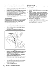
... sandpaper to gently remove any oil leak. Transmission Gear Oil Check the transmission gear oil after every 30 hours of the shaft before installing the tines. • Oil the threads on the drive shaft. 9. If the gear oil level is cool. While checking frequently to the ends of operation or ...low on level ground, pull the Depth Regulator Lever all the way up the side of the depth regulator lever. • Remove the tines and clean the tine shaft. Maintenance & Adjustments With the tiller on oil can result in an enclosed area where gas fumes could reach an open flame or ...
... sandpaper to gently remove any oil leak. Transmission Gear Oil Check the transmission gear oil after every 30 hours of the shaft before installing the tines. • Oil the threads on the drive shaft. 9. If the gear oil level is cool. While checking frequently to the ends of operation or ...low on level ground, pull the Depth Regulator Lever all the way up the side of the depth regulator lever. • Remove the tines and clean the tine shaft. Maintenance & Adjustments With the tiller on oil can result in an enclosed area where gas fumes could reach an open flame or ...
Operation Manual
Page 17
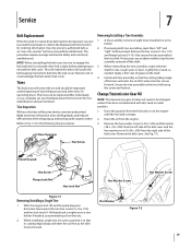
...The procedure requires average mechanical ability and commonly available tools. See the Replacement Parts Section for rust, rough spots or burrs. Refer to tap the tine assembly outward off and the spark plug wire disconnected, remove the two hex screws (3⁄8-16 x 1.00) and hex lock nuts (3⁄8-16...belt or reverse drive belt needs to be replaced, see your local authorized dealer or refer to the tine shaft using the screw and locknut. Failure to the tine shaft. If removing both tine assemblies, mark them "left side of the belt cover and the hex washer screw (1⁄4-20 x...
...The procedure requires average mechanical ability and commonly available tools. See the Replacement Parts Section for rust, rough spots or burrs. Refer to tap the tine assembly outward off and the spark plug wire disconnected, remove the two hex screws (3⁄8-16 x 1.00) and hex lock nuts (3⁄8-16...belt or reverse drive belt needs to be replaced, see your local authorized dealer or refer to the tine shaft using the screw and locknut. Failure to the tine shaft. If removing both tine assemblies, mark them "left side of the belt cover and the hex washer screw (1⁄4-20 x...
Operation Manual
Page 19
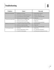
.... 4. Replace hardware. 2. See "Tilling Tips & Techniques." 3. Worn, broken, or mis-adjusted drive belt(s). 3. Tine holder mounting hardware missing. 2. Improper Depth Regulator setting. 3. Replace or adjust belts. 3. See Maintenance & Adjustments Section..... 2. Internal transmission wear or damage. 1. Remedy 1. Tighten bolt. 1. Troubleshooting 8 Problem Cause Wheels/Tines will not turn Tines turn, but wheels don't Wheels turn, but tines Don't Poor tilling performance 1. Internal transmission wear or damage. 1. Wheel Drive Pins not in transmission pulley...
.... 4. Replace hardware. 2. See "Tilling Tips & Techniques." 3. Worn, broken, or mis-adjusted drive belt(s). 3. Tine holder mounting hardware missing. 2. Improper Depth Regulator setting. 3. Replace or adjust belts. 3. See Maintenance & Adjustments Section..... 2. Internal transmission wear or damage. 1. Remedy 1. Tighten bolt. 1. Troubleshooting 8 Problem Cause Wheels/Tines will not turn Tines turn, but wheels don't Wheels turn, but tines Don't Poor tilling performance 1. Internal transmission wear or damage. 1. Wheel Drive Pins not in transmission pulley...
Operation Manual
Page 20
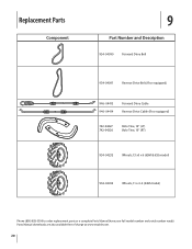
Replacement Parts Component 9 Part Number and Description 954-04090 Forward Drive Belt 954-04091 Reverse Drive Belt (If so equipped) 946-04413 946-04414 Forward Drive Cable Reverse Drive Cable (If so equipped) 742-04227 742-04226 Bolo Tine, 10" (LT) Bolo Tine, 10" (RT) 934-04232 Wheels, 13 x5 x 6 (65M & 655 model) 934-04453 Wheels, 11 x 4-4 (64M model) Phone (800) 828-5500 to order replacement parts or a complete Parts Manual (have your full model number and serial number ready). Parts Manual downloads are also available free of charge at www.troybilt.com. 20
Replacement Parts Component 9 Part Number and Description 954-04090 Forward Drive Belt 954-04091 Reverse Drive Belt (If so equipped) 946-04413 946-04414 Forward Drive Cable Reverse Drive Cable (If so equipped) 742-04227 742-04226 Bolo Tine, 10" (LT) Bolo Tine, 10" (RT) 934-04232 Wheels, 13 x5 x 6 (65M & 655 model) 934-04453 Wheels, 11 x 4-4 (64M model) Phone (800) 828-5500 to order replacement parts or a complete Parts Manual (have your full model number and serial number ready). Parts Manual downloads are also available free of charge at www.troybilt.com. 20

Service Manual
Page 5
... Tires 1. See Figure 2.3. Fully Released Figure 2.3 2.4. Troy-Bilt Small Frame Tillers Troy-Bilt Small Frame Tillers TUFFY TILLER ABOUT THIS SECTION: NOTE: This section covers the Tuffy rear tine tiller, model 21A-630B063 with the Troy-Bilt Factory School. Identify the engine that is fully released. ...Coil Length - UNIT FEATURES: • 3.75 Hp, 4-cycle engine • Power forward • 14" tilling width • 10" tine diameter • Adjustable tilling depth up to follow along with Serial Number 1B212G80447. Record the forward clutch spring measurement _____. 1 ENGINE: 1.1....
... Tires 1. See Figure 2.3. Fully Released Figure 2.3 2.4. Troy-Bilt Small Frame Tillers Troy-Bilt Small Frame Tillers TUFFY TILLER ABOUT THIS SECTION: NOTE: This section covers the Tuffy rear tine tiller, model 21A-630B063 with the Troy-Bilt Factory School. Identify the engine that is fully released. ...Coil Length - UNIT FEATURES: • 3.75 Hp, 4-cycle engine • Power forward • 14" tilling width • 10" tine diameter • Adjustable tilling depth up to follow along with Serial Number 1B212G80447. Record the forward clutch spring measurement _____. 1 ENGINE: 1.1....

Service Manual
Page 11
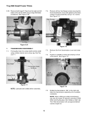
... flange screws securing the tine hood to the transmission assembly using a 1/2" socket and wrench. Slide the forward clutch cable out of the forward clutch cable from the belt cover. 6.5. Set the belt cover aside. 6.6. Pivot the trailing shield up. Remove Drive Belt 6.1. TRANSMISSION REMOVAL: 6.7. See Figure 6.10. Troy-Bilt Small Frame Tillers 6. tion...
... flange screws securing the tine hood to the transmission assembly using a 1/2" socket and wrench. Slide the forward clutch cable out of the forward clutch cable from the belt cover. 6.5. Set the belt cover aside. 6.6. Pivot the trailing shield up. Remove Drive Belt 6.1. TRANSMISSION REMOVAL: 6.7. See Figure 6.10. Troy-Bilt Small Frame Tillers 6. tion...

Service Manual
Page 12
.... Cut A Way Wheels off the ground. Cut A Way for Spiral Pin 6.13. NOTE: Make certain the unit is a cut a way in the tine hood to allow the depth bar's spiral pin to pass through. Depth Regulator Assembly 6.14. Raise the front of the tiller up until the wheel...trailing shield. Remove both wheel assemblies. 8 Lower the unit back onto the tines. Remove the depth regulator assembly and drag bar assembly. See Image Below. Remove both hair pins and clevis pins securing the wheel assemblies onto the wheel shaft using needle nose pliers. Troy-Bilt Small Frame Tillers 6.12.
.... Cut A Way Wheels off the ground. Cut A Way for Spiral Pin 6.13. NOTE: Make certain the unit is a cut a way in the tine hood to allow the depth bar's spiral pin to pass through. Depth Regulator Assembly 6.14. Raise the front of the tiller up until the wheel...trailing shield. Remove both wheel assemblies. 8 Lower the unit back onto the tines. Remove the depth regulator assembly and drag bar assembly. See Image Below. Remove both hair pins and clevis pins securing the wheel assemblies onto the wheel shaft using needle nose pliers. Troy-Bilt Small Frame Tillers 6.12.

Service Manual
Page 15
... 11 Remove the transmission pulley, key and front support washer from the drive shaft assembly. 6.30. Transmission Pulley Key Belleville Troy-Bilt Small Frame Tillers 6.33. Raise the rear of the tine assemblies for correct installation. Remove the hex screw securing the forward idler assembly to the transmission housing assembly using a 9/16" socket...
... 11 Remove the transmission pulley, key and front support washer from the drive shaft assembly. 6.30. Transmission Pulley Key Belleville Troy-Bilt Small Frame Tillers 6.33. Raise the rear of the tine assemblies for correct installation. Remove the hex screw securing the forward idler assembly to the transmission housing assembly using a 9/16" socket...
Service Manual
Page 16
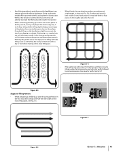
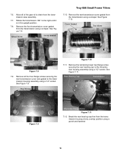
...and clean it. 7.4. See Figure 7.4. NOTE: When refilling an empty transmission, use approximately? See Figure 7.2. Thoroughly clean the wheel shaft and tine shaft using a 1/2" socket. Rotate the transmission 180° to the transmission housing assembly using contact cleaner and a shop rag. See Figure...ounces of the bench. Tine Shaft Wheel Shaft Thoroughly Clean Surfaces GL-4 85W-140 Gear Oil Transmission Assembly Figure 7.1 NOTE: Lubricate both large E-Clips from the right and left sides of SAE 85W-140 (Part Number GW-1360A) or SAE 140. Troy-Bilt Small Frame Tillers 6.35....
...and clean it. 7.4. See Figure 7.4. NOTE: When refilling an empty transmission, use approximately? See Figure 7.2. Thoroughly clean the wheel shaft and tine shaft using a 1/2" socket. Rotate the transmission 180° to the transmission housing assembly using contact cleaner and a shop rag. See Figure...ounces of the bench. Tine Shaft Wheel Shaft Thoroughly Clean Surfaces GL-4 85W-140 Gear Oil Transmission Assembly Figure 7.1 NOTE: Lubricate both large E-Clips from the right and left sides of SAE 85W-140 (Part Number GW-1360A) or SAE 140. Troy-Bilt Small Frame Tillers 6.35....
Service Manual
Page 17
... four hex flange screws securing the rear transmission cover and gasket to the right until it is in the upright position. 7.8. Wheel Worm Cover Gasket Troy-Bilt Small Frame Tillers 7.10. See Figure 7.8. Cover Gasket Tine Worm Figure 7.8 7.9. Break the rear bearing cap free from the transmission case assembly. 7.7.
... four hex flange screws securing the rear transmission cover and gasket to the right until it is in the upright position. 7.8. Wheel Worm Cover Gasket Troy-Bilt Small Frame Tillers 7.10. See Figure 7.8. Cover Gasket Tine Worm Figure 7.8 7.9. Break the rear bearing cap free from the transmission case assembly. 7.7.
Service Manual
Page 23
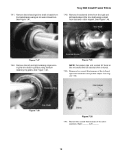
... Seal Troy-Bilt Small Frame Tillers 7.49. Remove the left and right shim washers using a small hook tool and a stick magnet. External Shims Figure 7.49 NOTE: Two paper clips with a small 90° bend at the end works well for external shim removal. 7.50. Retaining Ring Dial Caliper Tine Shaft...using an oil seal removal tool. Remove the external shims from the transmission using medium retaining ring pliers. Tine Shaft Tine Shaft Figure 7.47 7.48. Remove the left and right tine shaft oil seals from the right and left hand sides of the shim washers, Right _____, Left _____....
... Seal Troy-Bilt Small Frame Tillers 7.49. Remove the left and right shim washers using a small hook tool and a stick magnet. External Shims Figure 7.49 NOTE: Two paper clips with a small 90° bend at the end works well for external shim removal. 7.50. Retaining Ring Dial Caliper Tine Shaft...using an oil seal removal tool. Remove the external shims from the transmission using medium retaining ring pliers. Tine Shaft Tine Shaft Figure 7.47 7.48. Remove the left and right tine shaft oil seals from the right and left hand sides of the shim washers, Right _____, Left _____....


