Operation Manual
Page 2
...the model plate by standing at the operator's position and looking down at all models. If applicable, the power testing information used to ensure your new equipment, please locate the model plate on this manual is responsible for more information. We want to ... prior to safely and easily set up and operating your complete satisfaction at the front right corner of product specifications for purchasing a Troy-Bilt Tiller. Please refer to familiarize yourself with the machine, its features and operation. You can be necessary, should you for various models....
...the model plate by standing at the operator's position and looking down at all models. If applicable, the power testing information used to ensure your new equipment, please locate the model plate on this manual is responsible for more information. We want to ... prior to safely and easily set up and operating your complete satisfaction at the front right corner of product specifications for purchasing a Troy-Bilt Tiller. Please refer to familiarize yourself with the machine, its features and operation. You can be necessary, should you for various models....

Operation Manual
Page 4
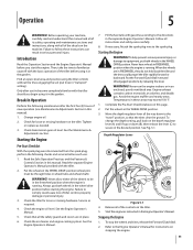
...moving parts have stopped. g. Allow engine to cool at least five minutes before refueling. Contact with safety devices. If this manual, use care and good judgement. Start the engine according to a complete stop engine before starting the engine. Disengage all times until the tines ...remove gas cap or add fuel while the engine is complete. j. Operation 1. Be careful when tilling in the ground and propel the tiller forward. Do not carry passengers. 7. Exercise caution to allow space for assistance and the name of the fuel tank or container opening ...
...moving parts have stopped. g. Allow engine to cool at least five minutes before refueling. Contact with safety devices. If this manual, use care and good judgement. Start the engine according to a complete stop engine before starting the engine. Disengage all times until the tines ...remove gas cap or add fuel while the engine is complete. j. Operation 1. Be careful when tilling in the ground and propel the tiller forward. Do not carry passengers. 7. Exercise caution to allow space for assistance and the name of the fuel tank or container opening ...
Operation Manual
Page 8
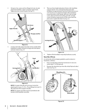
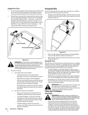
.... There are 3-4" into place and re-tighten the knob. Tighten all the handlebar mounting hardware securely. Move Tiller Off Crate To roll the tiller off the ground. 2. Upper Handle Hex Screw Flange Lock Nut Knob Handle Support Carriage Screw Figure 3-2 3.... Remove the wheel drive pin from the wheel hub and wheel shaft. Loosely attach the support brackets to the desired setting, push the carriage screw in until the square portion of the handlebar assembly using...
.... There are 3-4" into place and re-tighten the knob. Tighten all the handlebar mounting hardware securely. Move Tiller Off Crate To roll the tiller off the ground. 2. Upper Handle Hex Screw Flange Lock Nut Knob Handle Support Carriage Screw Figure 3-2 3.... Remove the wheel drive pin from the wheel hub and wheel shaft. Loosely attach the support brackets to the desired setting, push the carriage screw in until the square portion of the handlebar assembly using...
Operation Manual
Page 9
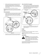
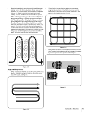
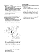
... (If so equipped) 1. See Fig. 3-7. Z-Connector Cable Bracket Cable Bracket Figure 3-6 2. Set-Up Tire Pressure Check the air pressure with your tiller. Deflate or inflate the tires equally to a flat area. Gasoline is hot or running. Service the engine with the other sources of the cable bracket...shaft only (not through wheel hubs and wheel shaft). The wheel should now spin freely (freewheel) on the wheel shaft . Use the handlebar to roll the tiller to between 15 and 20 PSI. Carefully unwrap the forward clutch cable from its shipping position. See Fig. 3-6. Pull the ...
... (If so equipped) 1. See Fig. 3-7. Z-Connector Cable Bracket Cable Bracket Figure 3-6 2. Set-Up Tire Pressure Check the air pressure with your tiller. Deflate or inflate the tires equally to a flat area. Gasoline is hot or running. Service the engine with the other sources of the cable bracket...shaft only (not through wheel hubs and wheel shaft). The wheel should now spin freely (freewheel) on the wheel shaft . Use the handlebar to roll the tiller to between 15 and 20 PSI. Carefully unwrap the forward clutch cable from its shipping position. See Fig. 3-6. Pull the ...
Operation Manual
Page 11
...in this manual). 1. WARNING! Engine exhaust contains carbon monoxide, an odorless and deadly gas. Complete the Pre-Start Checklist above on the tiller. Release all of tiller control, property damage or personal injury. 3. To stop the wheels and tines, release the Forward Clutch Bail. 2. Tighten or replace as ... Engine Pre-Start Checklist With the spark plug wire disconnected from the spark plug, perform the following maintenance after you begin using the tiller controls without the tines engaging the soil (put both wheels in the garden. Find an open, level area and practice...
...in this manual). 1. WARNING! Engine exhaust contains carbon monoxide, an odorless and deadly gas. Complete the Pre-Start Checklist above on the tiller. Release all of tiller control, property damage or personal injury. 3. To stop the wheels and tines, release the Forward Clutch Bail. 2. Tighten or replace as ... Engine Pre-Start Checklist With the spark plug wire disconnected from the spark plug, perform the following maintenance after you begin using the tiller controls without the tines engaging the soil (put both wheels in the garden. Find an open, level area and practice...
Operation Manual
Page 12
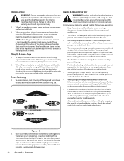
... more deeply. Operation Figure 5-3 2. Do not till near buried electric cables, telephone lines, pipes or hoses. • This is a CRT (counter-rotating tine) tiller. As the wheels pull forward, the tines rotate backward. WARNING! Section 5- See Fig. 5-2. Clearing the Tines The tines have a self-clearing action ...models without reverse handle: • Release the forward clutch bail. Also, try to till under crop residues or cover crops while they are used on the handlebars to try to 12"). Walk behind and exercise caution when operating in freewheel.
... more deeply. Operation Figure 5-3 2. Do not till near buried electric cables, telephone lines, pipes or hoses. • This is a CRT (counter-rotating tine) tiller. As the wheels pull forward, the tines rotate backward. WARNING! Section 5- See Fig. 5-2. Clearing the Tines The tines have a self-clearing action ...models without reverse handle: • Release the forward clutch bail. Also, try to till under crop residues or cover crops while they are used on the handlebars to try to 12"). Walk behind and exercise caution when operating in freewheel.
Operation Manual
Page 13
... destroy weeds, see Fig. 5-4), Adjust the tines to dig only 1" to 2" deep. See Fig. 5-5. 3 Figure 5-7 Figure 5-5 Section 5 - Using shallow tilling depths helps prevent injury to the plants whose roots often grow close to the surface. Operation 13 best results (in Fig. 5-6. Overlap each... final, deep tilling pass. Figure 5-6 • If the garden size will passes to thoroughly pulverize the soil.) attempt to propel the tiller backward, towards the operator. • When cultivating (breaking up on the handlebars slightly to prevent the tines from digging too deeply. (...
... destroy weeds, see Fig. 5-4), Adjust the tines to dig only 1" to 2" deep. See Fig. 5-5. 3 Figure 5-7 Figure 5-5 Section 5 - Using shallow tilling depths helps prevent injury to the plants whose roots often grow close to the surface. Operation 13 best results (in Fig. 5-6. Overlap each... final, deep tilling pass. Figure 5-6 • If the garden size will passes to thoroughly pulverize the soil.) attempt to propel the tiller backward, towards the operator. • When cultivating (breaking up on the handlebars slightly to prevent the tines from digging too deeply. (...
Operation Manual
Page 14
...Go back and forth across the first row as possible (the less incline to control the speed of each terrace. Also, use the blocks to temporarily keep the tiller in the wheel drive position. NOTE: when tilling on a slope allows maximum planting area and also leaves room for any handlers... in Fig. 5-8. Two or more people are needed to make the first pass uphill as the tiller could result in personal injury. 1. Two or more people should share the load. • Use sturdy ramps and manually - Each succeeding lower terrace is too heavy and bulky to follow these guidelines...
...Go back and forth across the first row as possible (the less incline to control the speed of each terrace. Also, use the blocks to temporarily keep the tiller in the wheel drive position. NOTE: when tilling on a slope allows maximum planting area and also leaves room for any handlers... in Fig. 5-8. Two or more people are needed to make the first pass uphill as the tiller could result in personal injury. 1. Two or more people should share the load. • Use sturdy ramps and manually - Each succeeding lower terrace is too heavy and bulky to follow these guidelines...
Operation Manual
Page 15
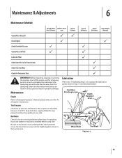
...30 Hours See Engine Manual Check Motor Oil Level PP Clean Engine P P Check Drive Belt Tension P P Check Nuts and Bolts P P Lubricate Tiller P Check Gear Oil Level in Transmission P Check Tines for Wear P Check Air Pressure in Fig. 6-1 and described below. Before inspecting, cleaning ...for loose or missing hardware after every 10 operating hours and tighten or replace (as needed) before using tiller Be sure to check the screws underneath the tiller hood that secure the transmission cover and the Depth Regulator Lever to the transmission. Handlebar Attaching Screws Depth...
...30 Hours See Engine Manual Check Motor Oil Level PP Clean Engine P P Check Drive Belt Tension P P Check Nuts and Bolts P P Lubricate Tiller P Check Gear Oil Level in Transmission P Check Tines for Wear P Check Air Pressure in Fig. 6-1 and described below. Before inspecting, cleaning ...for loose or missing hardware after every 10 operating hours and tighten or replace (as needed) before using tiller Be sure to check the screws underneath the tiller hood that secure the transmission cover and the Depth Regulator Lever to the transmission. Handlebar Attaching Screws Depth...
Operation Manual
Page 16
... of operation or whenever you notice any rust, burrs or rough spots (especially around the oil fill plug. Off-Season Storage When the tiller won't be used for loose parts and hardware. 3. The gear oil level is correct if the gear oil is okay, securely replace the oil fill plug... severe damage. Clean the tiller and engine. 2. Apply grease to the wheel shaft. • Grease the back, front and sides of the shaft before installing the tines. • Oil the threads on the drive shaft. 9. Gear oil will provide an incorrect oil level reading. 2. Use a clean lubricating oil ...
... of operation or whenever you notice any rust, burrs or rough spots (especially around the oil fill plug. Off-Season Storage When the tiller won't be used for loose parts and hardware. 3. The gear oil level is correct if the gear oil is okay, securely replace the oil fill plug... severe damage. Clean the tiller and engine. 2. Apply grease to the wheel shaft. • Grease the back, front and sides of the shaft before installing the tines. • Oil the threads on the drive shaft. 9. Gear oil will provide an incorrect oil level reading. 2. Use a clean lubricating oil ...
Operation Manual
Page 17
... the shaft. 4. Lightly file or sand, as needed , use a rubber mallet to the tine shaft using the screw and locknut. See Fig. 7-2. With the engine shut off the shaft. 3. Use only a factory-authorized belt as the tiller moves forward. the-counter" belt may not perform satisfactorily. The... x .500) from the left " and "right" before attempting to be changed unless it has been contaminated with use , the tines will enter the soil first when the tiller moves forward. Hex Washer Screw Hex Washer Screw Flat Washer Figure 7-2 17 See the Replacement Parts Section for rust, ...
... the shaft. 4. Lightly file or sand, as needed , use a rubber mallet to the tine shaft using the screw and locknut. See Fig. 7-2. With the engine shut off the shaft. 3. Use only a factory-authorized belt as the tiller moves forward. the-counter" belt may not perform satisfactorily. The... x .500) from the left " and "right" before attempting to be changed unless it has been contaminated with use , the tines will enter the soil first when the tiller moves forward. Hex Washer Screw Hex Washer Screw Flat Washer Figure 7-2 17 See the Replacement Parts Section for rust, ...

Operation Manual
Page 24
... all gears, shafts and housings) against defects in material and workmanship for the life of the tiller, to obtain warranty coverage. Check your Yellow Pages, or contact Troy-Bilt LLC at www.troybilt.com. Replacement parts that are not limited to state. h. The provisions ... years commencing on the date of original purchase and will void your warranty as to any product, shall bind Troy-Bilt. Troy-Bilt warrants attachments for this product for commercial use or exposure. This limited warranty does not provide coverage in material and workmanship for a period of thirty (30...
... all gears, shafts and housings) against defects in material and workmanship for the life of the tiller, to obtain warranty coverage. Check your Yellow Pages, or contact Troy-Bilt LLC at www.troybilt.com. Replacement parts that are not limited to state. h. The provisions ... years commencing on the date of original purchase and will void your warranty as to any product, shall bind Troy-Bilt. Troy-Bilt warrants attachments for this product for commercial use or exposure. This limited warranty does not provide coverage in material and workmanship for a period of thirty (30...

Service Manual
Page 5
Troy-Bilt Small Frame Tillers Troy-Bilt Small Frame Tillers TUFFY TILLER ABOUT THIS SECTION: NOTE: This section covers the Tuffy rear tine tiller, model 21A-630B063 with the forward clutch bail fully released using a dial caliper. UNIT FEATURES: • 3.75 Hp, 4-cycle engine • Power forward • 14" tilling width • 10" tine diameter • Adjustable tilling depth up...
Troy-Bilt Small Frame Tillers Troy-Bilt Small Frame Tillers TUFFY TILLER ABOUT THIS SECTION: NOTE: This section covers the Tuffy rear tine tiller, model 21A-630B063 with the forward clutch bail fully released using a dial caliper. UNIT FEATURES: • 3.75 Hp, 4-cycle engine • Power forward • 14" tilling width • 10" tine diameter • Adjustable tilling depth up...

Service Manual
Page 6
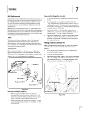
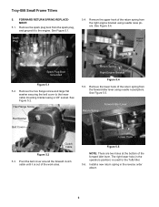
... adjustment screw. 2.14. Release the forward clutch cable. 2.12. Loosen the hex jam nut securing the clutch cable assembly in position using a 3/8" wrench and a small adjustable wrench. Measure the overall length of the forward clutch is too short (less than the first measurement... Un-thread the hex jam nut until the proper adjustment has been achieved. Hex Jam Nut Loosened Clutch Bail Upper Handle Figure 2.5 2.6. Troy-Bilt Small Frame Tillers 2.5. Jam Nut Rotate Hold Forward Clutch Cable Figure 2.14 2 See Figure 2.12. See Figure 2.14. If the second measurement (spring...
... adjustment screw. 2.14. Release the forward clutch cable. 2.12. Loosen the hex jam nut securing the clutch cable assembly in position using a 3/8" wrench and a small adjustable wrench. Measure the overall length of the forward clutch is too short (less than the first measurement... Un-thread the hex jam nut until the proper adjustment has been achieved. Hex Jam Nut Loosened Clutch Bail Upper Handle Figure 2.5 2.6. Troy-Bilt Small Frame Tillers 2.5. Jam Nut Rotate Hold Forward Clutch Cable Figure 2.14 2 See Figure 2.12. See Figure 2.14. If the second measurement (spring...
Service Manual
Page 7
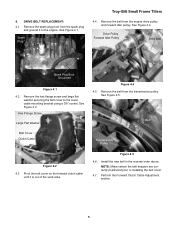
... Plug Boot Grounded Lower Handle Bracket Figure 3.1 Forward Clutch Cable Figure 3.4 3 Spark Plug Troy-Bilt Small Frame Tillers 3.2. Perform the forward clutch spring measurement procedures to the engine. Remove the spark plug boot from the spark plug, and ground it counter-clockwise (away from the lower handle bracket using a 3/8" wrench and a small adjustable wrench.
... Plug Boot Grounded Lower Handle Bracket Figure 3.1 Forward Clutch Cable Figure 3.4 3 Spark Plug Troy-Bilt Small Frame Tillers 3.2. Perform the forward clutch spring measurement procedures to the engine. Remove the spark plug boot from the spark plug, and ground it counter-clockwise (away from the lower handle bracket using a 3/8" wrench and a small adjustable wrench.
Service Manual
Page 8
Troy-Bilt Small Frame Tillers 3.5. See Figure 3.10. Slide the belt cover down the... Idler Lever Belt Cover Z Fitting Figure 3.6 3.7. Remove the lower cable tie securing the forward clutch cable to the lower handlebar using a 3/8" wrench and a 7/16" wrench. Cable Tie 3.8. See Figure 3.6. Hex Flange Screw Figure 3.8 3.9. See Figure ...3.5. Loosen the hex jam nut securing the forward clutch cable to the lower cable mounting bracket using a 3/8" socket. See Figure 3.8. Remove the lower portion of the work area. NOTE: The upper portion of the...
Troy-Bilt Small Frame Tillers 3.5. See Figure 3.10. Slide the belt cover down the... Idler Lever Belt Cover Z Fitting Figure 3.6 3.7. Remove the lower cable tie securing the forward clutch cable to the lower handlebar using a 3/8" wrench and a 7/16" wrench. Cable Tie 3.8. See Figure 3.6. Hex Flange Screw Figure 3.8 3.9. See Figure ...3.5. Loosen the hex jam nut securing the forward clutch cable to the lower cable mounting bracket using a 3/8" socket. See Figure 3.8. Remove the lower portion of the work area. NOTE: The upper portion of the...
Service Manual
Page 9
... installing the belt cover. 4.7. NOTE: Make certain the belt keepers are correctly positioned prior to the lower cable mounting bracket using a 3/8" socket. 4. DRIVE BELT REPLACEMENT: 4.1. See Figure 4.5. Spark Plug Troy-Bilt Small Frame Tillers 4.4. See Figure 4.2. Hex Flange Screw Large Flat Washer Belt Cover Clutch Cable Figure 4.4 4.5. Remove the belt from the spark plug...
... installing the belt cover. 4.7. NOTE: Make certain the belt keepers are correctly positioned prior to the lower cable mounting bracket using a 3/8" socket. 4. DRIVE BELT REPLACEMENT: 4.1. See Figure 4.5. Spark Plug Troy-Bilt Small Frame Tillers 4.4. See Figure 4.2. Hex Flange Screw Large Flat Washer Belt Cover Clutch Cable Figure 4.4 4.5. Remove the belt from the spark plug...
Service Manual
Page 10
...Hook Figure 5.5 NOTE: There are two holes at the bottom of the return spring from the forward idler lever using needle nosed pliers. Remove the lower hook of the work area. The right lower hole (in the reverse order...return spring in the operators position) is out of the return spring from the right engine bracket using a 3/8" socket. FORWARD RETURN SPRING REPLACEMENT: 5.1. Pivot the belt cover around the forward clutch cable until it to... Figure 5.2. Remove the spark plug boot from the spark plug, and ground it is used for the Tuffy tiller. 5.6. Troy-Bilt Small Frame...
...Hook Figure 5.5 NOTE: There are two holes at the bottom of the return spring from the forward idler lever using needle nosed pliers. Remove the lower hook of the work area. The right lower hole (in the reverse order...return spring in the operators position) is out of the return spring from the right engine bracket using a 3/8" socket. FORWARD RETURN SPRING REPLACEMENT: 5.1. Pivot the belt cover around the forward clutch cable until it to... Figure 5.2. Remove the spark plug boot from the spark plug, and ground it is used for the Tuffy tiller. 5.6. Troy-Bilt Small Frame...

Service Manual
Page 11
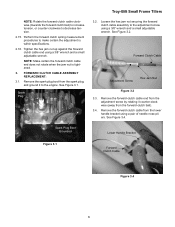
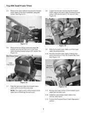
... Screw Figure 6.10 6.11. Remove both self tapping hex flange screws securing the tine hood to the transmission assembly using a 3/8" wrench and a 7/16" wrench. 6.2. performing this section. See Figure 6.10. Troy-Bilt Small Frame Tillers 6. Remove Drive Belt 6.1. Secure the handlebar from the forward idler lever. 6.4. Loosen the hex nut securing the forward clutch...
... Screw Figure 6.10 6.11. Remove both self tapping hex flange screws securing the tine hood to the transmission assembly using a 3/8" wrench and a 7/16" wrench. 6.2. performing this section. See Figure 6.10. Troy-Bilt Small Frame Tillers 6. Remove Drive Belt 6.1. Secure the handlebar from the forward idler lever. 6.4. Loosen the hex nut securing the forward clutch...

Service Manual
Page 12
... front of the tiller up until the wheel assemblies are off Ground Raise the Unit Up Figure 6.14 6.15. Cut A Way Wheels off the ground. Cut A Way for Spiral Pin 6.13. Remove both hair pins and clevis pins securing the wheel assemblies onto the wheel shaft using needle nose pliers... certain the unit is a cut a way in the tine hood to allow the depth bar's spiral pin to pass through. See Figure 6.15. Troy-Bilt Small Frame Tillers 6.12. Depth Regulator Assembly 6.14. See Figure 6.14. See Image Below. Lower the unit back onto the tines. Hair Pin Clevis Pin Figure...
... front of the tiller up until the wheel assemblies are off Ground Raise the Unit Up Figure 6.14 6.15. Cut A Way Wheels off the ground. Cut A Way for Spiral Pin 6.13. Remove both hair pins and clevis pins securing the wheel assemblies onto the wheel shaft using needle nose pliers... certain the unit is a cut a way in the tine hood to allow the depth bar's spiral pin to pass through. See Figure 6.15. Troy-Bilt Small Frame Tillers 6.12. Depth Regulator Assembly 6.14. See Figure 6.14. See Image Below. Lower the unit back onto the tines. Hair Pin Clevis Pin Figure...


