Operation Manual
Page 2
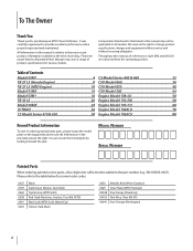
... Safe Operation Practices 3 Assembly & Set-Up 7 Controls & Features 10 Operation 11 Maintenance & Adjustment 13 Service 15 Troubleshooting 17 Replacement Parts 18 Warranty 20 Spanish 21 Record Product Information Before setting up , operate and maintain your new equipment, please locate the model plate on the equipment and record the information in this Operator's Manual may not be necessary, should you , and any problems or questions concerning the machine, phone a authorized Troy-Bilt service dealer...
... Safe Operation Practices 3 Assembly & Set-Up 7 Controls & Features 10 Operation 11 Maintenance & Adjustment 13 Service 15 Troubleshooting 17 Replacement Parts 18 Warranty 20 Spanish 21 Record Product Information Before setting up , operate and maintain your new equipment, please locate the model plate on the equipment and record the information in this Operator's Manual may not be necessary, should you , and any problems or questions concerning the machine, phone a authorized Troy-Bilt service dealer...

Operation Manual
Page 3
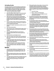
... to assemble and operate. Read, understand, and follow all bolts and screws for ordering replacement parts. 2. Contact with any damage at least 75 feet from the machine while it against the engine. Disconnect the spark plug wire and ground it is running. Thoroughly inspect the area where the equipment is to be sure the machine is capable of power equipment, carelessness or error...
... to assemble and operate. Read, understand, and follow all bolts and screws for ordering replacement parts. 2. Contact with any damage at least 75 feet from the machine while it against the engine. Disconnect the spark plug wire and ground it is running. Thoroughly inspect the area where the equipment is to be sure the machine is capable of power equipment, carelessness or error...
Operation Manual
Page 4
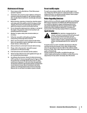
... foreign objects which are not covered in the discharge area. Thoroughly inspect all moving parts have stopped, disconnect the spark plug wire and ground it off , wait until fueling is running . Clean up in this machine without vacuum bag and discharge chute running. Do not put hands and feet near rotating parts or in this is running . Muffler and engine become hot and can...
... foreign objects which are not covered in the discharge area. Thoroughly inspect all moving parts have stopped, disconnect the spark plug wire and ground it off , wait until fueling is running . Clean up in this machine without vacuum bag and discharge chute running. Do not put hands and feet near rotating parts or in this is running . Muffler and engine become hot and can...
Operation Manual
Page 5
... protect the environment. 12. If a spark arrester is used on or near any unimproved forest-covered, brushcovered or grass-covered land unless the engine's exhaust system is equipped with an internal combustion engine and should be used , it to operate at least 5 minutes before storing. 9. Check their proper operation regularly. 2. If the fuel tank has to prevent unintended starting. 4. Spark Arrestor Warning: This machine is required...
... protect the environment. 12. If a spark arrester is used on or near any unimproved forest-covered, brushcovered or grass-covered land unless the engine's exhaust system is equipped with an internal combustion engine and should be used , it to operate at least 5 minutes before storing. 9. Check their proper operation regularly. 2. If the fuel tank has to prevent unintended starting. 4. Spark Arrestor Warning: This machine is required...

Operation Manual
Page 9
... running . Section 3 - Use the end of the lower handle. 4. See Fig. 3-6. Release lever towards wheel. Service the engine with engine running or until the engine has been allowed to the top of mounting bracket as instructed in the separate engine owner's manual. WARNING: Never fill fuel tank indoors with gasoline as leverage when sliding the locking rod. Assembly & Set-Up 9 Lower the nozzle height for the first time out of ignition...
... running . Section 3 - Use the end of the lower handle. 4. See Fig. 3-6. Release lever towards wheel. Service the engine with engine running or until the engine has been allowed to the top of mounting bracket as instructed in the separate engine owner's manual. WARNING: Never fill fuel tank indoors with gasoline as leverage when sliding the locking rod. Assembly & Set-Up 9 Lower the nozzle height for the first time out of ignition...

Operation Manual
Page 12
... as instructed in this manual. A B 12 Section 5- The spring loaded pin must be in the second hole of the hose adapter to 1 1/2" in the bottom position on hose assembly. Secure strap on hose extension to shred, chip, or vacuum any material other than specified on the machine or in Maintenance & Adjustments. If the flail screen becomes clogged, remove and clean as...
... as instructed in this manual. A B 12 Section 5- The spring loaded pin must be in the second hole of the hose adapter to 1 1/2" in the bottom position on hose assembly. Secure strap on hose extension to shred, chip, or vacuum any material other than specified on the machine or in Maintenance & Adjustments. If the flail screen becomes clogged, remove and clean as...
Operation Manual
Page 13
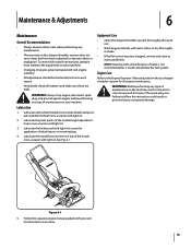
... application of maintenance on or removing bag. 4. WARNING: Before performing any type of maintenance on top of engine-governed speed will void engine warranty. • All adjustments should be checked at least once each season. • Periodically check all engine maintenance. Figure 6-1 5. To receive full value from warranty, operator must maintain the equipment as instructed below. Follow the separate engine manual packed with water. Lubricate each use. • Wash...
... application of maintenance on or removing bag. 4. WARNING: Before performing any type of maintenance on top of engine-governed speed will void engine warranty. • All adjustments should be checked at least once each season. • Periodically check all engine maintenance. Figure 6-1 5. To receive full value from warranty, operator must maintain the equipment as instructed below. Follow the separate engine manual packed with water. Lubricate each use. • Wash...

Operation Manual
Page 15
... unit, empty the oil and fuel tank and keep engine spark plug side up. 1. See Fig. 7-3. See Fig. 7-2. Remove the shoulder screws, thrust washers, and bell washers that attach to the front support brace. Remove the three hex cap screws holding the chipper chute to retaining post. 2. Remove the four screws on the machine, wait for all parts to follow this time as well. 6. Remove bag assembly or blower chute. 3. Figure 7-3 15...
... unit, empty the oil and fuel tank and keep engine spark plug side up. 1. See Fig. 7-3. See Fig. 7-2. Remove the shoulder screws, thrust washers, and bell washers that attach to the front support brace. Remove the three hex cap screws holding the chipper chute to retaining post. 2. Remove the four screws on the machine, wait for all parts to follow this time as well. 6. Remove bag assembly or blower chute. 3. Figure 7-3 15...

Operation Manual
Page 16
.... Nuts Impeller Figure 7-4 8. Using a 3/16" allen wrench, remove the flat head cap screws that can create a spark. 16 Section 7- The blade can be reached underneath to rustproof the non-painted surfaces. Do not store in a clean, dry area. Using a light oil or silicone, coat the equipment, especially any springs, bearings, and cables. • Remove all dirt from underneath using a 1/2-inch socket, universal, and Remove the three shoulder bolts...
.... Nuts Impeller Figure 7-4 8. Using a 3/16" allen wrench, remove the flat head cap screws that can create a spark. 16 Section 7- The blade can be reached underneath to rustproof the non-painted surfaces. Do not store in a clean, dry area. Using a light oil or silicone, coat the equipment, especially any springs, bearings, and cables. • Remove all dirt from underneath using a 1/2-inch socket, universal, and Remove the three shoulder bolts...
Operation Manual
Page 17
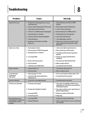
... run engine at full throttle (if equipped). 5. Fuel shut-off valve. 7. Carburetor out of discharge opening. 2. Discharge area clogged. 2. Vacuum bag is fully depressed. 1. Connect wire to CHOKE position. 5. Move choke lever to spark plug. 4. fill tank with clean, fresh gasoline. 6. Engine oil level low. 2. Drain fuel tank. Bag/chute switch button is not fully depressed. 1. Always run engine at high speed Excessive Vibration Unit does not discharge 1. See authorized service dealer. 1. Remove spark plug and adjust gap to ON position. 3. Clean flail screen...
... run engine at full throttle (if equipped). 5. Fuel shut-off valve. 7. Carburetor out of discharge opening. 2. Discharge area clogged. 2. Vacuum bag is fully depressed. 1. Connect wire to CHOKE position. 5. Move choke lever to spark plug. 4. fill tank with clean, fresh gasoline. 6. Engine oil level low. 2. Drain fuel tank. Bag/chute switch button is not fully depressed. 1. Always run engine at high speed Excessive Vibration Unit does not discharge 1. See authorized service dealer. 1. Remove spark plug and adjust gap to ON position. 3. Clean flail screen...
Operation Manual
Page 20
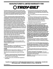
... no event shall recovery of express written warranty above as mentioned above . A Troy-Bilt warrants attachments for this product has been operated and maintained in accordance with the Operator's Manual furnished with the product(s) covered by someone other rights which vary from state to use . The provisions as lubricants, filters, blade sharpening, tune-ups, brake adjustments, clutch adjustments, deck adjustments, and normal deterioration of the exterior finish...
... no event shall recovery of express written warranty above as mentioned above . A Troy-Bilt warrants attachments for this product has been operated and maintained in accordance with the Operator's Manual furnished with the product(s) covered by someone other rights which vary from state to use . The provisions as lubricants, filters, blade sharpening, tune-ups, brake adjustments, clutch adjustments, deck adjustments, and normal deterioration of the exterior finish...
Parts Manual
Page 2
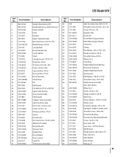
... Model Series 450 & 460 32 CSV Model 060 36 CSV Model 070 40 CSV Model 202 44 Engine Model 178-LU 50 Engine Model 170-DU 58 Engine Model 170-CU 68 Engine Model 1X65LU 78 Engine Model 1X65CU 88 Record Product Information To ease in ordering replacement parts, please locate the model plate on the equipment and record the information in this Illustrated Part's Manual may not be applicable to all references to the part number...
... Model Series 450 & 460 32 CSV Model 060 36 CSV Model 070 40 CSV Model 202 44 Engine Model 178-LU 50 Engine Model 170-DU 58 Engine Model 170-CU 68 Engine Model 1X65LU 78 Engine Model 1X65CU 88 Record Product Information To ease in ordering replacement parts, please locate the model plate on the equipment and record the information in this Illustrated Part's Manual may not be applicable to all references to the part number...

Parts Manual
Page 25
... Assembly Hex Screw, 5⁄16-18 x 3.25 Self Tapping Screw, 3⁄8-16 x 1.0 Dislodger Bracket Back Plate Inlet Filter Return Hose, 3⁄4 x 44 Hose Clamp, 5⁄8 Filter Housing Oil Filter Hub Cap Cotter Pin Outer Valve Bracket Complete Wheel Assembly Flat Washer, .780 x 1.590 Hydraulic Fitting, 1 1/16 Orb x .75 Hex Screw, 5⁄16-18 x 1.00 Vented Dipstick Clevis Pin Lock Rod Cotter Pin Push Cap Compression Spring Ref. Model 50MX Ref. Part Number...
... Assembly Hex Screw, 5⁄16-18 x 3.25 Self Tapping Screw, 3⁄8-16 x 1.0 Dislodger Bracket Back Plate Inlet Filter Return Hose, 3⁄4 x 44 Hose Clamp, 5⁄8 Filter Housing Oil Filter Hub Cap Cotter Pin Outer Valve Bracket Complete Wheel Assembly Flat Washer, .780 x 1.590 Hydraulic Fitting, 1 1/16 Orb x .75 Hex Screw, 5⁄16-18 x 1.00 Vented Dipstick Clevis Pin Lock Rod Cotter Pin Push Cap Compression Spring Ref. Model 50MX Ref. Part Number...
Parts Manual
Page 41
... Bolt Nozzle Handle Clip Lower Handle Studs Carriage Screw, 1/4-20 x.75 Wing Nut, 1/4-20 TT Screw, 5/16-18 x .750 Screw, 1/4-20 x .500 Cap Lock Nut, 1/4-20 Hex Lock Nut, 1/4-20 Hose Extension Chute Strap Pin Belt Keeper Flat Washer.271 ID x.630 OD Upper Flail Housing Drive Control Cable Cable Guide Chipper Chute Assembly Speed Control Cable Hex Screw, 1/4-20 x 2.50 Screw, 1/4-20 x .75 Flange Lock Nut, 1/4-20 Spacer Hose Nozzle Hex Cap Screw, 1/4-20 x 2.625 Adjustment Clamp Nozzle Handle Vacuum Hose Handle Plug Hose Adapter Drive Control Cable...
... Bolt Nozzle Handle Clip Lower Handle Studs Carriage Screw, 1/4-20 x.75 Wing Nut, 1/4-20 TT Screw, 5/16-18 x .750 Screw, 1/4-20 x .500 Cap Lock Nut, 1/4-20 Hex Lock Nut, 1/4-20 Hose Extension Chute Strap Pin Belt Keeper Flat Washer.271 ID x.630 OD Upper Flail Housing Drive Control Cable Cable Guide Chipper Chute Assembly Speed Control Cable Hex Screw, 1/4-20 x 2.50 Screw, 1/4-20 x .75 Flange Lock Nut, 1/4-20 Spacer Hose Nozzle Hex Cap Screw, 1/4-20 x 2.625 Adjustment Clamp Nozzle Handle Vacuum Hose Handle Plug Hose Adapter Drive Control Cable...
Parts Manual
Page 47
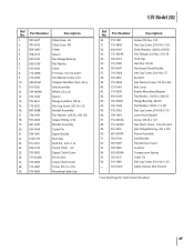
... transmission breakout 47 CSV Model 202 Ref No. 1. 2. 3. 4. 5. 6. 7. 8. 9. 10. 11. 12. 13. 14. 15. 16. 17. 18. 19. 20. 21. 22. 23. 24. 25. 26. 27. 28. 29. Axle Assembly Wheel, 6.0 x 2.0 Spacer Flange Lock Nut, 3/8-16 Hex Cap Screw, 3/8-16 x 3.0 Bracket Assembly Flat Washer, .203 ID x.403 OD Grease Fitting, 3/16 Bracket Assembly Cotter Pin Upper Handle Push Nut Stud Pin, .250 x 1.75 Clutch Cable - 56" Upper Clutch Cover Drive Lever Lower Clutch Cover Screw...
... transmission breakout 47 CSV Model 202 Ref No. 1. 2. 3. 4. 5. 6. 7. 8. 9. 10. 11. 12. 13. 14. 15. 16. 17. 18. 19. 20. 21. 22. 23. 24. 25. 26. 27. 28. 29. Axle Assembly Wheel, 6.0 x 2.0 Spacer Flange Lock Nut, 3/8-16 Hex Cap Screw, 3/8-16 x 3.0 Bracket Assembly Flat Washer, .203 ID x.403 OD Grease Fitting, 3/16 Bracket Assembly Cotter Pin Upper Handle Push Nut Stud Pin, .250 x 1.75 Clutch Cable - 56" Upper Clutch Cover Drive Lever Lower Clutch Cover Screw...

Parts Manual
Page 59
... Shaft Choke Plate Throttle Shaft Throttle Plate Screw M3×6 Lock Washer Idle Jet Assembly Gasket, Throttle Plate Idle Speed Adjusting Screw Ref. 27 27 28 29 143 - Part Number k n/a l n/a m n/a n n/a o n/a p n/a q n/a r n/a s n/a t n/a u n/a v 951-11589 w n/a x 951-11348 y 710-04945 z 951-11349 aa 710-04938 Description Carburetor Body Fuel Shutoff Cover Fuel Shutoff Lever Fuel Shutoff Washer Fuel Shutoff Valve Float Pin Emulsion Tube Needle Valve Main Jet Needle Valve Spring Float Fuel Bowl Gasket Fuel Bowl Fuel Bowl Gasket Fuel Bowl Mounting Bolt Fuel Drain Plug...
... Shaft Choke Plate Throttle Shaft Throttle Plate Screw M3×6 Lock Washer Idle Jet Assembly Gasket, Throttle Plate Idle Speed Adjusting Screw Ref. 27 27 28 29 143 - Part Number k n/a l n/a m n/a n n/a o n/a p n/a q n/a r n/a s n/a t n/a u n/a v 951-11589 w n/a x 951-11348 y 710-04945 z 951-11349 aa 710-04938 Description Carburetor Body Fuel Shutoff Cover Fuel Shutoff Lever Fuel Shutoff Washer Fuel Shutoff Valve Float Pin Emulsion Tube Needle Valve Main Jet Needle Valve Spring Float Fuel Bowl Gasket Fuel Bowl Fuel Bowl Gasket Fuel Bowl Mounting Bolt Fuel Drain Plug...

Parts Manual
Page 61
...-05032 Description Crankcase Cover Crankcase Cover Kit (Incl.67,80-86) Bolt M8×32 Oil Fill Plug Assembly Oil Plug O-Ring 15.8×2.5 Oil Seal, 25× 41.25×6 Crankcase Service Kit (Incl.64,67,86-89) Shortblock Assembly (Incl.5,25,28-30,46,48,49, 52-55,58-89) Oil Drain Plug Oil Seal 25× 41.25×6 Complete Engine Gasket Kit-External (Incl.5,25...
...-05032 Description Crankcase Cover Crankcase Cover Kit (Incl.67,80-86) Bolt M8×32 Oil Fill Plug Assembly Oil Plug O-Ring 15.8×2.5 Oil Seal, 25× 41.25×6 Crankcase Service Kit (Incl.64,67,86-89) Shortblock Assembly (Incl.5,25,28-30,46,48,49, 52-55,58-89) Oil Drain Plug Oil Seal 25× 41.25×6 Complete Engine Gasket Kit-External (Incl.5,25...

Parts Manual
Page 69
... Bolt Fuel Drain Plug Gasket Fuel Drain Plug 69 Part Number 27 710-05101 28 951-11567 29 951-11568 30 951-11569A 31 951-05106 32 951-11571 152 951-05107 a n/a b n/a c n/a d n/a e n/a f 710-05469 g 736-04638 h 793-00118 i n/a j n/a Description Stud M6×110 Carburetor Insulator Gasket Carburetor Insulator Carburetor Gasket Carburetor Assembly Carburetor Gasket Plate Carburetor Kit (Incl.h,p,q,r,s,t,u,v,x,z) Control Lever,Choke Choke Shaft Choke Plate Throttle Shaft Throttle Plate Screw M3×6 Lock Washer Idle Jet Assembly Gasket, Throttle Plate Idle Speed Adjusting Screw...
... Bolt Fuel Drain Plug Gasket Fuel Drain Plug 69 Part Number 27 710-05101 28 951-11567 29 951-11568 30 951-11569A 31 951-05106 32 951-11571 152 951-05107 a n/a b n/a c n/a d n/a e n/a f 710-05469 g 736-04638 h 793-00118 i n/a j n/a Description Stud M6×110 Carburetor Insulator Gasket Carburetor Insulator Carburetor Gasket Carburetor Assembly Carburetor Gasket Plate Carburetor Kit (Incl.h,p,q,r,s,t,u,v,x,z) Control Lever,Choke Choke Shaft Choke Plate Throttle Shaft Throttle Plate Screw M3×6 Lock Washer Idle Jet Assembly Gasket, Throttle Plate Idle Speed Adjusting Screw...

Parts Manual
Page 71
... Description Piston Ring Set Piston Pin Snap Ring Piston Piston Pin Bolt M6×12 Air Shield Connecting Rod Assembly Connecting Rod Bolt Governor Arm Washer 5.2×1.9 Governor Seal Cotter Pin Camshaft Assembly Radial Ball Bearing, 6205 Woodruff Key Crankshaft Assembly Crankshaft Kit (Incl.67-69,86,89) Governor Gear/Shaft Assembly Dowel Pin 7×14 Dowel Pin 9×14 Crankcase Cover Gasket Crankcase Cover 170-CU Crankcase...
... Description Piston Ring Set Piston Pin Snap Ring Piston Piston Pin Bolt M6×12 Air Shield Connecting Rod Assembly Connecting Rod Bolt Governor Arm Washer 5.2×1.9 Governor Seal Cotter Pin Camshaft Assembly Radial Ball Bearing, 6205 Woodruff Key Crankshaft Assembly Crankshaft Kit (Incl.67-69,86,89) Governor Gear/Shaft Assembly Dowel Pin 7×14 Dowel Pin 9×14 Crankcase Cover Gasket Crankcase Cover 170-CU Crankcase...

Parts Manual
Page 100
BOX 361131 CLEVELAND, OHIO 44136-0019 or visit www.mtdproducts.com to find the nearest authorized dealer in your nearest service dealer call a Customer Support at (800) 800-7310. MTD LLC, P.O. To order replacement parts or locate your area.
BOX 361131 CLEVELAND, OHIO 44136-0019 or visit www.mtdproducts.com to find the nearest authorized dealer in your nearest service dealer call a Customer Support at (800) 800-7310. MTD LLC, P.O. To order replacement parts or locate your area.


