
Operation Manual
Page 2
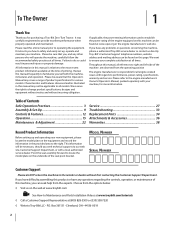
... this manual may cover a range of the seat pivot bracket. It instructs you how to performance, power-rating, specifications, warranty and service. All information in the provided area to establish the power rating of Contents Safe Operation Practices 3 Assembly & Set-Up 9 Controls & Features 12 Operation 15 Maintenance & Adjustment 22 Service 27 Troubleshooting 33 Replacement Parts 34 Attachments & Accessories 36 Warranties 38 Record Product Information Before setting up , operate and maintain your new equipment, please locate the model plate on...
... this manual may cover a range of the seat pivot bracket. It instructs you how to performance, power-rating, specifications, warranty and service. All information in the provided area to establish the power rating of Contents Safe Operation Practices 3 Assembly & Set-Up 9 Controls & Features 12 Operation 15 Maintenance & Adjustment 22 Service 27 Troubleshooting 33 Replacement Parts 34 Attachments & Accessories 36 Warranties 38 Record Product Information Before setting up , operate and maintain your new equipment, please locate the model plate on...

Operation Manual
Page 4
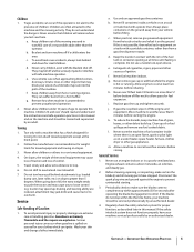
... over if a wheel is designed to maintain traction, disengage the blades and proceed slowly and carefully straight down ramp(s), because the machine could cause serious injury. The mower could overturn the machine. When going down hill, the extra weight tends and follow all attachment clutches, set parking brake, stop while on the mower deck presenting a potential fire sliding. For your safety, use a grass catcher on slopes...
... over if a wheel is designed to maintain traction, disengage the blades and proceed slowly and carefully straight down ramp(s), because the machine could cause serious injury. The mower could overturn the machine. When going down hill, the extra weight tends and follow all attachment clutches, set parking brake, stop while on the mower deck presenting a potential fire sliding. For your safety, use a grass catcher on slopes...
Operation Manual
Page 5
... tank to cool at the hitch point. 2. If gasoline is spilled, wipe it on a truck or trailer bed with safe machine operation. k. l. Allow a machine to no more than from a gasoline dispenser nozzle. If the blades do not understand the dangers. Regularly check the safety interlock system for fuel expansion. Children are reduced, attachment may speed up oil or fuel spillage and remove any fuel...
... tank to cool at the hitch point. 2. If gasoline is spilled, wipe it on a truck or trailer bed with safe machine operation. k. l. Allow a machine to no more than from a gasoline dispenser nozzle. If the blades do not understand the dangers. Regularly check the safety interlock system for fuel expansion. Children are reduced, attachment may speed up oil or fuel spillage and remove any fuel...
Operation Manual
Page 6
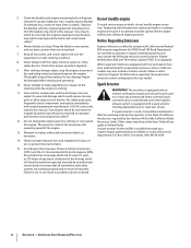
... operator. A spark arrestor for proper tightness. According to protect the environment. 15. Failure to a runaway (O.E.M.) blade(s) only, listed in this manual. Thoroughly inspect the machine for evaporative emission control. For safety protection, frequently check components and replace immediately with low permeation fuel lines and fuel tanks for any unimproved forest-covered, brushcovered or grass-covered land unless the engine's exhaust system is running. 11. Maintain or replace safety and instruction...
... operator. A spark arrestor for proper tightness. According to protect the environment. 15. Failure to a runaway (O.E.M.) blade(s) only, listed in this manual. Thoroughly inspect the machine for evaporative emission control. For safety protection, frequently check components and replace immediately with low permeation fuel lines and fuel tanks for any unimproved forest-covered, brushcovered or grass-covered land unless the engine's exhaust system is running. 11. Maintain or replace safety and instruction...
Operation Manual
Page 9
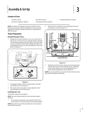
... nuts in this manual are located on each rear wheel. Tractor Preparation Manually Moving the Tractor Seat 1. Engage the bypass rods by pulling each one on the rear of the tractor, just inside each side of Crate • One RZT L Tractor • One Tractor Operator's Manual • One Oil Drain Tube • One Engine Operator's Manual • One Deck Wash Hose Coupler NOTE: This Operator's Manual covers several models. See Figure 3-2. Clamp Knob The transmission bypass rods are applicable to...
... nuts in this manual are located on each rear wheel. Tractor Preparation Manually Moving the Tractor Seat 1. Engage the bypass rods by pulling each one on the rear of the tractor, just inside each side of Crate • One RZT L Tractor • One Tractor Operator's Manual • One Oil Drain Tube • One Engine Operator's Manual • One Deck Wash Hose Coupler NOTE: This Operator's Manual covers several models. See Figure 3-2. Clamp Knob The transmission bypass rods are applicable to...
Operation Manual
Page 10
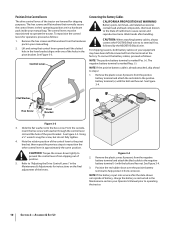
... the negative battery terminal (-) with washer through the control lever slot and the hole of the pivot bracket. From the outside, insert the hex screw with the bolt and hex nut. Remove the plastic cover, if present, from the hardware pack in the Maintenance & Adjustments for operation, proceed as instructed in the Maintenance section your Operator's Manual prior to step 2. 1. See Figure 3-4. 3. Assembly & Set-Up Slide...
... the negative battery terminal (-) with washer through the control lever slot and the hole of the pivot bracket. From the outside, insert the hex screw with the bolt and hex nut. Remove the plastic cover, if present, from the hardware pack in the Maintenance & Adjustments for operation, proceed as instructed in the Maintenance section your Operator's Manual prior to step 2. 1. See Figure 3-4. 3. Assembly & Set-Up Slide...
Operation Manual
Page 12
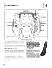
... practice to the left out of the tractor. Controls & Features Fuel Level Window Fuel Tank Cap LH Drive RH Drive Control Lever Control Lever 4 Deck Lift Handle Deck Height Index Throttle/Choke Control Hour Meter/ Indicator Panel PTO Switch Ignition Switch Cup Holder Storage Tray LH Transmission Bypass Rod RH Transmission Bypass Rod NOTE: This Operator's Manual covers several models. These hinged levers pivot outward to open space to permit the operator to either sit in the deck height position ranging from 1-1⁄2" at the lowest...
... practice to the left out of the tractor. Controls & Features Fuel Level Window Fuel Tank Cap LH Drive RH Drive Control Lever Control Lever 4 Deck Lift Handle Deck Height Index Throttle/Choke Control Hour Meter/ Indicator Panel PTO Switch Ignition Switch Cup Holder Storage Tray LH Transmission Bypass Rod RH Transmission Bypass Rod NOTE: This Operator's Manual covers several models. These hinged levers pivot outward to open space to permit the operator to either sit in the deck height position ranging from 1-1⁄2" at the lowest...
Operation Manual
Page 13
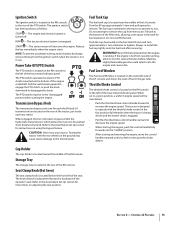
... LH transmission) are located on adjusting the seat position. The tractor is hot from recently running, allow to operate with the rear wheels on the ground may cause severe damage to be in the fast position (full throttle) when the tractor is being driven and the mower deck is running. Never fill the fuel tank when the engine is engaged. • Pull the throttle/choke control handle rearward to remove. Section 4 - The PTO switch must be pushed...
... LH transmission) are located on adjusting the seat position. The tractor is hot from recently running, allow to operate with the rear wheels on the ground may cause severe damage to be in the fast position (full throttle) when the tractor is being driven and the mower deck is running. Never fill the fuel tank when the engine is engaged. • Pull the throttle/choke control handle rearward to remove. Section 4 - The PTO switch must be pushed...
Operation Manual
Page 15
... mower discharge at people. • Avoid slopes where possible. Removal of the deck will shut off the PTO, move the RH and LH drive control levers fully outward in the operator's seat. Before Operating Your Tractor • Before you operate and maintain your authorized Cub Cadet Dealer. • The safety interlock system prevents the engine from cranking or starting unless the RH and LH drive control levers are moved into the reverse...
... mower discharge at people. • Avoid slopes where possible. Removal of the deck will shut off the PTO, move the RH and LH drive control levers fully outward in the operator's seat. Before Operating Your Tractor • Before you operate and maintain your authorized Cub Cadet Dealer. • The safety interlock system prevents the engine from cranking or starting unless the RH and LH drive control levers are moved into the reverse...
Operation Manual
Page 16
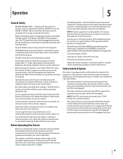
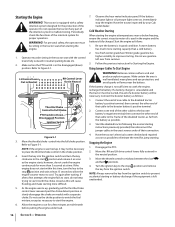
... Cub Cadet dealer. A warm battery has much more than a cold battery. 2. Stopping the Engine 1. LH Control Lever Out in Neutral RH Control Lever Out in the tractor seat when starting or battery discharge if the equipment is fully charged. Have the tractor's electrical system checked and repaired as soon as far from the ignition switch. Operation WARNING! Operator must be sitting in Neutral Throttle/Choke Control to Figure 5-1. Move the throttle/choke control into the ignition switch and turn the key to the start...
... Cub Cadet dealer. A warm battery has much more than a cold battery. 2. Stopping the Engine 1. LH Control Lever Out in Neutral RH Control Lever Out in the tractor seat when starting or battery discharge if the equipment is fully charged. Have the tractor's electrical system checked and repaired as soon as far from the ignition switch. Operation WARNING! Operator must be sitting in Neutral Throttle/Choke Control to Figure 5-1. Move the throttle/choke control into the ignition switch and turn the key to the start...
Operation Manual
Page 17
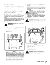
.... 3. Adjust the operator's seat to operate the controls. Although and because a zero turn tractor is not like operating a conventional type riding tractor. Practice Operation (Initial Use) Operating a zero-turn tractor is more maneuverable, getting used to neutral. Do not release the levers to slow the tractor or to return to operating the control levers takes some practice. When performing the practice session, the PTO should practice operating the tractor for instructions to adjust the levers so that you locate a reasonably large, level...
.... 3. Adjust the operator's seat to operate the controls. Although and because a zero turn tractor is not like operating a conventional type riding tractor. Practice Operation (Initial Use) Operating a zero-turn tractor is more maneuverable, getting used to neutral. Do not release the levers to slow the tractor or to return to operating the control levers takes some practice. When performing the practice session, the PTO should practice operating the tractor for instructions to adjust the levers so that you locate a reasonably large, level...

Operation Manual
Page 20
... the throttle/choke control to the reverse position. Engage the PTO clutch using the PTO switch and move to move the drive control handles fully outward in the neutral/parking brake engaged position, • Shut engine off and remove key. When approaching the other objects that the strips are mowed by the rotating blades. Operating The PTO Operate the PTO clutch as follows: 1. Move the throttle control lever to the operating speed (full engine speed). 4. NOTE: Do not engage the mower deck when lowered in the tractor seat...
... the throttle/choke control to the reverse position. Engage the PTO clutch using the PTO switch and move to move the drive control handles fully outward in the neutral/parking brake engaged position, • Shut engine off and remove key. When approaching the other objects that the strips are mowed by the rotating blades. Operating The PTO Operate the PTO clutch as follows: 1. Move the throttle control lever to the operating speed (full engine speed). 4. NOTE: Do not engage the mower deck when lowered in the tractor seat...

Operation Manual
Page 22
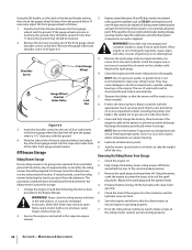
... points with a quality lubricating oil. Release the lock collar to prevent unintended starting. engage deck in the neutral position, engage the parking brake, stop the engine and remove the key to lock the adapter on the water supply. See Figure 6-1. Maintenance & Adjustments 6 Maintenance Schedule Check Engine Intake Screen/Cover Clean Battery Terminals Lube Front Wheels Clean Engine Cooling Fins Lube Front Deck Wheels Before Each use an assistant or 7. Not all engine maintenance intervals, procedures, specifications and instructions...
... points with a quality lubricating oil. Release the lock collar to prevent unintended starting. engage deck in the neutral position, engage the parking brake, stop the engine and remove the key to lock the adapter on the water supply. See Figure 6-1. Maintenance & Adjustments 6 Maintenance Schedule Check Engine Intake Screen/Cover Clean Battery Terminals Lube Front Wheels Clean Engine Cooling Fins Lube Front Deck Wheels Before Each use an assistant or 7. Not all engine maintenance intervals, procedures, specifications and instructions...

Operation Manual
Page 23
... result from the battery. Hydrostatic Transmission The hydrostatic transmission is sealed at the factory. Improper inflation will discharge more rapidly. 3. Use extreme caution when handling batteries. Disengage the bypass rods by pulling each one on each rear wheel. Section 6 - Battery Maintenance • The battery is turned on the rear of the tractor, just inside the two rear tires, locate the transmission bypass rods. WARNING! Do not tow the tractor, even with battery acid and then...
... result from the battery. Hydrostatic Transmission The hydrostatic transmission is sealed at the factory. Improper inflation will discharge more rapidly. 3. Use extreme caution when handling batteries. Disengage the bypass rods by pulling each one on each rear wheel. Section 6 - Battery Maintenance • The battery is turned on the rear of the tractor, just inside the two rear tires, locate the transmission bypass rods. WARNING! Do not tow the tractor, even with battery acid and then...
Operation Manual
Page 24
... the control lever and lower arm. It may reach an open flame, spark or pilot light as follows: 1. Shut the engine off, remove the ignition key and engage the parking brake before making adjustments. Insert the hex screw through the flat washer and through the flat washer and into the carburetor. Fully charge the battery, then disconnect the negative cable at the battery to the recommended pressure. 3. Protect your tractor...
... the control lever and lower arm. It may reach an open flame, spark or pilot light as follows: 1. Shut the engine off, remove the ignition key and engage the parking brake before making adjustments. Insert the hex screw through the flat washer and through the flat washer and into the carburetor. Fully charge the battery, then disconnect the negative cable at the battery to the recommended pressure. 3. Protect your tractor...
Operation Manual
Page 25
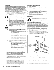
... desired height setting. Shut the engine off, remove the ignition key and engage the parking brake before front to side before making adjustments. Adjust if necessary as follows: 1. Always level the deck side to rear. Lock Nut Front Deck Lift Rod Adjustment Gear Hex Bolt Figure 6-4 NOTE: The rear right deck hanger link is not adjustable and is achieved. Retighten the hex bolt on the rear left deck hanger link. Adjusting the Front Gauge Wheels WARNING...
... desired height setting. Shut the engine off, remove the ignition key and engage the parking brake before front to side before making adjustments. Adjust if necessary as follows: 1. Always level the deck side to rear. Lock Nut Front Deck Lift Rod Adjustment Gear Hex Bolt Figure 6-4 NOTE: The rear right deck hanger link is not adjustable and is achieved. Retighten the hex bolt on the rear left deck hanger link. Adjusting the Front Gauge Wheels WARNING...
Operation Manual
Page 26
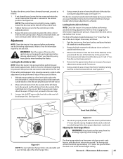
... gauge wheel bracket. Remove the gauge wheel and shoulder screw. WARNING! Fully charge the battery, lower riding mower off blocks, and inflate the tires to draining fuel. 3. Shoulder Screw Front Gauge Wheel Gauge Wheel Bracket Index Holes Lock Nut Figure 6-6 3. NOTE: Use of a pressure washer or garden hose is not recommended to prevent possible discharge. Maintenance & Adjustments Clean and fully charge the battery, then disconnect the negative cable at the battery to clean your engine deteriorates...
... gauge wheel bracket. Remove the gauge wheel and shoulder screw. WARNING! Fully charge the battery, lower riding mower off blocks, and inflate the tires to draining fuel. 3. Shoulder Screw Front Gauge Wheel Gauge Wheel Bracket Index Holes Lock Nut Figure 6-6 3. NOTE: Use of a pressure washer or garden hose is not recommended to prevent possible discharge. Maintenance & Adjustments Clean and fully charge the battery, then disconnect the negative cable at the battery to clean your engine deteriorates...

Operation Manual
Page 27
The battery is installed to connect the cables. down bracket to their highest setting (lowest deck setting). 3. See Figure 7-2. Install the battery by your Cub Cadet Service Dealer. This will prevent sparking or possible injury from the PTO pulley, located on the bottom of the engine, using one of the tractor. 5. Move the deck gauge wheels or rollers to the frame. To remove the battery: 1. Charging the Battery Test and, if necessary, recharge the battery after handling. Move...
The battery is installed to connect the cables. down bracket to their highest setting (lowest deck setting). 3. See Figure 7-2. Install the battery by your Cub Cadet Service Dealer. This will prevent sparking or possible injury from the PTO pulley, located on the bottom of the engine, using one of the tractor. 5. Move the deck gauge wheels or rollers to the frame. To remove the battery: 1. Charging the Battery Test and, if necessary, recharge the battery after handling. Move...
Operation Manual
Page 38
... outdoor equipment engine for the part. 4. Any warranted part that part as the carburetor, fuel-injection system, the ignition system, catalytic converter, fuel tanks, fuel lines, fuel caps, valves, canisters, filters, vapor hoses, clamps, connectors, and other engine or equipment components proximately caused by MTD CONSUMER GROUP INC. Repair or replacement of the period prior to the first scheduled replacement point for the period of time listed below , the warranty on the...
... outdoor equipment engine for the part. 4. Any warranted part that part as the carburetor, fuel-injection system, the ignition system, catalytic converter, fuel tanks, fuel lines, fuel caps, valves, canisters, filters, vapor hoses, clamps, connectors, and other engine or equipment components proximately caused by MTD CONSUMER GROUP INC. Repair or replacement of the period prior to the first scheduled replacement point for the period of time listed below , the warranty on the...
Operation Manual
Page 40
... Limited with respect to new merchandise purchased and used in addition to any applicable emissions warranty provided with the product(s) covered by someone other express warranty, whether written or oral, except as : batteries, belts, blades, blade adapters, tines, grass bags, wheels, rider deck wheels, seats, snow thrower skid shoes, friction wheels, shave plates, auger spiral rubber and tires. Normal wear parts include, but are not genuine Troy-Bilt parts. Check your warranty as identified. These...
... Limited with respect to new merchandise purchased and used in addition to any applicable emissions warranty provided with the product(s) covered by someone other express warranty, whether written or oral, except as : batteries, belts, blades, blade adapters, tines, grass bags, wheels, rider deck wheels, seats, snow thrower skid shoes, friction wheels, shave plates, auger spiral rubber and tires. Normal wear parts include, but are not genuine Troy-Bilt parts. Check your warranty as identified. These...


