
Operation Manual
Page 20
... could overturn and cause serious injury. 1. Using the Mower Deck WARNING! Mow across slopes, never up and down . Do not leave the seat of the 'V" belt and PTO clutch will adversely affect the cut . On the first pass pick a point on a grass surface, always: • Place the control levers in the...
... could overturn and cause serious injury. 1. Using the Mower Deck WARNING! Mow across slopes, never up and down . Do not leave the seat of the 'V" belt and PTO clutch will adversely affect the cut . On the first pass pick a point on a grass surface, always: • Place the control levers in the...

Operation Manual
Page 22
... • Using a pressure lubricating gun, lubricate the front castor wheel axles with a quality lubricating oil. Cleaning the Spindle Pulleys Once a month remove the belt covers to Storing P P P P NOTE: This Operator's Manual covers several models. Clean more often when mowing tall, dry grass. 5. Do not use... P Every 10 Hours P P Every 25 Hours P P Every 50 Hours Every 100 Hours Prior to remove any accumulation of the deck. 22 Pull back the lock collar of the nozzle adapter and push the...
... • Using a pressure lubricating gun, lubricate the front castor wheel axles with a quality lubricating oil. Cleaning the Spindle Pulleys Once a month remove the belt covers to Storing P P P P NOTE: This Operator's Manual covers several models. Clean more often when mowing tall, dry grass. 5. Do not use... P Every 10 Hours P P Every 25 Hours P P Every 50 Hours Every 100 Hours Prior to remove any accumulation of the deck. 22 Pull back the lock collar of the nozzle adapter and push the...
Operation Manual
Page 26
... and allow to idle for storage. Crank the engine one of oil into each cylinder. Allow engine to spread the oil evenly on the drive belts.) 7. Service the engine as STA-BIL® and engines stored over 90 days need to have the carburetor, and other front gauge wheel into anapproved...
... and allow to idle for storage. Crank the engine one of oil into each cylinder. Allow engine to spread the oil evenly on the drive belts.) 7. Service the engine as STA-BIL® and engines stored over 90 days need to have the carburetor, and other front gauge wheel into anapproved...

Operation Manual
Page 27
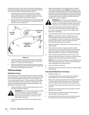
... Remove the hex cap screw and sems nut securing the red positive battery lead to their highest setting (lowest deck setting). 3. Remove the 'V' belt from damage caused by excessive amperage. Charging the Battery Test and, if necessary, recharge the battery after handling. Move the cable away from the tractor...lead to protect the tractor's electrical system from the PTO pulley, located on the bottom of the engine, using one of Charge 100% 75% 50% 25% Charging Time Full Charge 90 Min. 180 Min. 280 Min. WARNING! Move the tractor to free the battery. The muffler at a...
... Remove the hex cap screw and sems nut securing the red positive battery lead to their highest setting (lowest deck setting). 3. Remove the 'V' belt from damage caused by excessive amperage. Charging the Battery Test and, if necessary, recharge the battery after handling. Move the cable away from the tractor...lead to protect the tractor's electrical system from the PTO pulley, located on the bottom of the engine, using one of Charge 100% 75% 50% 25% Charging Time Full Charge 90 Min. 180 Min. 280 Min. WARNING! Move the tractor to free the battery. The muffler at a...

Operation Manual
Page 28
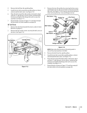
... bottom of the PTO pulley. Refer to avoid pinching your fingers when rolling the belt off the pulley. See Figure 7-3. 28 Section 7- See Figure 7-4. 46/50/54" Decks Moveable Idler Pulley 42" Decks Moveable Idler Pulley PTO Pulley PTO Belt Transmission Tube Fixed Idler Pulley Idler Bracket Idler Bracket Fixed Idler Pulley Figure...
... bottom of the PTO pulley. Refer to avoid pinching your fingers when rolling the belt off the pulley. See Figure 7-3. 28 Section 7- See Figure 7-4. 46/50/54" Decks Moveable Idler Pulley 42" Decks Moveable Idler Pulley PTO Pulley PTO Belt Transmission Tube Fixed Idler Pulley Idler Bracket Idler Bracket Fixed Idler Pulley Figure...

Operation Manual
Page 29
... in the rear hanger bracket slots. 6. Pull the release pins outward and release the deck from beneath the tractor. Make certain the belt is against both the fixed and movable idler pulleys. Deck Lift Arm 10. See Figure 7-5. 12. Service 29 See Figure 7-6. Place the deck lift...pulley on each side of the front hanger bracket. Pull the cotter pin out of the engine. 7. While holding and rotating the pulley and belt until the belt is under each pin fully inward through the lift arms to the deck. Section 7 - Locate the LH and RH deck release pins on...
... in the rear hanger bracket slots. 6. Pull the release pins outward and release the deck from beneath the tractor. Make certain the belt is against both the fixed and movable idler pulleys. Deck Lift Arm 10. See Figure 7-5. 12. Service 29 See Figure 7-6. Place the deck lift...pulley on each side of the front hanger bracket. Pull the cotter pin out of the engine. 7. While holding and rotating the pulley and belt until the belt is under each pin fully inward through the lift arms to the deck. Section 7 - Locate the LH and RH deck release pins on...

Operation Manual
Page 30
... nut. See Figure 7-9. Do not lose any of the hardware when removing the hex screw and flange lock nut. See Figure 7-9. 7. Route the belt as shown and reinstall the belt covers. Remove the deck from beneath the tractor, (refer to secure the assembly. Remove the hex washer screws securing the...lock nuts that secure them to Deck Installation on page 27). 2. Remove the deck from the spindle pulleys. 5. See Figure 7-10. Install the new belt around the idler pulleys removed in step 3 with the "V" side facing in Figure 7-8 and then reinstall the deck (refer to the deck and the idler...
... nut. See Figure 7-9. Do not lose any of the hardware when removing the hex screw and flange lock nut. See Figure 7-9. 7. Route the belt as shown and reinstall the belt covers. Remove the deck from beneath the tractor, (refer to secure the assembly. Remove the hex washer screws securing the...lock nuts that secure them to Deck Installation on page 27). 2. Remove the deck from the spindle pulleys. 5. See Figure 7-10. Install the new belt around the idler pulleys removed in step 3 with the "V" side facing in Figure 7-8 and then reinstall the deck (refer to the deck and the idler...
Operation Manual
Page 31
... Once in place, reinstall all the hardware and tighten the flange lock nut to secure the assembly. See Figure 7-13. 7. Install the new belt around the idler pulleys removed in step 3 with the "V" side facing in Figure 7-11 and then reinstall the deck (refer to Deck Installation on... page 29). 50" & 54" Deck 1. Once in place, reinstall all the hardware and tighten the flange lock nut to secure the assembly. Place the belt around the spindle pulleys as shown and reinstall the belt covers. Remove the deck from the spindle pulleys. ...
... Once in place, reinstall all the hardware and tighten the flange lock nut to secure the assembly. See Figure 7-13. 7. Install the new belt around the idler pulleys removed in step 3 with the "V" side facing in Figure 7-11 and then reinstall the deck (refer to Deck Installation on... page 29). 50" & 54" Deck 1. Once in place, reinstall all the hardware and tighten the flange lock nut to secure the assembly. Place the belt around the spindle pulleys as shown and reinstall the belt covers. Remove the deck from the spindle pulleys. ...
Operation Manual
Page 32
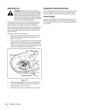
... at all times. Hex Flange Nut Wood Block Spindle Assembly Figure 7-14 3. Tighten the blade nuts to have the transmission drive belt replaced. Sharpen the cutting edges of the blades evenly so that new blades be kept sharp at your Cub Cadet dealer to 70...-90 ft. Reinstall the deck (refer to help in the neutral position. Changing the Transmission Drive Belt Several components must be installed. Tractor Creeping Creeping is maintained. When servicing the mower deck, be removed as follows. 1. Service Before performing...
... at all times. Hex Flange Nut Wood Block Spindle Assembly Figure 7-14 3. Tighten the blade nuts to have the transmission drive belt replaced. Sharpen the cutting edges of the blades evenly so that new blades be kept sharp at your Cub Cadet dealer to 70...-90 ft. Reinstall the deck (refer to help in the neutral position. Changing the Transmission Drive Belt Several components must be installed. Tractor Creeping Creeping is maintained. When servicing the mower deck, be removed as follows. 1. Service Before performing...

Operation Manual
Page 34
....com. 34 Replacement Parts Component 9 Part Number and Description 954-04033A 954-04325 954-05008 954-04329 Deck Belt, RZT L42 Deck Belt, RZT L46 Deck Belt, RZT L50 Deck Belt, RZT L54 954-04317 Drive Belt 942-04312 942-04244A 942-04053C 942-04053C-X 942-0677B 942-0677-X Deck Blade, RZT L42 Deck Blade...
....com. 34 Replacement Parts Component 9 Part Number and Description 954-04033A 954-04325 954-05008 954-04329 Deck Belt, RZT L42 Deck Belt, RZT L46 Deck Belt, RZT L50 Deck Belt, RZT L54 954-04317 Drive Belt 942-04312 942-04244A 942-04053C 942-04053C-X 942-0677B 942-0677-X Deck Blade, RZT L42 Deck Blade...
Operation Manual
Page 40
...belts, blades, blade adapters, tines, grass bags, wheels, rider deck wheels, seats, snow thrower skid shoes, friction wheels, shave plates, auger spiral rubber and tires. No other peril or natural disaster. You assume the risk and liability for loss, damage, or injury to our Web site at P.O. Troy-Bilt...sold or exported outside of the United States and/or Canada, and their respective possessions and territories, except those sold . Troy-Bilt warrants attachments for this product has been operated and maintained in accordance with the Operator's Manual furnished with respect to new ...
...belts, blades, blade adapters, tines, grass bags, wheels, rider deck wheels, seats, snow thrower skid shoes, friction wheels, shave plates, auger spiral rubber and tires. No other peril or natural disaster. You assume the risk and liability for loss, damage, or injury to our Web site at P.O. Troy-Bilt...sold or exported outside of the United States and/or Canada, and their respective possessions and territories, except those sold . Troy-Bilt warrants attachments for this product has been operated and maintained in accordance with the Operator's Manual furnished with respect to new ...

Parts Manual
Page 11
... 2 in 1, 17.9 Lg 34 747-1116 Rod, Deck Hanger 35 754-04044A Belt V, Type A Sec x 134 36 756-04129 Pulley, Idler, 4.25 Dia 37 783-04399 Cover, Belt LH 38 783-04400 Cover, Belt RH 39 783-04414 Skirt, Center 40 783-04415 Skirt, RH 41 783-05030 ...20 x .5 11 710-0726 Screw, Hex Wash. No Description 23 732-0306A Spring, Compression 24 732-0459 Spring, Extension, .94 Dia. TroyBilt Mustang 50" RZT 11 Mower Deck Ref. Hd. Hd. No Description 1 603-04328A Housing, Deck 777S32598 Graphic, Danger 777S30503 Graphic, Danger 777I22282 Graphic, Instruction 777D11833 ...
... 2 in 1, 17.9 Lg 34 747-1116 Rod, Deck Hanger 35 754-04044A Belt V, Type A Sec x 134 36 756-04129 Pulley, Idler, 4.25 Dia 37 783-04399 Cover, Belt LH 38 783-04400 Cover, Belt RH 39 783-04414 Skirt, Center 40 783-04415 Skirt, RH 41 783-05030 ...20 x .5 11 710-0726 Screw, Hex Wash. No Description 23 732-0306A Spring, Compression 24 732-0459 Spring, Extension, .94 Dia. TroyBilt Mustang 50" RZT 11 Mower Deck Ref. Hd. Hd. No Description 1 603-04328A Housing, Deck 777S32598 Graphic, Danger 777S30503 Graphic, Danger 777I22282 Graphic, Instruction 777D11833 ...

Parts Manual
Page 14
... Washer, Flat, .39 x 1.5 .134 13 738-04192 Rod, .405 x 14.0 14 747-04217C Rod, Bypass 15 750-04561 Tube, .45 x .69 x 10.2 16 754-04043 V-Belt, Type A Sec x 57.7 No. Part No. Description No. 1 618-04317 Hub, Wheel 710-0852 Stud, Rib Neck, 7/16-14 x 1.6 2 618-04431A Transmission Assembly, LH 3 618...-18 x 2.25 GR5 5 710-0176 Screw, Hex Cap, 5/16-18 x 2.75 GR5 7 710-3119 Screw, Hex Cap Lock, 3/8-16 x .75 GR5 Ref. Part No. TroyBilt Mustang 50" RZT 14 Hydro Transmissions & Rear Wheels 8 7 12 10 4 1 8 8 16 2 14 13 4 5 15 6 31 9 11 56 10 7 12 Ref.
... Washer, Flat, .39 x 1.5 .134 13 738-04192 Rod, .405 x 14.0 14 747-04217C Rod, Bypass 15 750-04561 Tube, .45 x .69 x 10.2 16 754-04043 V-Belt, Type A Sec x 57.7 No. Part No. Description No. 1 618-04317 Hub, Wheel 710-0852 Stud, Rib Neck, 7/16-14 x 1.6 2 618-04431A Transmission Assembly, LH 3 618...-18 x 2.25 GR5 5 710-0176 Screw, Hex Cap, 5/16-18 x 2.75 GR5 7 710-3119 Screw, Hex Cap Lock, 3/8-16 x .75 GR5 Ref. Part No. TroyBilt Mustang 50" RZT 14 Hydro Transmissions & Rear Wheels 8 7 12 10 4 1 8 8 16 2 14 13 4 5 15 6 31 9 11 56 10 7 12 Ref.


