
Operation Manual
Page 22
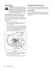
... Nozzle Adapter Adapter Lock Collar Pull Lock Collar Back Deck Wash Nozzle Figure 6-1 Turn on the nozzle. Maintenance WARNING! Cleaning the Spindle Pulleys Once a month remove the belt covers to remove any accumulation of grass clippings from any position other than the operator's seat...'s Manual covers several models. Disengage the PTO and stop the engine. Tractor 3. Do not use P Every 10 Hours P P Every 25 Hours P P Every 50 Hours Every 100 Hours Prior to clean the deck using the deck wash system, never 6. Not all features in the neutral position, engage the parking...
... Nozzle Adapter Adapter Lock Collar Pull Lock Collar Back Deck Wash Nozzle Figure 6-1 Turn on the nozzle. Maintenance WARNING! Cleaning the Spindle Pulleys Once a month remove the belt covers to remove any accumulation of grass clippings from any position other than the operator's seat...'s Manual covers several models. Disengage the PTO and stop the engine. Tractor 3. Do not use P Every 10 Hours P P Every 25 Hours P P Every 50 Hours Every 100 Hours Prior to clean the deck using the deck wash system, never 6. Not all features in the neutral position, engage the parking...
Operation Manual
Page 24
Never store the tractor with fuel in the tank indoors or in poorly ventilated enclosures, where fuel fumes may cause damage to electrical components, spindles, pulleys, bearings or the engine. c. Fully charge the battery, then disconnect the negative cable at the battery to the recommended pressure. 3. NOTE: Remove the battery ...
Never store the tractor with fuel in the tank indoors or in poorly ventilated enclosures, where fuel fumes may cause damage to electrical components, spindles, pulleys, bearings or the engine. c. Fully charge the battery, then disconnect the negative cable at the battery to the recommended pressure. 3. NOTE: Remove the battery ...
Operation Manual
Page 26
... cause damage to protect it on the drive belts.) 7. See Figure 6-6. WARNING! If stored outside, cover the riding mower (including the tires) to electrical components, spindles, pulleys, bearings or the engine. Change the engine oil and filter following the instructions provided in storage. Engines stored between the front gauge wheels and...
... cause damage to protect it on the drive belts.) 7. See Figure 6-6. WARNING! If stored outside, cover the riding mower (including the tires) to electrical components, spindles, pulleys, bearings or the engine. Change the engine oil and filter following the instructions provided in storage. Engines stored between the front gauge wheels and...

Operation Manual
Page 29
... fully inward through the lift arms to place a small block of wood under the tractor on the right side of the belt is in the spindle pulleys on the deck; Using the deck lift handle, raise the deck to grasp the belt and pull it Deck Installation to the left (See... tractor Figure 7-6 frame, above the transmission tube(s), to the PTO pulley on the tractor as necessary to Figure 7-7. 5. Make certain the belt is in the spindle pulleys of the deck, and that the belt has been routed properly. 8. Place the deck lift handle into the PTO pulley. Sitting behind the tractor...
... fully inward through the lift arms to place a small block of wood under the tractor on the right side of the belt is in the spindle pulleys on the deck; Using the deck lift handle, raise the deck to grasp the belt and pull it Deck Installation to the left (See... tractor Figure 7-6 frame, above the transmission tube(s), to the PTO pulley on the tractor as necessary to Figure 7-7. 5. Make certain the belt is in the spindle pulleys of the deck, and that the belt has been routed properly. 8. Place the deck lift handle into the PTO pulley. Sitting behind the tractor...

Operation Manual
Page 30
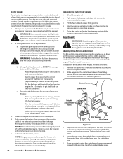
...See Figure 7-9. 7. Do not lose any of the hardware when removing the hex screw and flange lock nut. Hex Washer Screws Belt Cover Spindle Pulley Belt Guard Spindle Pulley Idler Pulley Idler Arm Idler Pulley PTO Pulley Figure 7-10 3. Remove the belt from beneath the tractor, (refer to the deck ...Remove the two idler pulleys by removing the hex screws and flange lock nuts that secure them to the deck. Remove the deck from the spindle pulleys. 5. Remove the two idler pulleys by removing the hex screws and flange lock nuts that secure them to Deck Removal on page 27...
...See Figure 7-9. 7. Do not lose any of the hardware when removing the hex screw and flange lock nut. Hex Washer Screws Belt Cover Spindle Pulley Belt Guard Spindle Pulley Idler Pulley Idler Arm Idler Pulley PTO Pulley Figure 7-10 3. Remove the belt from beneath the tractor, (refer to the deck ...Remove the two idler pulleys by removing the hex screws and flange lock nuts that secure them to the deck. Remove the deck from the spindle pulleys. 5. Remove the two idler pulleys by removing the hex screws and flange lock nuts that secure them to Deck Removal on page 27...
Operation Manual
Page 31
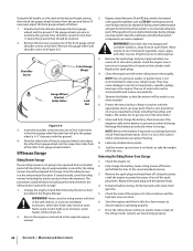
...all the hardware and tighten the flange lock nut to Deck Installation on page 29). Route the belt as shown in . Hex Washer Screws Spindle Pulley Belt Cover 3. Hex Screw Pulley Cap Hex Screw Idler Pulley Idler Pulley Spacer Belt Guard Belt Guard Flange Lock Nut Idler Arm Flange...step 3 with the "V" side facing in Figure 7-11 and then reinstall the deck (refer to Deck Removal on page 29). 50" & 54" Deck 1. Remove the deck from the spindle pulleys. 5. See Figure 7-12. Remove the two idler pulleys by removing the hex screws and flange lock nuts that secure ...
...all the hardware and tighten the flange lock nut to Deck Installation on page 29). Route the belt as shown in . Hex Washer Screws Spindle Pulley Belt Cover 3. Hex Screw Pulley Cap Hex Screw Idler Pulley Idler Pulley Spacer Belt Guard Belt Guard Flange Lock Nut Idler Arm Flange...step 3 with the "V" side facing in Figure 7-11 and then reinstall the deck (refer to Deck Removal on page 29). 50" & 54" Deck 1. Remove the deck from the spindle pulleys. 5. See Figure 7-12. Remove the two idler pulleys by removing the hex screws and flange lock nuts that secure ...
Operation Manual
Page 32
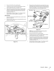
... slight forward or backward movement of the deck. 4. New blades are in breaking loose the hex nut securing the blade. Hex Flange Nut Wood Block Spindle Assembly Figure 7-14 3. lbs. 5. When servicing the mower deck, be removed and special tools used in the "OFF" position, engage the parking ...present, it is recommended that new blades be sure they are installed so that the blades remain balanced and the same angle of the spindle assembly when loosening the hex nut securing the blade. The cutting blades must be careful not to help in the neutral position. Tractor ...
... slight forward or backward movement of the deck. 4. New blades are in breaking loose the hex nut securing the blade. Hex Flange Nut Wood Block Spindle Assembly Figure 7-14 3. lbs. 5. When servicing the mower deck, be removed and special tools used in the "OFF" position, engage the parking ...present, it is recommended that new blades be sure they are installed so that the blades remain balanced and the same angle of the spindle assembly when loosening the hex nut securing the blade. The cutting blades must be careful not to help in the neutral position. Tractor ...

Operation Manual
Page 33
... blade loose or unbalanced. 2. Uneven tire pressure. 1. Perform side-to-side deck adjustment. 2. Wet grass. 3. Dull blade. 8 Remedy 1. Deck not leveled properly. 2. Tighten blade and spindle. 2.
... blade loose or unbalanced. 2. Uneven tire pressure. 1. Perform side-to-side deck adjustment. 2. Wet grass. 3. Dull blade. 8 Remedy 1. Deck not leveled properly. 2. Tighten blade and spindle. 2.

Operation Manual
Page 34
... L50 Extreme Blade, RZT L50 Deck Blade, RZT L54 Extreme Blade, RZT L54 918-04822A 918-05078 918-04125B 918-05137 Deck Spindle, RZT L42 Deck Blade, RZT L46 Deck Spindle, RZT L50 Deck Blade, RZT L54 734-04155 Deck Wheel 925-1707D Battery 951-12428 Fuel Tank Cap Phone (800) 828...
... L50 Extreme Blade, RZT L50 Deck Blade, RZT L54 Extreme Blade, RZT L54 918-04822A 918-05078 918-04125B 918-05137 Deck Spindle, RZT L42 Deck Blade, RZT L46 Deck Spindle, RZT L50 Deck Blade, RZT L54 734-04155 Deck Wheel 925-1707D Battery 951-12428 Fuel Tank Cap Phone (800) 828...

Parts Manual
Page 11
...Wash. Part No. No Description 1 603-04328A Housing, Deck 777S32598 Graphic, Danger 777S30503 Graphic, Danger 777I22282 Graphic, Instruction 777D11833 Graphic, 50" 2 618-04125A Spindle Assembly 3 631-04070A Chute Assembly, Discharge 777S30284 Graphic, Danger 4 683-0254 Bracket, Deck Hanger 5 703-05825B Arm, Idler 6 703... x 1.50 x .12 45 738-1010A Shaft, Spindle, 5.75 46 741-0919 Bearing, Ball 47 748-0160A Spacer, .79 x 1.25 x .175 48 750-1000 Spacer, .80 x 1.10 x 1.32 49 750-1349A Spacer, .79 x 1.82 x .55 50 756-04216 Pulley, V Type, 5.39 Hd. TroyBilt Mustang 50" RZT ...
...Wash. Part No. No Description 1 603-04328A Housing, Deck 777S32598 Graphic, Danger 777S30503 Graphic, Danger 777I22282 Graphic, Instruction 777D11833 Graphic, 50" 2 618-04125A Spindle Assembly 3 631-04070A Chute Assembly, Discharge 777S30284 Graphic, Danger 4 683-0254 Bracket, Deck Hanger 5 703-05825B Arm, Idler 6 703... x 1.50 x .12 45 738-1010A Shaft, Spindle, 5.75 46 741-0919 Bearing, Ball 47 748-0160A Spacer, .79 x 1.25 x .175 48 750-1000 Spacer, .80 x 1.10 x 1.32 49 750-1349A Spacer, .79 x 1.82 x .55 50 756-04216 Pulley, V Type, 5.39 Hd. TroyBilt Mustang 50" RZT ...