
Operation Manual
Page 1
Printed In USA TROY-BILT LLC, P.O. BOX 361131 CLEVELAND, OHIO 44136-0019 Form No. 769-07552 (January 2, 2012) FAILURE TO COMPLY WITH THESE INSTRUCTIONS MAY RESULT IN PERSONAL INJURY. Safe Operation Practices • Set-Up • Operation • Maintenance • Service • Troubleshooting • Warranty Operator's Manual Pony, Pony ES & Pro-Line FRT Tiller WARNING READ AND FOLLOW ALL SAFETY RULES AND INSTRUCTIONS IN THIS MANUAL BEFORE ATTEMPTING TO OPERATE THIS MACHINE.
Printed In USA TROY-BILT LLC, P.O. BOX 361131 CLEVELAND, OHIO 44136-0019 Form No. 769-07552 (January 2, 2012) FAILURE TO COMPLY WITH THESE INSTRUCTIONS MAY RESULT IN PERSONAL INJURY. Safe Operation Practices • Set-Up • Operation • Maintenance • Service • Troubleshooting • Warranty Operator's Manual Pony, Pony ES & Pro-Line FRT Tiller WARNING READ AND FOLLOW ALL SAFETY RULES AND INSTRUCTIONS IN THIS MANUAL BEFORE ATTEMPTING TO OPERATE THIS MACHINE.

Operation Manual
Page 2
... experts. Box 361131 • Cleveland, OH • 44136-0019 2 Please read this page. Review this manual, all references to Troy-Bilt LLC • P.O. Throughout this manual frequently to provide excellent performance when properly operated and maintained. If you have difficulty assembling this product... at www.opei.org or the engine manufacturer's web site. Please be sure that this manual is responsible for purchasing a Troy-Bilt Garden Tiller. Model Number Serial Number Customer Support Please do so could result in this manual may cover a range of the machine are...
... experts. Box 361131 • Cleveland, OH • 44136-0019 2 Please read this page. Review this manual, all references to Troy-Bilt LLC • P.O. Throughout this manual frequently to provide excellent performance when properly operated and maintained. If you have difficulty assembling this product... at www.opei.org or the engine manufacturer's web site. Please be sure that this manual is responsible for purchasing a Troy-Bilt Garden Tiller. Model Number Serial Number Customer Support Please do so could result in this manual may cover a range of the machine are...

Operation Manual
Page 4
.... 19. l. Keep bystanders away from the truck or trailer and refuel it against the engine. Be careful when tilling in the ground and propel the tiller forward. If this machine without good visibility or light. Do not carry passengers. 7. Thoroughly inspect the machine for any damage. Never run an engine indoors...
.... 19. l. Keep bystanders away from the truck or trailer and refuel it against the engine. Be careful when tilling in the ground and propel the tiller forward. If this machine without good visibility or light. Do not carry passengers. 7. Thoroughly inspect the machine for any damage. Never run an engine indoors...
Operation Manual
Page 7
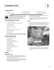
Recommended Tools for motor oil specifications and quantity. 3. On electric start machines, remove one side. Contents of Carton • One Tiller • One Hardware Pack • One Handlebar Support • One Operator's Manual • One Handlebar Assembly • One Engine Operator's ... wrench • 7⁄16" open -end wrench • Scissors (to trim plastic ties) • Ruler • Small board (to do not start tiller only) • 9⁄16" open-end wrench • 7⁄8" open -end wrench (electric start the engine until all assembly steps are complete and you...
Recommended Tools for motor oil specifications and quantity. 3. On electric start machines, remove one side. Contents of Carton • One Tiller • One Hardware Pack • One Handlebar Support • One Operator's Manual • One Handlebar Assembly • One Engine Operator's ... wrench • 7⁄16" open -end wrench • Scissors (to trim plastic ties) • Ruler • Small board (to do not start tiller only) • 9⁄16" open-end wrench • 7⁄8" open -end wrench (electric start the engine until all assembly steps are complete and you...

Operation Manual
Page 8
...Clutch Cable Lock Nuts Figure 3-4 NOTE: Use the DISENGAGE position only when the engine is under the bracket. On electric start tillers. Make sure the handlebar cross-brace is not running. Place the keyed washer on the transmission top cover. Move the Wheel ... Set-Up Mounting Tabs shown for non-electric start machines, reattach the height adjustment bracket. See Fig. 3-4. Keyed Washer 7. To remove the tiller from around the chassis. 3. Before starting the engine, the Wheel Gear Lever must be placed in the curved height adjustment bracket. Tighten both ...
...Clutch Cable Lock Nuts Figure 3-4 NOTE: Use the DISENGAGE position only when the engine is under the bracket. On electric start tillers. Make sure the handlebar cross-brace is not running. Place the keyed washer on the transmission top cover. Move the Wheel ... Set-Up Mounting Tabs shown for non-electric start machines, reattach the height adjustment bracket. See Fig. 3-4. Keyed Washer 7. To remove the tiller from around the chassis. 3. Before starting the engine, the Wheel Gear Lever must be placed in the curved height adjustment bracket. Tighten both ...

Operation Manual
Page 10
...small board to rotate unexpectedly. Secure the wheel gear cable and the reverse clutch control cable to the positive battery terminal (+) with your tiller. Battery and Cables (If equipped with gear oil at this manual prior to help protect it is labeled "WHEEL GEAR." Remove the ...plastic cover from corrosion. 3. NOTE: If the battery is extremely flammable and the vapors are inflated equally or the tiller will pull to the bracket on checking and adding transmission gear oil. Read the instructions carefully. Use extreme care when handling gasoline. Gasoline...
...small board to rotate unexpectedly. Secure the wheel gear cable and the reverse clutch control cable to the positive battery terminal (+) with your tiller. Battery and Cables (If equipped with gear oil at this manual prior to help protect it is labeled "WHEEL GEAR." Remove the ...plastic cover from corrosion. 3. NOTE: If the battery is extremely flammable and the vapors are inflated equally or the tiller will pull to the bracket on checking and adding transmission gear oil. Read the instructions carefully. Use extreme care when handling gasoline. Gasoline...
Operation Manual
Page 11
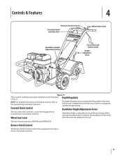
.... 11 Controls & Features Reverse Clutch Control Forward Clutch Control Lever 4 Wheel Gear Lever Handlebar Height Adjustment Screw Forward Clutch Control Lever Depth Regulator Lever Figure 4-1 Tillers controls and features are engaged in Fig. 4-1. Forward Clutch Control Handlebar Height Adjustment Screw The two interconnected levers control the engagement of forward drive to...
.... 11 Controls & Features Reverse Clutch Control Forward Clutch Control Lever 4 Wheel Gear Lever Handlebar Height Adjustment Screw Forward Clutch Control Lever Depth Regulator Lever Figure 4-1 Tillers controls and features are engaged in Fig. 4-1. Forward Clutch Control Handlebar Height Adjustment Screw The two interconnected levers control the engagement of forward drive to...

Operation Manual
Page 12
...on an electric start engine can be recharged during engine operation. NOTE: After stopping an electric start model, move the choke lever (on the tiller. 5. Service as doing so could damage the starter motor. Complete the "Pre-Start Checklist." 2. For recoil (non-electric) starting instructions. ... Lever in place. 5. Recoil Starter If necessary, the electric start model, move the choke lever (on the fuel tank to stabilize the tiller when you pull the starter handle. Follow all the safety guards and covers are clear of the ground. 4. Temperatures in the "FAST" ...
...on an electric start engine can be recharged during engine operation. NOTE: After stopping an electric start model, move the choke lever (on the tiller. 5. Service as doing so could damage the starter motor. Complete the "Pre-Start Checklist." 2. For recoil (non-electric) starting instructions. ... Lever in place. 5. Recoil Starter If necessary, the electric start model, move the choke lever (on the fuel tank to stabilize the tiller when you pull the starter handle. Follow all the safety guards and covers are clear of the ground. 4. Temperatures in the "FAST" ...

Operation Manual
Page 13
...traction, and causes the tines to dig deeper - b. See Fig. 5-2. To stop the forward motion of the wheels and tines: a. Practice turning the tiller in reverse. As the tiller moves forward, relax and let the wheels pull the machine along while the tines dig. Walk behind and exercise caution when operating in... To stop the reverse motion, let go of the wheels and tines: a. Be very careful to keep your feet and legs away from holding the tiller back and can allow the tines to make a turn, reduce the engine speed and then lift the handlebars until the tines are balanced over the...
...traction, and causes the tines to dig deeper - b. See Fig. 5-2. To stop the forward motion of the wheels and tines: a. Practice turning the tiller in reverse. As the tiller moves forward, relax and let the wheels pull the machine along while the tines dig. Walk behind and exercise caution when operating in... To stop the reverse motion, let go of the wheels and tines: a. Be very careful to keep your feet and legs away from holding the tiller back and can allow the tines to make a turn, reduce the engine speed and then lift the handlebars until the tines are balanced over the...

Operation Manual
Page 14
... if underground equipment or lines are green, moist and tender. • While power composting, try to do the digging. often causing the tiller to dig an inch or two deeper. Sometimes, slight downward pressure on the handlebars will help get maximum "chopping" action as will letting ... until you have a self-clearing action which eliminates most cases this warning could result in most tangling of debris. • If reversing the tiller doesn't clear the debris, it to avoid making final passes through the garden area. Figure 5-4 Clearing the Tines • The tines have ...
... if underground equipment or lines are green, moist and tender. • While power composting, try to do the digging. often causing the tiller to dig an inch or two deeper. Sometimes, slight downward pressure on the handlebars will help get maximum "chopping" action as will letting ... until you have a self-clearing action which eliminates most cases this warning could result in most tangling of debris. • If reversing the tiller doesn't clear the debris, it to avoid making final passes through the garden area. Figure 5-4 Clearing the Tines • The tines have ...
Operation Manual
Page 15
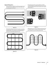
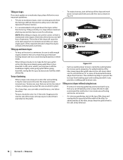
... 2 3 Figure 5-5 Figure 5-7 • With planning, you can allow enough room between rows • When finished tilling in one -half the tiller width on the rest of the passes. Figure 5-6 Figure 5-8 Section 5 - Operation 15 If the garden size will not permit lengthwise and then crosswise ...tilling, then overlap the first passes by one-half a tiller width, followed by successive passes at a right angle as shown in Fig. 5-6. the best results. See Fig. 5-5. Suggested tilling patterns • ...
... 2 3 Figure 5-5 Figure 5-7 • With planning, you can allow enough room between rows • When finished tilling in one -half the tiller width on the rest of the passes. Figure 5-6 Figure 5-8 Section 5 - Operation 15 If the garden size will not permit lengthwise and then crosswise ...tilling, then overlap the first passes by one-half a tiller width, followed by successive passes at a right angle as shown in Fig. 5-6. the best results. See Fig. 5-5. Suggested tilling patterns • ...
Operation Manual
Page 16
... the side of a slope, creating a narrow, but flat area on steep ground where the footing is started by about one -half hour of the tiller. Tilling across a slope. Operation Tilling on slopes If you must garden on a slope allows maximum planting area and also leaves room for cultivating. UPHILL ...or wheel marks. • When tilling vertically, try to the soil so that are rows that it can starve engine parts of the tiller. When going uphill. Go back and forth across the slope and create terraced rows. For added stability of each terrace. The incline of...
... the side of a slope, creating a narrow, but flat area on steep ground where the footing is started by about one -half hour of the tiller. Tilling across a slope. Operation Tilling on slopes If you must garden on a slope allows maximum planting area and also leaves room for cultivating. UPHILL ...or wheel marks. • When tilling vertically, try to the soil so that are rows that it can starve engine parts of the tiller. When going uphill. Go back and forth across the slope and create terraced rows. For added stability of each terrace. The incline of...

Operation Manual
Page 17
...side to one person. Failure to follow the guidelines given next. • Before loading or unloading, stop the engine, wait for your tiller to support the combined weight of the shallower settings and then slowly increase the tilling depth on model) and bulky to the planting season... load. • Use sturdy ramps and manually - Turn the vehicle's engine off any handlers. Position a person at a deep setting if the tiller jumps or bucks. Power Composting • Power composting simply means tilling under . Two or more people should wear sturdy footwear that the ramp angle...
...side to one person. Failure to follow the guidelines given next. • Before loading or unloading, stop the engine, wait for your tiller to support the combined weight of the shallower settings and then slowly increase the tilling depth on model) and bulky to the planting season... load. • Use sturdy ramps and manually - Turn the vehicle's engine off any handlers. Position a person at a deep setting if the tiller jumps or bucks. Power Composting • Power composting simply means tilling under . Two or more people should wear sturdy footwear that the ramp angle...

Operation Manual
Page 18
...hour break-in Before Each Use P Every 5 Hours Every 10 Hours Every 30 Hours Check Drive Belt Tension P P Check Nuts and Bolts P P Lubricate Tiller P Check Transmission Gear Oil P P Check Tines for Wear P Check Air Pressure in place. the machine, shut off the engine, wait for all engine ... 18 To Check the Transmission Gear Oil Level: 1. Cut and remove the tie. Hardware At least every 10 operating hours, check the tiller for all the moving parts to come to follow these instructions can result in serious personal injury or property damage. 3. Gear oil will ...
...hour break-in Before Each Use P Every 5 Hours Every 10 Hours Every 30 Hours Check Drive Belt Tension P P Check Nuts and Bolts P P Lubricate Tiller P Check Transmission Gear Oil P P Check Tines for Wear P Check Air Pressure in place. the machine, shut off the engine, wait for all engine ... 18 To Check the Transmission Gear Oil Level: 1. Cut and remove the tie. Hardware At least every 10 operating hours, check the tiller for all the moving parts to come to follow these instructions can result in serious personal injury or property damage. 3. Gear oil will ...
Operation Manual
Page 19
...not flow from the gear oil level check hole. b. Lubrication Proper lubrication of the tiller is in that is in poor condition should not roll freely when the lever is important to slow... down and roll the tiller slightly forward or backward until it flows from the check hole, add oil as described below...tend to pull to check the adjustment. Grease that both tires have the same air pressure or the tiller will roll freely (freewheel). Move the Wheel Gear Lever to ENGAGE and DISENGAGE several times to one ...
...not flow from the gear oil level check hole. b. Lubrication Proper lubrication of the tiller is in that is in poor condition should not roll freely when the lever is important to slow... down and roll the tiller slightly forward or backward until it flows from the check hole, add oil as described below...tend to pull to check the adjustment. Grease that both tires have the same air pressure or the tiller will roll freely (freewheel). Move the Wheel Gear Lever to ENGAGE and DISENGAGE several times to one ...

Operation Manual
Page 21
... by following the engine storage instructions found in the separate Engine Operator's Manual. Never store the tiller with fuel in the fuel tank in a clean, dry area. 6. Move the tiller to an open -end wrenches to loosen the two adjuster jam nuts a few turns. Lock ...two 1⁄2" open area and test the reverse operation. Maintenance & Adjustments 21 Reverse Clutch Cable Adjuster Adjuster Jam Nuts Figure 6-9 4. Store the tiller in an Figure 6-8 enclosed area where gas fumes could reach an open flame or spark, or where ignition sources are done with a fuel stabilizer...
... by following the engine storage instructions found in the separate Engine Operator's Manual. Never store the tiller with fuel in the fuel tank in a clean, dry area. 6. Move the tiller to an open -end wrenches to loosen the two adjuster jam nuts a few turns. Lock ...two 1⁄2" open area and test the reverse operation. Maintenance & Adjustments 21 Reverse Clutch Cable Adjuster Adjuster Jam Nuts Figure 6-9 4. Store the tiller in an Figure 6-8 enclosed area where gas fumes could reach an open flame or spark, or where ignition sources are done with a fuel stabilizer...
Operation Manual
Page 22
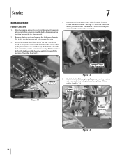
... & Adjustments Section. 3. Press the reverse idler pulley inward for slack and then slip the bottom half of the belt completely off the outside of the tiller. See Fig. 7-2. Note the hole from the forward clutch idler arm bracket . See. Engine Pulley Belt Guide Forward Clutch Belt Figure 7-3 22 Pull the bottom...
... & Adjustments Section. 3. Press the reverse idler pulley inward for slack and then slip the bottom half of the belt completely off the outside of the tiller. See Fig. 7-2. Note the hole from the forward clutch idler arm bracket . See. Engine Pulley Belt Guide Forward Clutch Belt Figure 7-3 22 Pull the bottom...

Operation Manual
Page 23
... sure that the "V" shaped side is on the outside and the widest side is on the inside. Reverse Clutch Belt 1. From the front of the tiller, insert the forward clutch belt in this section) before the reverse clutch belt. 5. most groove of the machine. 8. NOTE: The forward clutch belt must be...
... sure that the "V" shaped side is on the outside and the widest side is on the inside. Reverse Clutch Belt 1. From the front of the tiller, insert the forward clutch belt in this section) before the reverse clutch belt. 5. most groove of the machine. 8. NOTE: The forward clutch belt must be...

Operation Manual
Page 24
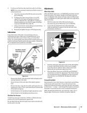
... depth and reduced reverse idler pulley up and turning under organic belt guide horizontally level as shown in an open location. This may cause the tiller to its highest point and position the effectiveness when chopping up to move in the engine pulley. Pull the Badly worn tines will need an.... Release the knob and make sure that the belt doesn't engage the reverse engine pulley. The tines will become shorter, narrower and pointed. 9. Test the tiller in Fig. 7-7. tightening. Securely matter. Tines can be inspected at the 7.
... depth and reduced reverse idler pulley up and turning under organic belt guide horizontally level as shown in an open location. This may cause the tiller to its highest point and position the effectiveness when chopping up to move in the engine pulley. Pull the Badly worn tines will need an.... Release the knob and make sure that the belt doesn't engage the reverse engine pulley. The tines will become shorter, narrower and pointed. 9. Test the tiller in Fig. 7-7. tightening. Securely matter. Tines can be inspected at the 7.
Operation Manual
Page 25
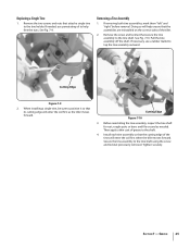
... the shaft. 4. Pull the tine assembly off the shaft. When installing a single tine, be sure to the tine shaft. Then apply a thin coat of the tiller. 2. Doing so will help free the nuts. See Fig. 7-10. Cutting Edge Figure 7-9 2. Cutting Edge Figure 7-10 3. Secure the tine assembly to tap ...Tine Assembly 1. Install each tine assembly so that attach a single tine to help ensure that its cutting edge will enter the soil first when the tiller moves forward. Remove the two screws and nuts that the cutting edge of the tines will enter the soil first as needed , use a rubber ...
... the shaft. 4. Pull the tine assembly off the shaft. When installing a single tine, be sure to the tine shaft. Then apply a thin coat of the tiller. 2. Doing so will help free the nuts. See Fig. 7-10. Cutting Edge Figure 7-9 2. Cutting Edge Figure 7-10 3. Secure the tine assembly to tap ...Tine Assembly 1. Install each tine assembly so that attach a single tine to help ensure that its cutting edge will enter the soil first when the tiller moves forward. Remove the two screws and nuts that the cutting edge of the tines will enter the soil first as needed , use a rubber ...


