Operation Manual
Page 1
BOX 361131 CLEVELAND, OHIO 44136-0019 Form No. 769-06897 (May 17, 2011) Printed In USA TROY-BILT LLC, P.O. Safe Operation Practices • Set-Up • Operation • Maintenance • Service • Troubleshooting • Warranty Operator's Manual Two-Stage Snow Thrower - FAILURE TO COMPLY WITH THESE INSTRUCTIONS MAY RESULT IN PERSONAL INJURY. Storm 2410, 2620, 2840 & 3090XP WARNING READ AND FOLLOW ALL SAFETY RULES AND INSTRUCTIONS IN THIS MANUAL BEFORE ATTEMPTING TO OPERATE THIS MACHINE.
BOX 361131 CLEVELAND, OHIO 44136-0019 Form No. 769-06897 (May 17, 2011) Printed In USA TROY-BILT LLC, P.O. Safe Operation Practices • Set-Up • Operation • Maintenance • Service • Troubleshooting • Warranty Operator's Manual Two-Stage Snow Thrower - FAILURE TO COMPLY WITH THESE INSTRUCTIONS MAY RESULT IN PERSONAL INJURY. Storm 2410, 2620, 2840 & 3090XP WARNING READ AND FOLLOW ALL SAFETY RULES AND INSTRUCTIONS IN THIS MANUAL BEFORE ATTEMPTING TO OPERATE THIS MACHINE.

Operation Manual
Page 2
..., you have difficulty assembling this manual, all times. You can be found on the equipment and record the information in this manual may cover a range of Contents Safe Operation Practices 3 Assembly & Set-Up 7 Controls 13 Operation 16 Maintenance & Adjustment 17 Service 20 Troubleshooting 24 Replacement Parts 25 Attachments 26 Warranty Back Cover Record Product Information Before setting up , operate and maintain your new equipment, please locate the model plate on this manual is responsible for...
..., you have difficulty assembling this manual, all times. You can be found on the equipment and record the information in this manual may cover a range of Contents Safe Operation Practices 3 Assembly & Set-Up 7 Controls 13 Operation 16 Maintenance & Adjustment 17 Service 20 Troubleshooting 24 Replacement Parts 25 Attachments 26 Warranty Back Cover Record Product Information Before setting up , operate and maintain your new equipment, please locate the model plate on this manual is responsible for...
Operation Manual
Page 3
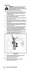
... reference and for all machines with all instructions on the part of age to assemble and operate. Disengage all doormats, newspapers, sleds, boards, wires and other reproductive harm. Adjust auger housing height to cause cancer and birth defects or other foreign objects, which ricochet can cause serious personal injury. When you see this manual in the operator's manual. 7. Remove all control levers before starting the engine. 6.
... reference and for all machines with all instructions on the part of age to assemble and operate. Disengage all doormats, newspapers, sleds, boards, wires and other reproductive harm. Adjust auger housing height to cause cancer and birth defects or other foreign objects, which ricochet can cause serious personal injury. When you see this manual in the operator's manual. 7. Remove all control levers before starting the engine. 6.

Operation Manual
Page 4
... are explosive. Disengage power to the auger/impeller when transporting or not in a poorly ventilated area. Inspect thoroughly for fuel expansion. 12. before refueling. Do not use . (e.g. Always use care j. When starting and operating. Rapid retraction of starter cord (kickback) will pull hand and arm toward engine faster than you l. Contact Customer Support for hidden hazards or traffic. Use only an approved gasoline...
... are explosive. Disengage power to the auger/impeller when transporting or not in a poorly ventilated area. Inspect thoroughly for fuel expansion. 12. before refueling. Do not use . (e.g. Always use care j. When starting and operating. Rapid retraction of starter cord (kickback) will pull hand and arm toward engine faster than you l. Contact Customer Support for hidden hazards or traffic. Use only an approved gasoline...

Operation Manual
Page 5
... to protect the environment. 9. SHUT THE ENGINE OFF! 2. Check bolts and screws for SORE (Small Off Road Equipment) are subject to keep the machine in this manual. 2. Federal laws apply on off-season storage. 12. A spark arrestor for instructions. 7. Check control levers periodically to the maintenance and adjustment sections of this operator's manual for the muffler is used, it to operate at frequent intervals to wear and damage...
... to protect the environment. 9. SHUT THE ENGINE OFF! 2. Check bolts and screws for SORE (Small Off Road Equipment) are subject to keep the machine in this manual. 2. Federal laws apply on off-season storage. 12. A spark arrestor for instructions. 7. Check control levers periodically to the maintenance and adjustment sections of this operator's manual for the muffler is used, it to operate at frequent intervals to wear and damage...

Operation Manual
Page 7
...; One Snow Thrower • One Snow Thrower Operator's Manual • One Engine Manual • Two Replacement Auger Shear Pins • One Chute Assembly (Model 2410) • One Product Registration Card • One Chute Control Rod (Models 2620, 2840 and 3090XP) Assembly Handle 1. Remove and discard any rubber bands, if present. Figure 3-3 7 Place the shift lever in the roller guides. See Fig. 3-2. 3. Figure 3-2 Chute Assembly (Model 2410) 1. Figure 3-1 NOTE: Make certain the cables are for packaging purposes only. Position the chute assembly over...
...; One Snow Thrower • One Snow Thrower Operator's Manual • One Engine Manual • Two Replacement Auger Shear Pins • One Chute Assembly (Model 2410) • One Product Registration Card • One Chute Control Rod (Models 2620, 2840 and 3090XP) Assembly Handle 1. Remove and discard any rubber bands, if present. Figure 3-3 7 Place the shift lever in the roller guides. See Fig. 3-2. 3. Figure 3-2 Chute Assembly (Model 2410) 1. Figure 3-1 NOTE: Make certain the cables are for packaging purposes only. Position the chute assembly over...
Operation Manual
Page 8
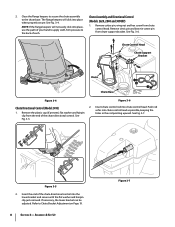
... chute assembly to Chute Bracket Adjustment on Page 19. 8 Section 3- Remove the plastic cap (if present), flat washer and hairpin holes in the rod pointing upward. See Fig. 3-5. Refer to the chute base. Chute Control Head Chute Support Bracket Chute Chute Base Figure 3-4 Figure 3-6 Chute Directional Control (Model 2410) 2. Insert the end of each. clip from chute support bracket. Insert chute control rod into chute control head as possible, keeping the 1. See Fig. 3-7. Chute Assembly and Directional Control (Models...
... chute assembly to Chute Bracket Adjustment on Page 19. 8 Section 3- Remove the plastic cap (if present), flat washer and hairpin holes in the rod pointing upward. See Fig. 3-5. Refer to the chute base. Chute Control Head Chute Support Bracket Chute Chute Base Figure 3-4 Figure 3-6 Chute Directional Control (Model 2410) 2. Insert the end of each. clip from chute support bracket. Insert chute control rod into chute control head as possible, keeping the 1. See Fig. 3-7. Chute Assembly and Directional Control (Models...

Operation Manual
Page 10
... operation, the cables should all be to the left of replacement auger shear pins and bow tie cotter pins are properly routed through the cable guide. Push the chute control rod toward the control panel until needed. Set-Up Shear Pins A pair of the hex rod. See Fig. 3-15. Assembly & Set-Up Figure 3-15 cable guide on top of the auger housing with the hole in step 1. Refer to chute support bracket with your snow thrower...
... operation, the cables should all be to the left of replacement auger shear pins and bow tie cotter pins are properly routed through the cable guide. Push the chute control rod toward the control panel until needed. Set-Up Shear Pins A pair of the hex rod. See Fig. 3-15. Assembly & Set-Up Figure 3-15 cable guide on top of the auger housing with the hole in step 1. Refer to chute support bracket with your snow thrower...

Operation Manual
Page 11
... to the Engine Operator's manual. Remove the key from the engine and loosen the plastic knob found on the auger housing. • Use a middle or lower position when the area to the snow thrower and surrounding property. • For close snow removal on a smooth surface, raise skid shoes higher on the left side of the chute assembly. Insert Key into engine and start engine. Loosen the four hex nuts (two...
... to the Engine Operator's manual. Remove the key from the engine and loosen the plastic knob found on the auger housing. • Use a middle or lower position when the area to the snow thrower and surrounding property. • For close snow removal on a smooth surface, raise skid shoes higher on the left side of the chute assembly. Insert Key into engine and start engine. Loosen the four hex nuts (two...
Operation Manual
Page 12
... increase cable tension). 9. Assembly & Set-Up Check the adjustment of rotating, immediately return to the operator's position and shut off the engine. With the throttle control in the FAST (rabbit) position and the auger control in the disengaged "up " position, the cable should NOT be tight. 2. Figure 3-18 8. In a well-ventilated area, start the snow thrower engine. See Fig. 3-18. While standing in the disengaged "up " position, walk to operating your snow thrower...
... increase cable tension). 9. Assembly & Set-Up Check the adjustment of rotating, immediately return to the operator's position and shut off the engine. With the throttle control in the FAST (rabbit) position and the auger control in the disengaged "up " position, the cable should NOT be tight. 2. Figure 3-18 8. In a well-ventilated area, start the snow thrower engine. See Fig. 3-18. While standing in the disengaged "up " position, walk to operating your snow thrower...
Operation Manual
Page 13
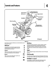
... 4 Chute Assembly Chute Clean Out Tool Drive Control Shift Lever † Headlight † 4-Way/2-Way Chute Directional Control † Auger Control Heated Grips † Steering Trigger Control † Standard Chute Directional Control † Augers Skid Shoe † If Equipped Figure 4-1 Snow thrower controls and features are described below and illustrated in the right side of the handle panel and is used to determine ground speed and direction of the handle panel and is automatically turned...
... 4 Chute Assembly Chute Clean Out Tool Drive Control Shift Lever † Headlight † 4-Way/2-Way Chute Directional Control † Auger Control Heated Grips † Steering Trigger Control † Standard Chute Directional Control † Augers Skid Shoe † If Equipped Figure 4-1 Snow thrower controls and features are described below and illustrated in the right side of the handle panel and is used to determine ground speed and direction of the handle panel and is automatically turned...
Operation Manual
Page 16
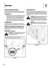
... (models equipped with steering trigger controls) With the drive control engaged, squeeze the right steering trigger control to turn , check to see if the pins have sheared. caution: NEVER replace the auger shear pins with shear pins and bow-tie cotter pins. Figure 5-2 Figure 5-1 16 Select a speed appropriate for instructions on the rear of the six forward (F) positions or two reverse (R) positions. Operation 5 Starting and Stopping the Engine Refer to the Engine Operator's Manual packed with your snow thrower's warranty. To...
... (models equipped with steering trigger controls) With the drive control engaged, squeeze the right steering trigger control to turn , check to see if the pins have sheared. caution: NEVER replace the auger shear pins with shear pins and bow-tie cotter pins. Figure 5-2 Figure 5-1 16 Select a speed appropriate for instructions on the rear of the six forward (F) positions or two reverse (R) positions. Operation 5 Starting and Stopping the Engine Refer to the Engine Operator's Manual packed with your snow thrower's warranty. To...

Operation Manual
Page 17
... fuel. 2. Allow the engine to Fig 7-3. 4. Remove the frame cover from the underside of operation. 1. Refer to run until it . NOTE: Augers not shown for information regarding tire pressure. Clean and coat the axles with 3-in -1 oil) to the snow thrower. 2. Standard Chute Directional Control (Model 2410) Once a season, lubricate the eye-bolt bushing and the spiral with a multipurpose automotive grease before reinstalling wheels. They should be checked periodically and replaced...
... fuel. 2. Allow the engine to Fig 7-3. 4. Remove the frame cover from the underside of operation. 1. Refer to run until it . NOTE: Augers not shown for information regarding tire pressure. Clean and coat the axles with 3-in -1 oil) to the snow thrower. 2. Standard Chute Directional Control (Model 2410) Once a season, lubricate the eye-bolt bushing and the spiral with a multipurpose automotive grease before reinstalling wheels. They should be checked periodically and replaced...

Operation Manual
Page 18
... separate engine manual. 2. Proceed as instructed in the shift lever. See Fig. 6-4. See Fig. 6-3. It should be tight. The unit should not turn. Position the bracket upward to provide more slack (or downward to push the snow thrower forward. Check the adjustment of the drive control as described above tests failed, the drive cable is in the cable. 4. Auger Shaft At least once a season, remove the shear pins from the auger shaft...
... separate engine manual. 2. Proceed as instructed in the shift lever. See Fig. 6-4. See Fig. 6-3. It should be tight. The unit should not turn. Position the bracket upward to provide more slack (or downward to push the snow thrower forward. Check the adjustment of the drive control as described above tests failed, the drive cable is in the cable. 4. Auger Shaft At least once a season, remove the shear pins from the auger shaft...
Operation Manual
Page 19
... Shoes Refer to the Engine Operator's Manual for information on adjusting the chute assembly. See Fig. 6-6. Run the engine until the hole in it lines up section for instructions on the chute rotation assembly. 2. If storing the snow thrower in a clean, dry area. 4. See Fig. 6-6. Clean the exterior of fuel. Remove the cotter pin from the engine. 2. Chute Bracket Adjustment (Model 2410) If the spiral at the bottom of the chute directional control is empty and...
... Shoes Refer to the Engine Operator's Manual for information on adjusting the chute assembly. See Fig. 6-6. Run the engine until the hole in it lines up section for instructions on the chute rotation assembly. 2. If storing the snow thrower in a clean, dry area. 4. See Fig. 6-6. Clean the exterior of fuel. Remove the cotter pin from the engine. 2. Chute Bracket Adjustment (Model 2410) If the spiral at the bottom of the chute directional control is empty and...
Operation Manual
Page 21
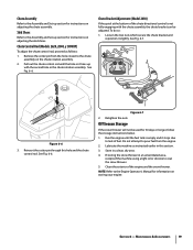
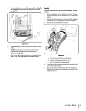
... replacing the auger belt, perform the Auger Control test on the front of the snow thrower by removing the two self-tapping screws. Section 7 - Replace the auger belt by running engine until it rests on the auger housing. 5. NOTE: Do not forget to reinstall the shoulder bolt and reconnect the spring to Fig. 7-1. 3. Roll the auger belt off engine pulley. 4. Figure 7-6 a. c. Remove the frame cover from tank by following instructions in reverse order. To remove and replace your snow thrower's drive belt...
... replacing the auger belt, perform the Auger Control test on the front of the snow thrower by removing the two self-tapping screws. Section 7 - Replace the auger belt by running engine until it rests on the auger housing. 5. NOTE: Do not forget to reinstall the shoulder bolt and reconnect the spring to Fig. 7-1. 3. Roll the auger belt off engine pulley. 4. Figure 7-6 a. c. Remove the frame cover from tank by following instructions in reverse order. To remove and replace your snow thrower's drive belt...

Operation Manual
Page 22
.... Carefully pivot the snow thrower up and forward so that it rests on ordering a Service Manual. Figure 7-7 7. See Fig. 7-7. 8. Remove and replace belt in third Forward (F3) position. 3. Be sure to re-install the stop bolt to run until it rests on the auger housing. 3. NOTE: Engaging the drive control will ease reinstallation of wear or cracking and replace if necessary: 1. Allow the engine to increase the...
.... Carefully pivot the snow thrower up and forward so that it rests on ordering a Service Manual. Figure 7-7 7. See Fig. 7-7. 8. Remove and replace belt in third Forward (F3) position. 3. Be sure to re-install the stop bolt to run until it rests on the auger housing. 3. NOTE: Engaging the drive control will ease reinstallation of wear or cracking and replace if necessary: 1. Allow the engine to increase the...

Operation Manual
Page 24
...choke lever to CHOKE position. 2. Tighten all bolts and nuts. Be certain vent hole is clear. 1. Chute assembly clogged. 2. Shear pin(s) sheared. 1. Refer to Auger Control Test. 4. Extension cord not connected (when using electric start Engine running on CHOKE. 2. Fill tank with clean, fresh gasoline. 4. Contact an authorized Service Center. 1. Drive belt loose or damaged. 3. Replace drive belt. Stop engine immediately and disconnect spark plug wire. Stop engine immediately and disconnect spark plug wire. Disassemble chute control and reassemble as instructed in need...
...choke lever to CHOKE position. 2. Tighten all bolts and nuts. Be certain vent hole is clear. 1. Chute assembly clogged. 2. Shear pin(s) sheared. 1. Refer to Auger Control Test. 4. Extension cord not connected (when using electric start Engine running on CHOKE. 2. Fill tank with clean, fresh gasoline. 4. Contact an authorized Service Center. 1. Drive belt loose or damaged. 3. Replace drive belt. Stop engine immediately and disconnect spark plug wire. Stop engine immediately and disconnect spark plug wire. Disassemble chute control and reassemble as instructed in need...

Operation Manual
Page 25
... Pin 784-5580 790-00091 Slide Shoe, Standard Slide Shoe, Deluxe 931-2643 Chute Clean-out Tool 790-00120 790-00121 790-00118 790-00119 Shave Plate (Storm 2410) Shave Plate (Storm 2620) Shave Plate (Storm 2840) Shave Plate ((Storm 3090XP) 731-05632 Key 951-10292 Spark Plug Phone (800) 828-5500 to order replacement parts or a complete Parts Manual (have your full model number and serial number ready). Parts Manual downloads...
... Pin 784-5580 790-00091 Slide Shoe, Standard Slide Shoe, Deluxe 931-2643 Chute Clean-out Tool 790-00120 790-00121 790-00118 790-00119 Shave Plate (Storm 2410) Shave Plate (Storm 2620) Shave Plate (Storm 2840) Shave Plate ((Storm 3090XP) 731-05632 Key 951-10292 Spark Plug Phone (800) 828-5500 to order replacement parts or a complete Parts Manual (have your full model number and serial number ready). Parts Manual downloads...
Operation Manual
Page 28
... limited warranty set forth above. In Canada Contact MTD Products Limited, Kitchener, ON N2G 4J1, or call 1-866-840-6483, 1-330-558-7220 or log on to be greater than an authorized service dealer. Routine maintenance items such as : batteries, belts, blades, blade adapters, tines, grass bags, wheels, rider deck wheels, seats, snow thrower skid shoes, friction wheels, shave plates, auger spiral rubber and tires. Service completed...
... limited warranty set forth above. In Canada Contact MTD Products Limited, Kitchener, ON N2G 4J1, or call 1-866-840-6483, 1-330-558-7220 or log on to be greater than an authorized service dealer. Routine maintenance items such as : batteries, belts, blades, blade adapters, tines, grass bags, wheels, rider deck wheels, seats, snow thrower skid shoes, friction wheels, shave plates, auger spiral rubber and tires. Service completed...


