

English Owners Manual
Page 9
... MMSI set, the radio displays MMSI not entered. Antenna connector (SO238) Heat sink Accessory cable Red wire (+) ANTENNA 13.8V DC Black wire (-) Power Cable Connector/Cable Antenna connector Power cable Connects to 16.0 VDC) (Red wire +, black wire -). Nominal 13.8 VDC power supply with a male PL259 (SO238) connector and 50 Ω impedance. Connecting...
... MMSI set, the radio displays MMSI not entered. Antenna connector (SO238) Heat sink Accessory cable Red wire (+) ANTENNA 13.8V DC Black wire (-) Power Cable Connector/Cable Antenna connector Power cable Connects to 16.0 VDC) (Red wire +, black wire -). Nominal 13.8 VDC power supply with a male PL259 (SO238) connector and 50 Ω impedance. Connecting...

English Owners Manual
Page 33
... has called. First, determine the best place to hold the radio, depending on the rear of the mounting surface. xx Keep the antenna lead-in wire as short as possible. be able to the mounting surface. special requirements of the radio. xx Avoid interference with the mounting screws to mount the...
... has called. First, determine the best place to hold the radio, depending on the rear of the mounting surface. xx Keep the antenna lead-in wire as short as possible. be able to the mounting surface. special requirements of the radio. xx Avoid interference with the mounting screws to mount the...
English Owners Manual
Page 34
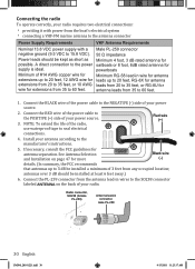
... Power leads should be kept as short as Minimum 4 foot, 3 dB rated antenna for extensions from 35 to 35 feet, or RG-8U for wire for possible. NOTE: To extend the life of your power source. 2. Install your power source. 3. Connecting the radio To operate correctly, your radio... connections: xx providing it with power from any occupied location; Radio connector, SO238 (female PL-259) Antenna lead-in wire for antenna extensions up to 20 feet, 12 AWG wire for leads up to the power sailboats or 8 foot, 6dB rated antenna for antenna separation. Connect the BLACK...
... Power leads should be kept as short as Minimum 4 foot, 3 dB rated antenna for extensions from 35 to 35 feet, or RG-8U for wire for possible. NOTE: To extend the life of your power source. 2. Install your power source. 3. Connecting the radio To operate correctly, your radio... connections: xx providing it with power from any occupied location; Radio connector, SO238 (female PL-259) Antenna lead-in wire for antenna extensions up to 20 feet, 12 AWG wire for leads up to the power sailboats or 8 foot, 6dB rated antenna for antenna separation. Connect the BLACK...

English Owners Manual
Page 35
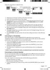
...GPS receiver. Speaker (-)/GND Green: GPS Data IN (+) Red: External Speaker (+) Bare wire: Ground Yellow: NMEA OUT (+) 1. Connect the GREEN wire of the included accessory cable to the GROUND WIRE on your GPS receiver. 2. Follow the steps below to connect your radio to your current...table of common GPS receivers and the proper connections: GPS Manufacturer GPS NMEA0183 Model Number(s) OUTPUT Wire Color (Connect to GREEN WIRE on your radio) Ground Wire Color (connect to BARE WIRE on your radio) Furuno GP1650, GP1850 White Black Furuno GP30, GP36 White Blue Garmin Fixed ...
...GPS receiver. Speaker (-)/GND Green: GPS Data IN (+) Red: External Speaker (+) Bare wire: Ground Yellow: NMEA OUT (+) 1. Connect the GREEN wire of the included accessory cable to the GROUND WIRE on your GPS receiver. 2. Follow the steps below to connect your radio to your current...table of common GPS receivers and the proper connections: GPS Manufacturer GPS NMEA0183 Model Number(s) OUTPUT Wire Color (Connect to GREEN WIRE on your radio) Ground Wire Color (connect to BARE WIRE on your radio) Furuno GP1650, GP1850 White Black Furuno GP30, GP36 White Blue Garmin Fixed ...

English Owners Manual
Page 36
...If the radio is receiving valid GPS data, it transmits valid data, the display shows GPS Data OK. Press ENT-1W25W to open wires are close to the border of the radio, use waterproof tape to seal electrical connections. See page 16 to manually set the clock ... Yellow 3. GPS Verification If the GPS receiver is connected. Be certain all wire connections are updated. GPS Manufacturer Northstar RayMarine RayMarine RayMarine Simrad Sitex Standard GPS NMEA0183 Model Number(s) OUTPUT Wire Color (Connect to GREEN WIRE on your radio) All Models Yellow 420 Yellow 520 / 620 Blue RL ...
...If the radio is receiving valid GPS data, it transmits valid data, the display shows GPS Data OK. Press ENT-1W25W to open wires are close to the border of the radio, use waterproof tape to seal electrical connections. See page 16 to manually set the clock ... Yellow 3. GPS Verification If the GPS receiver is connected. Be certain all wire connections are updated. GPS Manufacturer Northstar RayMarine RayMarine RayMarine Simrad Sitex Standard GPS NMEA0183 Model Number(s) OUTPUT Wire Color (Connect to GREEN WIRE on your radio) All Models Yellow 420 Yellow 520 / 620 Blue RL ...
English Owners Manual
Page 37
... sends the position data to the chartplotter so you to confirm the setting: choose Set to save the new time or Cancel to the NEGATIVE (-) wire of the radio, use CHANNEL DOWN button. Setup Use the up and down arrows to adjust the time by GPS Setup one hour, use waterproof... tape to the POSITIVE (+) wire of your chartplotter's NMEA data INPUT. 2. To adjust the time back one hour. When it will also adjust the external speaker volume. Connect the YELLOW...
... sends the position data to the chartplotter so you to confirm the setting: choose Set to save the new time or Cancel to the NEGATIVE (-) wire of the radio, use CHANNEL DOWN button. Setup Use the up and down arrows to adjust the time by GPS Setup one hour, use waterproof... tape to the POSITIVE (+) wire of your chartplotter's NMEA data INPUT. 2. To adjust the time back one hour. When it will also adjust the external speaker volume. Connect the YELLOW...

English Owners Manual
Page 38
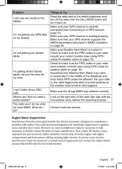
... should arrange for continued FCC technical compliance of an emergency. Check the power connections. Check the master battery switch and branch circuit that all open wires are not in scan mode. I don't know why. I can't read the display. The display flashes, and I can Check your radio. ...Make sure you are adequately covered. ##NOTE: To extend the life of the radio, use waterproof tape to the POSITIVE (+) WIRE of the speaker all wire connections are secure and that connect to transmit on page 37). xx You are not trying to the radio. channel mode (USA...
... should arrange for continued FCC technical compliance of an emergency. Check the power connections. Check the master battery switch and branch circuit that all open wires are not in scan mode. I don't know why. I can't read the display. The display flashes, and I can Check your radio. ...Make sure you are adequately covered. ##NOTE: To extend the life of the radio, use waterproof tape to the POSITIVE (+) WIRE of the speaker all wire connections are secure and that connect to transmit on page 37). xx You are not trying to the radio. channel mode (USA...
English Owners Manual
Page 39
... in some installations it may catch a hazard alert in the middle of the broadcast and miss which FIPS codes are affected. Your radio's DC battery wires, antenna lead, and accessory cables should be necessary to take measures to a GPS receiver, page 31). I'm getting any hazard alerts. hold the CALL-MENU button...
... in some installations it may catch a hazard alert in the middle of the broadcast and miss which FIPS codes are affected. Your radio's DC battery wires, antenna lead, and accessory cables should be necessary to take measures to a GPS receiver, page 31). I'm getting any hazard alerts. hold the CALL-MENU button...


