User Manual
Page 6
... Contents i Table of Contents ii Chapter 1 1 Specifications 1 Mainboard Specifications 2 Mainboard Layout 4 Back Panel Layout 5 Back Panel Ports 6 Slots 6 Onboard Connectors 7 Onboard Jumpers 7 Chapter 2 8 Installation 8 CPU 9 Memory Module Installation 11 Connecting the Power Supply 12 Back Panel Ports 13 Connectors 16 Jumpers 21 Slots 22 Chapter 3 23 BIOS Setup 23 Entering Setup...
... Contents i Table of Contents ii Chapter 1 1 Specifications 1 Mainboard Specifications 2 Mainboard Layout 4 Back Panel Layout 5 Back Panel Ports 6 Slots 6 Onboard Connectors 7 Onboard Jumpers 7 Chapter 2 8 Installation 8 CPU 9 Memory Module Installation 11 Connecting the Power Supply 12 Back Panel Ports 13 Connectors 16 Jumpers 21 Slots 22 Chapter 3 23 BIOS Setup 23 Entering Setup...
User Manual
Page 10
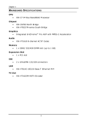
Chapter 1 MAINBOARD SPECIFICATIONS CPU • VIA C7 V4 Bus NanoBGA2 Processor Chipset • VIA CN700 North Bridge • VIA VT8237R-series South Bridge Graphics • Integrated UniChrome™ Pro AGP with MPEG-2 Acceleration Audio • VIA VT1618 8-channel AC'97 Codec Memory • 1 x DDR2 533/400 DIMM slot (up to 1 GB) Expansion Slot • 1 x PCI slot IDE • 2 x UltraDMA 133/100 connectors LAN • VIA VT6103 100/10 Base-T Ethernet PHY TV-Out • VIA VT1625M HDTV Encoder 2
Chapter 1 MAINBOARD SPECIFICATIONS CPU • VIA C7 V4 Bus NanoBGA2 Processor Chipset • VIA CN700 North Bridge • VIA VT8237R-series South Bridge Graphics • Integrated UniChrome™ Pro AGP with MPEG-2 Acceleration Audio • VIA VT1618 8-channel AC'97 Codec Memory • 1 x DDR2 533/400 DIMM slot (up to 1 GB) Expansion Slot • 1 x PCI slot IDE • 2 x UltraDMA 133/100 connectors LAN • VIA VT6103 100/10 Base-T Ethernet PHY TV-Out • VIA VT1625M HDTV Encoder 2

User Manual
Page 11
... (Switchable for KB/MS) • 2 x Fan connectors (CPU Fan and System Fan) • 1 x Front-Panel pin header BIOS • • Award BIOS with 4/8Mbit flash memory capacity ACPI2.0, SMBIOS2.1 and DMI2.2 Form Factor • Mini-ITX (4 layers) • 17 cm X 17 cm 3
... (Switchable for KB/MS) • 2 x Fan connectors (CPU Fan and System Fan) • 1 x Front-Panel pin header BIOS • • Award BIOS with 4/8Mbit flash memory capacity ACPI2.0, SMBIOS2.1 and DMI2.2 Form Factor • Mini-ITX (4 layers) • 17 cm X 17 cm 3
User Manual
Page 14
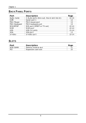
Chapter 1 BACK PANEL PORTS Port Audio Jacks COM PS/2 Mouse PS/2 Keyboard RCA/SPDIF RJ45 USB VGA S-Video Description 3 Audio ports (line-out, line-in and mic-in) Serial port 1 PS/2 mouse port PS/2 keyboard port RCA port (SPDIF or TV out) RJ45 port USB 2.0 ports VGA port S-Video port SLOTS Port DDR DIMM PCI Description Memory module slot Expansion card slot Page 13-15 13 13 13 13-14 13-14 13-14 13 13-14 Page 11 22 6
Chapter 1 BACK PANEL PORTS Port Audio Jacks COM PS/2 Mouse PS/2 Keyboard RCA/SPDIF RJ45 USB VGA S-Video Description 3 Audio ports (line-out, line-in and mic-in) Serial port 1 PS/2 mouse port PS/2 keyboard port RCA port (SPDIF or TV out) RJ45 port USB 2.0 ports VGA port S-Video port SLOTS Port DDR DIMM PCI Description Memory module slot Expansion card slot Page 13-15 13 13 13 13-14 13-14 13-14 13 13-14 Page 11 22 6
User Manual
Page 19
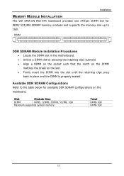
..., 1GB Maximum supported system memory Total 64MB-1GB 64MB-1GB 11 Installation MEMORY MODULE INSTALLATION The VIA EPIA-CN Mini-ITX mainboard provides one 240-pin DIMM slot for available DDR SDRAM configurations on the slot. • Firmly insert the DIMM into the slot until the retaining clips snap back in the motherboard. • Unlock a DIMM slot...
..., 1GB Maximum supported system memory Total 64MB-1GB 64MB-1GB 11 Installation MEMORY MODULE INSTALLATION The VIA EPIA-CN Mini-ITX mainboard provides one 240-pin DIMM slot for available DDR SDRAM configurations on the slot. • Firmly insert the DIMM into the slot until the retaining clips snap back in the motherboard. • Unlock a DIMM slot...

User Manual
Page 38
... 2004 20 : 20 : 20 [None] [QUANTUM FIREBALLP AS] [None] [None] Item Help Menu Level Change the day, month, year and century Halt On Base Memory Extended Memory Total Memory [All , But Keyboard] 640K 195584K 196608K : Move Enter: Select F5: Previous Values +/-/PU/PD: Value F10: Save F6: Fail-Safe Defaults ESC: Exit F1...
... 2004 20 : 20 : 20 [None] [QUANTUM FIREBALLP AS] [None] [None] Item Help Menu Level Change the day, month, year and century Halt On Base Memory Extended Memory Total Memory [All , But Keyboard] 640K 195584K 196608K : Move Enter: Select F5: Previous Values +/-/PU/PD: Value F10: Save F6: Fail-Safe Defaults ESC: Exit F1...

User Manual
Page 46
...used , it can transfer video data at 1066MB/s. Settings: [4x, 2x, 1x] AGP Fast Write This item is a portion of the PCI memory address range dedicated to enable or disable the caching of display data for video purposes. Settings: [Enabled, Disabled] 38 Host cycles that hit the ... the AGP 4x interface. AwardBIOS CMOS Setup Utility AGP & P2P Bridge Control AGP Aperture Size AGP 2.0 Mode AGP Fast Write AGP 3.0 Calibration cycle VGA Share Memory Size Direct Frame Buffer [128M] [4x] [Disabled] [Enabled] [64M] [Enabled] Item Help Menu Level : Move Enter: Select F5: Previous Values +/-/PU...
...used , it can transfer video data at 1066MB/s. Settings: [4x, 2x, 1x] AGP Fast Write This item is a portion of the PCI memory address range dedicated to enable or disable the caching of display data for video purposes. Settings: [Enabled, Disabled] 38 Host cycles that hit the ... the AGP 4x interface. AwardBIOS CMOS Setup Utility AGP & P2P Bridge Control AGP Aperture Size AGP 2.0 Mode AGP Fast Write AGP 3.0 Calibration cycle VGA Share Memory Size Direct Frame Buffer [128M] [4x] [Disabled] [Enabled] [64M] [Enabled] Item Help Menu Level : Move Enter: Select F5: Previous Values +/-/PU...

User Manual
Page 47
AGP 3.0 Calibration Cycle Settings: [Enabled, Disabled] VGA Share Memory Size Settings: [Disabled, 16M, 32M, 64M] Direct Frame Buffer Settings: [Enabled, Disabled] BIOS Setup 39
AGP 3.0 Calibration Cycle Settings: [Enabled, Disabled] VGA Share Memory Size Settings: [Disabled, 16M, 32M, 64M] Direct Frame Buffer Settings: [Enabled, Disabled] BIOS Setup 39
User Manual
Page 52
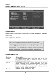
... wakeup-capable devices. ACPI Suspend Type Setting S1(POS) S3(STR) S1 & S3 Description S1/Power On Suspend (POS) is restored from the memory when a "wakeup" event occurs. In this state, no system context (CPU or chipset) is a power-down state. Settings: [Enabled, Disabled] NOTE: ACPI ...is supplied only to main memory, and context is a low power state. S3/Suspend To RAM (STR) is lost and hardware maintains all system contexts. ACPI enables a PC to be turned...
... wakeup-capable devices. ACPI Suspend Type Setting S1(POS) S3(STR) S1 & S3 Description S1/Power On Suspend (POS) is restored from the memory when a "wakeup" event occurs. In this state, no system context (CPU or chipset) is a power-down state. Settings: [Enabled, Disabled] NOTE: ACPI ...is supplied only to main memory, and context is a low power state. S3/Suspend To RAM (STR) is lost and hardware maintains all system contexts. ACPI enables a PC to be turned...
User Manual
Page 60
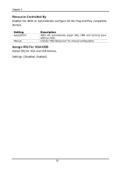
Setting Auto(ESCD) Manual Description BIOS will automatically assign IRQ, DMA and memory base address fields Unlocks "IRQ Resources" for manual configuration Assign IRQ For VGA/USB Assign IRQ for VGA and USB devices. Settings: [Disabled, Enabled] 52 Chapter 3 Resource Controlled By Enables the BIOS to automatically configure all the Plug-and-Play compatible devices.
Setting Auto(ESCD) Manual Description BIOS will automatically assign IRQ, DMA and memory base address fields Unlocks "IRQ Resources" for manual configuration Assign IRQ For VGA/USB Assign IRQ for VGA and USB devices. Settings: [Disabled, Enabled] 52 Chapter 3 Resource Controlled By Enables the BIOS to automatically configure all the Plug-and-Play compatible devices.

User Manual
Page 63
... Latency [DDR/DDR2] This item is for setting the speed it to "Manual". However, if your system becomes less stable, you install new memory that has a different performance rating than the original modules. FREQUENCY / VOLTAGE CONTROL BIOS Setup Phoenix - Changing the value from the factory setting is...Write to complete a command. This field is only available when "DRAM Timing" is not recommended unless you should change it takes for the memory module to Read CMD (Twtr) Write Recovery Time (Twr) DRAM Command Rate RDSAIT mode RDSAIT selection Auto Detect PCI Clk CPU Host/PCIEX/AGP...
... Latency [DDR/DDR2] This item is for setting the speed it to "Manual". However, if your system becomes less stable, you install new memory that has a different performance rating than the original modules. FREQUENCY / VOLTAGE CONTROL BIOS Setup Phoenix - Changing the value from the factory setting is...Write to complete a command. This field is only available when "DRAM Timing" is not recommended unless you should change it takes for the memory module to Read CMD (Twtr) Write Recovery Time (Twr) DRAM Command Rate RDSAIT mode RDSAIT selection Auto Detect PCI Clk CPU Host/PCIEX/AGP...
User Manual
Page 64
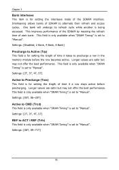
One bank will undergo its refresh cycle while another is set to "Manual". Settings: [Disabled, 2 Bank, 4 Bank, 8 Bank] Precharge to precharge a row in the memory module before precharging. Longer values are safer but may not offer the best performance. This field is only available when "DRAM Timing" is set to "...
One bank will undergo its refresh cycle while another is set to "Manual". Settings: [Disabled, 2 Bank, 4 Bank, 8 Bank] Precharge to precharge a row in the memory module before precharging. Longer values are safer but may not offer the best performance. This field is only available when "DRAM Timing" is set to "...
User Manual
Page 65
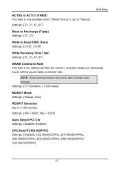
ACT(0) to ACT(1) (TRRD) This field is only available when "DRAM Timing" is for setting how fast the memory controller sends out commands. Settings: [Min = 0000, Max = 003F] Auto Detect PCI Clk Settings: [Disabled, Enabled] CPU Host/PCIEX/AGP/PCI Settings: [Deafault, 133/...57 Lower setting equals faster command rate. Settings: [2T Command, 1T Command] RDSAIT Mode Settings: [Manual, Auto] RDSAIT Selection Key in a HEX number. NOTE: Some memory modules may not be able to "Manual". Settings: [2T, 3T, 4T, 5T] BIOS Setup Read to Precharge (Trptp) Settings: [2T, 3T] Write to Read CMD...
ACT(0) to ACT(1) (TRRD) This field is only available when "DRAM Timing" is for setting how fast the memory controller sends out commands. Settings: [Min = 0000, Max = 003F] Auto Detect PCI Clk Settings: [Disabled, Enabled] CPU Host/PCIEX/AGP/PCI Settings: [Deafault, 133/...57 Lower setting equals faster command rate. Settings: [2T Command, 1T Command] RDSAIT Mode Settings: [Manual, Auto] RDSAIT Selection Key in a HEX number. NOTE: Some memory modules may not be able to "Manual". Settings: [2T, 3T, 4T, 5T] BIOS Setup Read to Precharge (Trptp) Settings: [2T, 3T] Write to Read CMD...
User Manual
Page 69
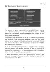
... program can be accessed and the BIOS settings can be confirmed. When a user password is used , the BIOS Setup program can set password from CMOS memory. To disable the password, press when prompted to be changed . To cancel the process press . 61 There are two types of your system configuration. The...
... program can be accessed and the BIOS settings can be confirmed. When a user password is used , the BIOS Setup program can set password from CMOS memory. To disable the password, press when prompted to be changed . To cancel the process press . 61 There are two types of your system configuration. The...