User Manual
Page 6
... Mainboard Specifications 2 Mainboard Layout 4 Back Panel Layout 5 Back Panel Ports 6 Slots 6 Onboard Connectors 7 Onboard Jumpers 7 Chapter 2 8 Installation 8 CPU 9 Memory Module Installation 11 Connecting the Power Supply 12 Back Panel Ports 13 Connectors 16 Jumpers 21 Slots 22 Chapter 3 23 BIOS Setup 23 Entering Setup 24 Control Keys 25 Navigating the BIOS Menus 26 Getting Help 27 Main Menu 28 Standard CMOS Features 30 IDE Drives 31 Advanced BIOS Features 32 Hard Disk Boot Priority 35 Advanced Chipset Features 36 AGP & P2P Bridge Control 38 CPU & PCI Bus Control...
... Mainboard Specifications 2 Mainboard Layout 4 Back Panel Layout 5 Back Panel Ports 6 Slots 6 Onboard Connectors 7 Onboard Jumpers 7 Chapter 2 8 Installation 8 CPU 9 Memory Module Installation 11 Connecting the Power Supply 12 Back Panel Ports 13 Connectors 16 Jumpers 21 Slots 22 Chapter 3 23 BIOS Setup 23 Entering Setup 24 Control Keys 25 Navigating the BIOS Menus 26 Getting Help 27 Main Menu 28 Standard CMOS Features 30 IDE Drives 31 Advanced BIOS Features 32 Hard Disk Boot Priority 35 Advanced Chipset Features 36 AGP & P2P Bridge Control 38 CPU & PCI Bus Control...

User Manual
Page 11
...x S-Video port • 3 x Audio Jacks: line-out, line-in and mic-in (Horizontal, Smart 5.1 Support) Onboard I/O Connectors • 1 x USB pin header for 4 additional USB 2.0 ports • 1 x Front Panel audio pin header (Mic-in and Line-out) • 2 x Serial ATA connectors • 1 x LPT connector • 1 x CD-In pin header • 1 x CIR pin header (Switchable for KB/MS) • 2 x Fan connectors (CPU Fan and System Fan) • 1 x Front-Panel pin header BIOS • • Award BIOS with 4/8Mbit flash memory capacity ACPI2.0, SMBIOS2.1 and DMI2.2 Form Factor • Mini-ITX...
...x S-Video port • 3 x Audio Jacks: line-out, line-in and mic-in (Horizontal, Smart 5.1 Support) Onboard I/O Connectors • 1 x USB pin header for 4 additional USB 2.0 ports • 1 x Front Panel audio pin header (Mic-in and Line-out) • 2 x Serial ATA connectors • 1 x LPT connector • 1 x CD-In pin header • 1 x CIR pin header (Switchable for KB/MS) • 2 x Fan connectors (CPU Fan and System Fan) • 1 x Front-Panel pin header BIOS • • Award BIOS with 4/8Mbit flash memory capacity ACPI2.0, SMBIOS2.1 and DMI2.2 Form Factor • Mini-ITX...
User Manual
Page 14
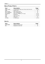
Chapter 1 BACK PANEL PORTS Port Audio Jacks COM PS/2 Mouse PS/2 Keyboard RCA/SPDIF RJ45 USB VGA S-Video Description 3 Audio ports (line-out, line-in and mic-in) Serial port 1 PS/2 mouse port PS/2 keyboard port RCA port (SPDIF or TV out) RJ45 port USB 2.0 ports VGA port S-Video port SLOTS Port DDR DIMM PCI Description Memory module slot Expansion card slot Page 13-15 13 13 13 13-14 13-14 13-14 13 13-14 Page 11 22 6
Chapter 1 BACK PANEL PORTS Port Audio Jacks COM PS/2 Mouse PS/2 Keyboard RCA/SPDIF RJ45 USB VGA S-Video Description 3 Audio ports (line-out, line-in and mic-in) Serial port 1 PS/2 mouse port PS/2 keyboard port RCA port (SPDIF or TV out) RJ45 port USB 2.0 ports VGA port S-Video port SLOTS Port DDR DIMM PCI Description Memory module slot Expansion card slot Page 13-15 13 13 13 13-14 13-14 13-14 13 13-14 Page 11 22 6
User Manual
Page 15
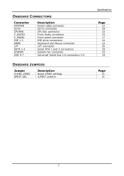
ONBOARD CONNECTORS Connector ATXPWR CD-In CPUFAN F_AUDIO F_PANEL IDE 1-2 KBMS LPT SATA 1-2 SYSFAN USB 4-7 Description Power cable connector CD-In connector CPU fan connector Front Audio connector Front panel connector IDE drive connectors Keyboard and Mouse connector LPT connector Serial ATA 1 and 2 connectors System fan connector Universal Serial Bus 2.0 connectors 3-4 ONBOARD JUMPERS Jumper CLEAR_CMOS SPDIF_SEL Description Reset CMOS settings S/PDIF selector Specifications Page 12 18 10 19 17 16 19 20 18 10 18 Page 21 21 7
ONBOARD CONNECTORS Connector ATXPWR CD-In CPUFAN F_AUDIO F_PANEL IDE 1-2 KBMS LPT SATA 1-2 SYSFAN USB 4-7 Description Power cable connector CD-In connector CPU fan connector Front Audio connector Front panel connector IDE drive connectors Keyboard and Mouse connector LPT connector Serial ATA 1 and 2 connectors System fan connector Universal Serial Bus 2.0 connectors 3-4 ONBOARD JUMPERS Jumper CLEAR_CMOS SPDIF_SEL Description Reset CMOS settings S/PDIF selector Specifications Page 12 18 10 19 17 16 19 20 18 10 18 Page 21 21 7
User Manual
Page 22
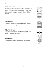
These ports allow connection to external composite video device or audio output device. RCA / SPDIF jack The yellow jack connects to a Local Area Network (LAN) through a network hub and USB 2.0 devices. S-Video port The black port allows you to connect TV monitor or Svideo device to the mainboard. 14 Chapter 2 RJ45 10/100 LAN and USB Connector The mainboard provides a standard RJ-45 and USB 2.0 ports. USB 2.0 ports These two 4-pin Universal Serial Bus (USB) ports are available for connecting USB 2.0 devices.
These ports allow connection to external composite video device or audio output device. RCA / SPDIF jack The yellow jack connects to a Local Area Network (LAN) through a network hub and USB 2.0 devices. S-Video port The black port allows you to connect TV monitor or Svideo device to the mainboard. 14 Chapter 2 RJ45 10/100 LAN and USB Connector The mainboard provides a standard RJ-45 and USB 2.0 ports. USB 2.0 ports These two 4-pin Universal Serial Bus (USB) ports are available for connecting USB 2.0 devices.

User Manual
Page 23
...) Rear (Left/Right) Center/Sub-woofer 15 The Line-In jack is for connecting to a microphone. Shown below are the corresponding connections to external speakers or headphones. You can be switched to the 3-jack connectors on your desktop after installing the audio driver. After completing the previous installation, connect the speakers to Smart 5.1 6-channel audio output. Audio Port: Installation The Line-Out jack is for connecting to setup the 6-channel system.
...) Rear (Left/Right) Center/Sub-woofer 15 The Line-In jack is for connecting to a microphone. Shown below are the corresponding connections to external speakers or headphones. You can be switched to the 3-jack connectors on your desktop after installing the audio driver. After completing the previous installation, connect the speakers to Smart 5.1 6-channel audio output. Audio Port: Installation The Line-Out jack is for connecting to setup the 6-channel system.
User Manual
Page 29
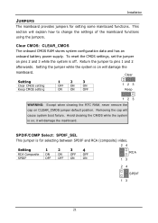
...: Except when clearing the RTC RAM, never remove the cap on will damage the mainboard. Setting the jumper while the system is for setting some mainboard functions. SPDIF/COMP Select: SPDIF_SEL This jumper is on CLEAR_CMOS jumper default position. Clear CMOS: CLEAR_CMOS The onboard CMOS RAM stores system configuration data and has an onboard battery power supply. This section will cause system boot failure. Installation JUMPERS The mainboard provides jumpers for selecting between SPDIF and RCA (composite) video. 24 Setting 1 2 3 4 RCA...
...: Except when clearing the RTC RAM, never remove the cap on will damage the mainboard. Setting the jumper while the system is for setting some mainboard functions. SPDIF/COMP Select: SPDIF_SEL This jumper is on CLEAR_CMOS jumper default position. Clear CMOS: CLEAR_CMOS The onboard CMOS RAM stores system configuration data and has an onboard battery power supply. This section will cause system boot failure. Installation JUMPERS The mainboard provides jumpers for selecting between SPDIF and RCA (composite) video. 24 Setting 1 2 3 4 RCA...
User Manual
Page 30
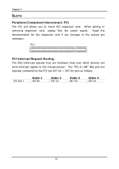
... PCI bus INT A# ~ INT D# pins as follows: PCI Slot 1 Order 1 INT B# Order 2 INT C# Order 3 INT D# Order 4 INT A# 22 The "PCI & LAN" IRQ pins are typically connected to the microprocessor. When adding or removing expansion card, unplug first the power supply. Chapter 2 SLOTS Peripheral Component Interconnect: PCI The PCI slot allows you to the system are necessary. Read the documentation for the expansion card if any changes to insert PCI expansion card...
... PCI bus INT A# ~ INT D# pins as follows: PCI Slot 1 Order 1 INT B# Order 2 INT C# Order 3 INT D# Order 4 INT A# 22 The "PCI & LAN" IRQ pins are typically connected to the microprocessor. When adding or removing expansion card, unplug first the power supply. Chapter 2 SLOTS Peripheral Component Interconnect: PCI The PCI slot allows you to the system are necessary. Read the documentation for the expansion card if any changes to insert PCI expansion card...
User Manual
Page 39
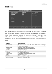
... the menu. AwardBIOS CMOS Setup Utility IDE Channel 0 Master [Press Enter] Item Help IDE Channel 0 Master Access Mode Capacity [Auto] [Auto] 0 MB Menu Level To auto-detect the HDD's size, head... Settings: [None, Auto, Manual] Settings: [CHS, LBA, Large, Auto] Formatted size of the storage device Number of cylinders Number of heads Write precompensation Cylinder location of the landing zone Number of this category. Below is from your drive must match with the drive table. IDE DRIVES BIOS Setup IDE HDD Auto-Detection Phoenix - The hard disk...
... the menu. AwardBIOS CMOS Setup Utility IDE Channel 0 Master [Press Enter] Item Help IDE Channel 0 Master Access Mode Capacity [Auto] [Auto] 0 MB Menu Level To auto-detect the HDD's size, head... Settings: [None, Auto, Manual] Settings: [CHS, LBA, Large, Auto] Formatted size of the storage device Number of cylinders Number of heads Write precompensation Cylinder location of the landing zone Number of this category. Below is from your drive must match with the drive table. IDE DRIVES BIOS Setup IDE HDD Auto-Detection Phoenix - The hard disk...
User Manual
Page 40
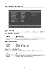
...) Security Option Display Full Screen Logo Display Small Logo [Press Enter] [Disabled] [Enabled] [Enabled] [USB-FDD] [CDROM] [Hard Disk] [Enabled] [On] [Disabled] 6 250 [Setup] [Enabled] [Disabled] Item Help Menu Level Select Hard Disk Boot Device Priority : Move Enter: Select F5: Previous Values +/-/PU/PD: Value F10: Save F6: Fail-Safe Defaults ESC: Exit F1: General F7: Optimized Defaults Help Virus Warning This item is used to enable shorter boot up time. Setting Enabled Disabled Description Turns on hard disk boot sector virus protection Turns off hard disk boot sector...
...) Security Option Display Full Screen Logo Display Small Logo [Press Enter] [Disabled] [Enabled] [Enabled] [USB-FDD] [CDROM] [Hard Disk] [Enabled] [On] [Disabled] 6 250 [Setup] [Enabled] [Disabled] Item Help Menu Level Select Hard Disk Boot Device Priority : Move Enter: Select F5: Previous Values +/-/PU/PD: Value F10: Save F6: Fail-Safe Defaults ESC: Exit F1: General F7: Optimized Defaults Help Virus Warning This item is used to enable shorter boot up time. Setting Enabled Disabled Description Turns on hard disk boot sector virus protection Turns off hard disk boot sector...
User Manual
Page 41
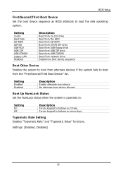
... fails to load the disk operating system. Setting LS120 Hard Disk CD-ROM ZIP100 USB-FDD USB-ZIP USB-CDROM Legacy LAN Disabled Description Boot from LS-120 drive Boot from the HDD Boot from CD-ROM Boot from ATAPI ZIP drive Boot from USB floppy drive Boot from USB ZIP drive Boot from USB CDROM Boot from network drive Disable the boot device sequence Boot Other Device Enables the system to boot from the "First/Second/Third Boot Device" list. BIOS Setup First/Second/Third Boot Device Set the boot device sequence as arrow keys Typematic Rate Setting Enables "Typematic Rate...
... fails to load the disk operating system. Setting LS120 Hard Disk CD-ROM ZIP100 USB-FDD USB-ZIP USB-CDROM Legacy LAN Disabled Description Boot from LS-120 drive Boot from the HDD Boot from CD-ROM Boot from ATAPI ZIP drive Boot from USB floppy drive Boot from USB ZIP drive Boot from USB CDROM Boot from network drive Disable the boot device sequence Boot Other Device Enables the system to boot from the "First/Second/Third Boot Device" list. BIOS Setup First/Second/Third Boot Device Set the boot device sequence as arrow keys Typematic Rate Setting Enables "Typematic Rate...

User Manual
Page 42
... when the system begins to run BIOS Setup Display Full Screen Logo Show full screen logo during BIOS boot up process. Settings: [Enabled, Disabled] Display Small Logo Show small energy star logo during BIOS boot up process. Settings: [Enabled, Disabled] 34 Settings: [250, 500, 750, 1000] Security Option Selects whether the password is powered on and when end users try to repeat the signal from a depressed key. Chapter 3 Typematic Rate (Chars/Sec...
... when the system begins to run BIOS Setup Display Full Screen Logo Show full screen logo during BIOS boot up process. Settings: [Enabled, Disabled] Display Small Logo Show small energy star logo during BIOS boot up process. Settings: [Enabled, Disabled] 34 Settings: [250, 500, 750, 1000] Security Option Selects whether the password is powered on and when end users try to repeat the signal from a depressed key. Chapter 3 Typematic Rate (Chars/Sec...

User Manual
Page 44
AwardBIOS CMOS Setup Utility Advanced Chipset Features Display Card Priority AGP & P2P Bridge Control CPU & PCI Bus Control AGP Driving Control AGP Driving Value Select Display Device TV H/W Layout TV Type TV Output Connector [PCI Slot] [Press Enter] [Press Enter] [Auto] DA [CRT] [Default] [NTSC] [Press Enter] Item Help Menu Level If there are familiar with the system. Settings: [Auto, Manual] AGP Driving Value Key in a HEX number. Settings: [PCI Slot and AGP] AGP Driving Control This item is used for BIOS to auto or manual. Settings: [Min = 0000, Max = 00FF] Select Display Device ...
AwardBIOS CMOS Setup Utility Advanced Chipset Features Display Card Priority AGP & P2P Bridge Control CPU & PCI Bus Control AGP Driving Control AGP Driving Value Select Display Device TV H/W Layout TV Type TV Output Connector [PCI Slot] [Press Enter] [Press Enter] [Auto] DA [CRT] [Default] [NTSC] [Press Enter] Item Help Menu Level If there are familiar with the system. Settings: [Auto, Manual] AGP Driving Value Key in a HEX number. Settings: [PCI Slot and AGP] AGP Driving Control This item is used for BIOS to auto or manual. Settings: [Min = 0000, Max = 00FF] Select Display Device ...

User Manual
Page 46
... the default 4x mode on. When the AGP 4x video card is used , it can transfer video data at 1066MB/s. Settings: [32MB, 64MB, 128MB, 256MB, 512MB, 1G] AGP 2.0 Mode This mainboard supports the AGP 4x interface. AwardBIOS CMOS Setup Utility AGP & P2P Bridge Control AGP Aperture Size AGP 2.0 Mode AGP Fast Write AGP 3.0 Calibration cycle VGA Share Memory Size Direct Frame Buffer [128M] [4x] [Disabled] [Enabled] [64M] [Enabled] Item Help Menu Level : Move Enter...
... the default 4x mode on. When the AGP 4x video card is used , it can transfer video data at 1066MB/s. Settings: [32MB, 64MB, 128MB, 256MB, 512MB, 1G] AGP 2.0 Mode This mainboard supports the AGP 4x interface. AwardBIOS CMOS Setup Utility AGP & P2P Bridge Control AGP Aperture Size AGP 2.0 Mode AGP Fast Write AGP 3.0 Calibration cycle VGA Share Memory Size Direct Frame Buffer [128M] [4x] [Disabled] [Enabled] [64M] [Enabled] Item Help Menu Level : Move Enter...
User Manual
Page 50
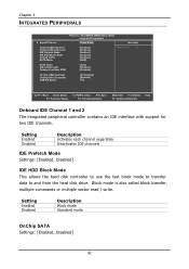
... hard disk controller to use the fast block mode to transfer data to and from the hard disk drive. Chapter 3 INTEGRATED PERIPHERALS SuperIO Device Onboard IDE Channel 1 Onboard IDE Channel 2 IDE Prefetch Mode IDE HDD Block Mode OnChip SATA SATA Mode Phoenix - Block mode is also called block transfer, multiple commands or multiple sector read / write. AwardBIOS CMOS Setup Utility Integrated Peripherals [Press Enter] Item Help [Enabled] [Enabled] [Enabled] [Enabled] [Enabled] [RAID] Menu Level AC97 Audio VIA OnChip LAN Onboard Lan Boot ROM [Auto] [Enabled] [Disabled] OnChip USB...
... hard disk controller to use the fast block mode to transfer data to and from the hard disk drive. Chapter 3 INTEGRATED PERIPHERALS SuperIO Device Onboard IDE Channel 1 Onboard IDE Channel 2 IDE Prefetch Mode IDE HDD Block Mode OnChip SATA SATA Mode Phoenix - Block mode is also called block transfer, multiple commands or multiple sector read / write. AwardBIOS CMOS Setup Utility Integrated Peripherals [Press Enter] Item Help [Enabled] [Enabled] [Enabled] [Enabled] [Enabled] [RAID] Menu Level AC97 Audio VIA OnChip LAN Onboard Lan Boot ROM [Auto] [Enabled] [Disabled] OnChip USB...
User Manual
Page 51
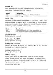
... set to "ON", support USB legacy keyboard, mouse and storage. BIOS Setup SATA Mode Serial ATA is the latest generation of up to 150MB/sec. Setting Auto Disabled Description Enables onboard controller if audio device is detected Turn off onboard controller to allow external controller VIA OnChip LAN Settings: [Enabled, Disabled] Onboard Lan Boot ROM Settings: [Enabled, Disabled] OnChip USB Controller Settings: [All Disabled, All Enabled, 1&2 USB Port, 2&3 USB Port, 1&3 USB Port, 1 USB Port, 2 USB Port, 3 USB Port] OnChip EHCI Controller Settings: [Enabled, Disabled] USB Emulation Set...
... set to "ON", support USB legacy keyboard, mouse and storage. BIOS Setup SATA Mode Serial ATA is the latest generation of up to 150MB/sec. Setting Auto Disabled Description Enables onboard controller if audio device is detected Turn off onboard controller to allow external controller VIA OnChip LAN Settings: [Enabled, Disabled] Onboard Lan Boot ROM Settings: [Enabled, Disabled] OnChip USB Controller Settings: [All Disabled, All Enabled, 1&2 USB Port, 2&3 USB Port, 1&3 USB Port, 1 USB Port, 2 USB Port, 3 USB Port] OnChip EHCI Controller Settings: [Enabled, Disabled] USB Emulation Set...
User Manual
Page 59
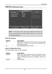
AwardBIOS CMOS Setup Utility PnP / PCI Configurations PNP OS Installed Reset Configuration Data Resources Controlled By IRQ Resources Assign IRQ For VGA Assign IRQ For USB [No] [Disabled] [Auto(ESCD)] Press Enter [Enabled] [Enabled] Item Help Menu Level Select Yes if you are using a Plug and Play capable operating system. The rest of the cards will be left "Disabled". PNP/PCI CONFIGURATIONS BIOS Setup Phoenix - Select No if you need the BIOS to configure non-boot devices : Move Enter: Select F5...
AwardBIOS CMOS Setup Utility PnP / PCI Configurations PNP OS Installed Reset Configuration Data Resources Controlled By IRQ Resources Assign IRQ For VGA Assign IRQ For USB [No] [Disabled] [Auto(ESCD)] Press Enter [Enabled] [Enabled] Item Help Menu Level Select Yes if you are using a Plug and Play capable operating system. The rest of the cards will be left "Disabled". PNP/PCI CONFIGURATIONS BIOS Setup Phoenix - Select No if you need the BIOS to configure non-boot devices : Move Enter: Select F5...

User Manual
Page 63
... 25T 3T [2T] [1T/2T] [4T] [2T Command] [Auto] 03 [Enabled] [Default] [ 6 X] [Disabled] Item Help Menu Level : Move Enter: Select F5: Previous Values +/-/PU/PD: Value F10: Save F6: Fail-Safe Defaults ESC: Exit F1: General F7: Optimized Defaults Help DRAM Clock The chipset supports synchronous and asynchronous mode between host clock and DRAM clock frequency. Settings: [1.5/2, 2/3, 2.5/4, 3/5] 55 FREQUENCY / VOLTAGE CONTROL BIOS Setup Phoenix - AwardBIOS CMOS Setup Utility Frequency / Voltage Control DRAM Clock DRAM Timing SDRAM CAS Latency [DDR/DDR2] Bank Interleave Precharge...
... 25T 3T [2T] [1T/2T] [4T] [2T Command] [Auto] 03 [Enabled] [Default] [ 6 X] [Disabled] Item Help Menu Level : Move Enter: Select F5: Previous Values +/-/PU/PD: Value F10: Save F6: Fail-Safe Defaults ESC: Exit F1: General F7: Optimized Defaults Help DRAM Clock The chipset supports synchronous and asynchronous mode between host clock and DRAM clock frequency. Settings: [1.5/2, 2/3, 2.5/4, 3/5] 55 FREQUENCY / VOLTAGE CONTROL BIOS Setup Phoenix - AwardBIOS CMOS Setup Utility Frequency / Voltage Control DRAM Clock DRAM Timing SDRAM CAS Latency [DDR/DDR2] Bank Interleave Precharge...

User Manual
Page 75
If the CD does not run automatically after closing the CD-ROM or DVD-ROM drive. Driver Installation Running the Driver Utilities CD To start using the CD, insert the CD into the CD-ROM or DVD-ROM drive. The CD should then appear on the "Start" button and select "Run..." Then type: "D:\Setup.exe". The driver utilities and software menu screen should run automatically, click on the screen. NOTE: D: might not be the drive letter of the CD-ROM/DVD-ROM in your system. 67
If the CD does not run automatically after closing the CD-ROM or DVD-ROM drive. Driver Installation Running the Driver Utilities CD To start using the CD, insert the CD into the CD-ROM or DVD-ROM drive. The CD should then appear on the "Start" button and select "Run..." Then type: "D:\Setup.exe". The driver utilities and software menu screen should run automatically, click on the screen. NOTE: D: might not be the drive letter of the CD-ROM/DVD-ROM in your system. 67
User Manual
Page 76
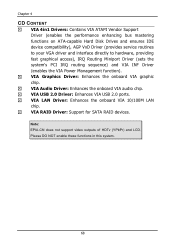
... the onboard VIA 10/100M LAN chip. VIA Audio Driver: Enhances the onboard VIA audio chip. Note: EPIA-CN does not support video outputs of HDTv (YPbPr) and LCD. VIA USB 2.0 Driver: Enhances VIA USB 2.0 ports. Please DO NOT enable these functions in this system. 68 VIA RAID Driver: Support for SATA RAID devices. Chapter 4 CD CONTENT VIA 4in1 Drivers: Contains VIA ATAPI Vendor Support Driver (enables the performance enhancing bus mastering functions on ATA-capable Hard Disk Drives and ensures IDE device compatibility), AGP VxD Driver (provides service routines to your VGA driver and...
... the onboard VIA 10/100M LAN chip. VIA Audio Driver: Enhances the onboard VIA audio chip. Note: EPIA-CN does not support video outputs of HDTv (YPbPr) and LCD. VIA USB 2.0 Driver: Enhances VIA USB 2.0 ports. Please DO NOT enable these functions in this system. 68 VIA RAID Driver: Support for SATA RAID devices. Chapter 4 CD CONTENT VIA 4in1 Drivers: Contains VIA ATAPI Vendor Support Driver (enables the performance enhancing bus mastering functions on ATA-capable Hard Disk Drives and ensures IDE device compatibility), AGP VxD Driver (provides service routines to your VGA driver and...
