Specifications
Page 1
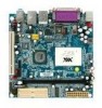
Mini-ITX Series VIA EPIA EK Mini-ITX Luke Board with MPEG-2 & 4, 4 COM Ports & Dual LAN Features „„Integrated VIA UniChrome™ Pro AGP graphics with MPEG2/4 decoding acceleration „„Supports DDR400 ...Memory VGA Expansion Slot Onboard IDE Onboard Audio Onboard Serial ATA Onboard I/O Connectors Back Panel I/O BIOS Operating System Software Application EPIA EK10000G EPIA EK10000LG* EPIA EK8000EG EPIA EK8000ELG* 1.0GHz VIA Luke 1.0GHz VIA Luke 800MHz VIA Luke 800MHz VIA Luke VIA VT8237R Plus South Bridge VIA VT8237R Plus South Bridge VIA VT8237R Plus South Bridge VIA...
Mini-ITX Series VIA EPIA EK Mini-ITX Luke Board with MPEG-2 & 4, 4 COM Ports & Dual LAN Features „„Integrated VIA UniChrome™ Pro AGP graphics with MPEG2/4 decoding acceleration „„Supports DDR400 ...Memory VGA Expansion Slot Onboard IDE Onboard Audio Onboard Serial ATA Onboard I/O Connectors Back Panel I/O BIOS Operating System Software Application EPIA EK10000G EPIA EK10000LG* EPIA EK8000EG EPIA EK8000ELG* 1.0GHz VIA Luke 1.0GHz VIA Luke 800MHz VIA Luke 800MHz VIA Luke VIA VT8237R Plus South Bridge VIA VT8237R Plus South Bridge VIA VT8237R Plus South Bridge VIA...

Specifications
Page 2
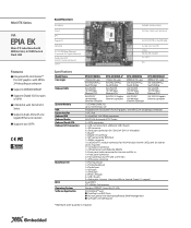
... power failure recovery 0°C ~ 50°C 0% ~ 95% (relative humidity; non-condensing) Mini-ITX (6-layer). 17 cm x 17 cm Ordering Information Model Name EK10000G CPU Frequency 1.0GHz Luke EK8000EG 800MHz Luke EK10000LG 1.0GHz Luke EK8000ELG 800MHz Luke Description Mini-ITX Board with 1.0GHz Luke Processing Unit, VGA, USB, 4 x COM, LPT, Dual LAN, ... IDE BUS USB AC97 Codec VT1618 24.576 MHz AC97 KB/MOUSE LAN VT6103L PHY COM1 COM2 Luke XTAL CLOCK GENERATOR ICS 950913 MEMORY BUS 100 ~ 200 MHz DDR 266/333/400 DIMM V-LINK 66 MHz VT8237R Plus PCI BUS 33 MHz LPC BUS LPC 33...
... power failure recovery 0°C ~ 50°C 0% ~ 95% (relative humidity; non-condensing) Mini-ITX (6-layer). 17 cm x 17 cm Ordering Information Model Name EK10000G CPU Frequency 1.0GHz Luke EK8000EG 800MHz Luke EK10000LG 1.0GHz Luke EK8000ELG 800MHz Luke Description Mini-ITX Board with 1.0GHz Luke Processing Unit, VGA, USB, 4 x COM, LPT, Dual LAN, ... IDE BUS USB AC97 Codec VT1618 24.576 MHz AC97 KB/MOUSE LAN VT6103L PHY COM1 COM2 Luke XTAL CLOCK GENERATOR ICS 950913 MEMORY BUS 100 ~ 200 MHz DDR 266/333/400 DIMM V-LINK 66 MHz VT8237R Plus PCI BUS 33 MHz LPC BUS LPC 33...

User Manual
Page 6
... Contents i Table of Contents ii Chapter 1 1 Specifications 1 Mainboard Specifications 2 Mainboard Layout 4 Back Panel Layout 5 Back Panel Ports 6 Slots 6 Onboard Connectors 7 Onboard Jumpers 7 Chapter 2 8 Installation 8 CPU 9 Memory Module Installation 11 Connecting the Power Supply 12 Back Panel Ports 13 Connectors 16 Jumpers 24 Slots 26 Chapter 3 27 BIOS Setup 27 Entering Setup...
... Contents i Table of Contents ii Chapter 1 1 Specifications 1 Mainboard Specifications 2 Mainboard Layout 4 Back Panel Layout 5 Back Panel Ports 6 Slots 6 Onboard Connectors 7 Onboard Jumpers 7 Chapter 2 8 Installation 8 CPU 9 Memory Module Installation 11 Connecting the Power Supply 12 Back Panel Ports 13 Connectors 16 Jumpers 24 Slots 26 Chapter 3 27 BIOS Setup 27 Entering Setup...

User Manual
Page 10
Chapter 1 MAINBOARD SPECIFICATIONS CPU • VIA Luke CoreFusion™ Processor Chipset • VIA VT8237R-series South Bridge Graphics • Integrated UniChrome™ Pro AGP with MPEG-2 Acceleration Audio • VIA VT1618 AC'97 Codec with 6-channel support Memory • 1 x DDR 400 DIMM slot (up to 1 GB) Expansion Slot • 1 x PCI slot IDE • 2 x UltraDMA 133/100 connectors LAN • • VIA VT6103L 10/100 Ethernet PHY VIA VT6107 10/100 Fast Ethernet (default) or VT6122 Gigabit Ethernet Controller 2
Chapter 1 MAINBOARD SPECIFICATIONS CPU • VIA Luke CoreFusion™ Processor Chipset • VIA VT8237R-series South Bridge Graphics • Integrated UniChrome™ Pro AGP with MPEG-2 Acceleration Audio • VIA VT1618 AC'97 Codec with 6-channel support Memory • 1 x DDR 400 DIMM slot (up to 1 GB) Expansion Slot • 1 x PCI slot IDE • 2 x UltraDMA 133/100 connectors LAN • • VIA VT6103L 10/100 Ethernet PHY VIA VT6107 10/100 Fast Ethernet (default) or VT6122 Gigabit Ethernet Controller 2

User Manual
Page 11
... pin header • 1 x LVDS_DVI pin header for 24-bit/Dual 12-bit LVDS interface selection • 1 x Buzzer BIOS • • Award BIOS with 2/4/8Mbit flash memory capacity ACPI1.0b, SMBIOS2.3 and DMI2.1 Form Factor • Mini-ITX (6 layers) • 17 cm X 17 cm 3
... pin header • 1 x LVDS_DVI pin header for 24-bit/Dual 12-bit LVDS interface selection • 1 x Buzzer BIOS • • Award BIOS with 2/4/8Mbit flash memory capacity ACPI1.0b, SMBIOS2.3 and DMI2.1 Form Factor • Mini-ITX (6 layers) • 17 cm X 17 cm 3

User Manual
Page 19
Installation MEMORY MODULE INSTALLATION The VIA EPIA-EK Mini-ITX mainboard provides one 184-pin DIMM slot for available DDR SDRAM configurations on the slot. • Firmly insert the DIMM into the slot until the ... up to 1GB. Slot Module Size DIMM 64MB, 128MB, 256MB, 512MB, 1GB Maximum supported system memory Total 64MB-1GB 64MB-1GB 11 DIMM DDR SDRAM Module Installation Procedures • Locate the DIMM slot in the motherboard. • Unlock a DIMM slot by pressing the retaining clips outward. • Align a DIMM on the socket...
Installation MEMORY MODULE INSTALLATION The VIA EPIA-EK Mini-ITX mainboard provides one 184-pin DIMM slot for available DDR SDRAM configurations on the slot. • Firmly insert the DIMM into the slot until the ... up to 1GB. Slot Module Size DIMM 64MB, 128MB, 256MB, 512MB, 1GB Maximum supported system memory Total 64MB-1GB 64MB-1GB 11 DIMM DDR SDRAM Module Installation Procedures • Locate the DIMM slot in the motherboard. • Unlock a DIMM slot by pressing the retaining clips outward. • Align a DIMM on the socket...

User Manual
Page 42
... 2004 20 : 20 : 20 [None] [QUANTUM FIREBALLP AS] [None] [None] Item Help Menu Level Change the day, month, year and century Halt On Base Memory Extended Memory Total Memory [All , But Keyboard] 640K 195584K 196608K : Move Enter: Select +/-/PU/PD: Value F10: Save F5: Previous Values F6: Fail-Safe Defaults ESC: Exit F1...
... 2004 20 : 20 : 20 [None] [QUANTUM FIREBALLP AS] [None] [None] Item Help Menu Level Change the day, month, year and century Halt On Base Memory Extended Memory Total Memory [All , But Keyboard] 640K 195584K 196608K : Move Enter: Select +/-/PU/PD: Value F10: Save F5: Previous Values F6: Fail-Safe Defaults ESC: Exit F1...

User Manual
Page 50
... range dedicated to AGP for video purposes. AwardBIOS CMOS Setup Utility AGP & P2P Bridge Control AGP Aperture Size AGP 2.0 Mode VGA Share Memory Size Direct Frame Buffer [128M] [4x] [64M] [Enabled] Item Help Menu Level : Move Enter: Select +/-/PU/PD: Value F10: Save F5: Previous ...Values F6: Fail-Safe Defaults ESC: Exit F1: General Help F7: Optimized Defaults AGP Aperture Size This setting controls how much memory space can be allocated to graphics memory address space. Host cycles that hit the aperture range are forwarded to the AGP without any translation. Chapter 3 AGP & P2P ...
... range dedicated to AGP for video purposes. AwardBIOS CMOS Setup Utility AGP & P2P Bridge Control AGP Aperture Size AGP 2.0 Mode VGA Share Memory Size Direct Frame Buffer [128M] [4x] [64M] [Enabled] Item Help Menu Level : Move Enter: Select +/-/PU/PD: Value F10: Save F5: Previous ...Values F6: Fail-Safe Defaults ESC: Exit F1: General Help F7: Optimized Defaults AGP Aperture Size This setting controls how much memory space can be allocated to graphics memory address space. Host cycles that hit the aperture range are forwarded to the AGP without any translation. Chapter 3 AGP & P2P ...

User Manual
Page 57
... S1(POS): System in low power mode S3(STR): All components are powered off except memory. The system context is saved to select S1 or S3. S1 & S3: Depends on the OS to main memory, and context is a power-down the hard disk. AwardBIOS CMOS Setup Utility Power Management Setup...(POS)] [Disabled] [Disabled] [Suspend -> Off] [Instant-Off] [Auto] [Off] Item Help Menu Level This item allows you to essential components such as main memory and wakeup-capable devices. In this state, no system context (CPU or chipset) is lost and hardware maintains all system contexts. In this state, power...
... S1(POS): System in low power mode S3(STR): All components are powered off except memory. The system context is saved to select S1 or S3. S1 & S3: Depends on the OS to main memory, and context is a power-down the hard disk. AwardBIOS CMOS Setup Utility Power Management Setup...(POS)] [Disabled] [Disabled] [Suspend -> Off] [Instant-Off] [Auto] [Off] Item Help Menu Level This item allows you to essential components such as main memory and wakeup-capable devices. In this state, no system context (CPU or chipset) is lost and hardware maintains all system contexts. In this state, power...

User Manual
Page 64
..., Enabled] 56 Chapter 3 Reset Configuration Data This field should usually be left "Disabled". Setting Auto(ESCD) Manual Description BIOS will automatically assign IRQ, DMA and memory base address fields Unlocks "IRQ Resources" for manual configuration Assign IRQ For VGA/USB Assign IRQ for VGA and USB devices. Setting Enabled Disabled Description...
..., Enabled] 56 Chapter 3 Reset Configuration Data This field should usually be left "Disabled". Setting Auto(ESCD) Manual Description BIOS will automatically assign IRQ, DMA and memory base address fields Unlocks "IRQ Resources" for manual configuration Assign IRQ For VGA/USB Assign IRQ for VGA and USB devices. Setting Enabled Disabled Description...
User Manual
Page 67
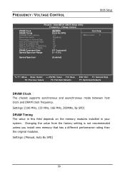
Settings: [100 MHz, 133 MHz, 166 MHz, 200MHz, By SPD] DRAM Timing The value in this field depends on the memory modules installed in your system. Settings: [Manual, Auto By SPD] 59 AwardBIOS CMOS Setup Utility Frequency / Voltage Control DRAM Clock DRAM Timing SDRAM CAS Latency ... synchronous and asynchronous mode between host clock and DRAM clock frequency. Changing the value from the factory setting is not recommended unless you install new memory that has a different performance rating than the original modules. FREQUENCY / VOLTAGE CONTROL BIOS Setup Phoenix -
Settings: [100 MHz, 133 MHz, 166 MHz, 200MHz, By SPD] DRAM Timing The value in this field depends on the memory modules installed in your system. Settings: [Manual, Auto By SPD] 59 AwardBIOS CMOS Setup Utility Frequency / Voltage Control DRAM Clock DRAM Timing SDRAM CAS Latency ... synchronous and asynchronous mode between host clock and DRAM clock frequency. Changing the value from the factory setting is not recommended unless you install new memory that has a different performance rating than the original modules. FREQUENCY / VOLTAGE CONTROL BIOS Setup Phoenix -

User Manual
Page 68
...another is for setting the interleave mode of your system becomes less stable, you should change it to precharge a row in the memory module before precharging. One bank will improve the performance of the SDRAM interface. This improves performance of the SDRAM by masking the... values are safer but may not offer the best performance. Chapter 3 SDRAM CAS Latency This item is for setting the speed it takes for the memory module to "Manual". Settings: [1.5, 2, 2.5, 3] Bank Interleave This item is being accessed. However, if your system. Settings: [Disabled, 2 Bank, 4 Bank] ...
...another is for setting the interleave mode of your system becomes less stable, you should change it to precharge a row in the memory module before precharging. One bank will improve the performance of the SDRAM interface. This improves performance of the SDRAM by masking the... values are safer but may not offer the best performance. Chapter 3 SDRAM CAS Latency This item is for setting the speed it takes for the memory module to "Manual". Settings: [1.5, 2, 2.5, 3] Bank Interleave This item is being accessed. However, if your system. Settings: [Disabled, 2 Bank, 4 Bank] ...

User Manual
Page 69
..., 13T, 14T, 15T] BIOS Setup ACT(0) to ACT(1) (TRRD) This field is only available when "DRAM Timing" is set to "Manual". Note: Some memory modules may not be able to handle lower settings. Settings: [Disabled, Enabled] 61 Lower setting equals faster command rate. Settings: [2T Command, 1T Command] Spread... values (spikes) of the pulses are reduced to flatter curves. Settings: [2T, 3T] DRAM Command Rate This field is for setting how fast the memory controller sends out commands. REF to ACT / REF (Trfc) This field is only available when "DRAM Timing" is set to "Manual". The Spread...
..., 13T, 14T, 15T] BIOS Setup ACT(0) to ACT(1) (TRRD) This field is only available when "DRAM Timing" is set to "Manual". Note: Some memory modules may not be able to handle lower settings. Settings: [Disabled, Enabled] 61 Lower setting equals faster command rate. Settings: [2T Command, 1T Command] Spread... values (spikes) of the pulses are reduced to flatter curves. Settings: [2T, 3T] DRAM Command Rate This field is for setting how fast the memory controller sends out commands. REF to ACT / REF (Trfc) This field is only available when "DRAM Timing" is set to "Manual". The Spread...

User Manual
Page 72
When a password has been set the password, type the password (up to be changed . This prevents an unauthorized person from CMOS memory. The new password will need to be reentered to eight characters in BIOS F10 : Save & Exit Setup : Select Item Change / Set / Disable Password This option ...
When a password has been set the password, type the password (up to be changed . This prevents an unauthorized person from CMOS memory. The new password will need to be reentered to eight characters in BIOS F10 : Save & Exit Setup : Select Item Change / Set / Disable Password This option ...