User Manual
Page 2
...Technologies Ltd. FCC-B Radio Frequency Interference Statement This equipment has been tested and found to correct the interference at his personal expense. power cord, if any, must be used in accordance with the instruction manual, may be reproduced, transmitted, transcribed, stored in a ...or otherwise without the prior written permission of the FCC rules. Operation of this document may cause harmful interference to part 15 of VIA Technologies, Incorporated. This equipment generates, uses and can radiate radio frequency energy and, if not installed and used in a commercial...
...Technologies Ltd. FCC-B Radio Frequency Interference Statement This equipment has been tested and found to correct the interference at his personal expense. power cord, if any, must be used in accordance with the instruction manual, may be reproduced, transmitted, transcribed, stored in a ...or otherwise without the prior written permission of the FCC rules. Operation of this document may cause harmful interference to part 15 of VIA Technologies, Incorporated. This equipment generates, uses and can radiate radio frequency energy and, if not installed and used in a commercial...
User Manual
Page 3
...8226; The equipment has been exposed to moisture • The equipment has not work according to local regulations. Do not attempt to the power inlet. 7. Do not discard used batteries according to User's Manual. • The equipment has dropped and damaged • If the ..., STORAGE TEMPERATURE ABOVE 60 C (140F), IT MAY DAMAGE THE EQUIPMENT. Keep this equipment on card or module. 9. Always unplug the power cord before connecting the equipment to force open the battery. Lay this equipment away from overheating. Caution: Only use the appropriate battery specified...
...8226; The equipment has been exposed to moisture • The equipment has not work according to local regulations. Do not attempt to the power inlet. 7. Do not discard used batteries according to User's Manual. • The equipment has dropped and damaged • If the ..., STORAGE TEMPERATURE ABOVE 60 C (140F), IT MAY DAMAGE THE EQUIPMENT. Keep this equipment on card or module. 9. Always unplug the power cord before connecting the equipment to force open the battery. Lay this equipment away from overheating. Caution: Only use the appropriate battery specified...

User Manual
Page 6
... 1 Mainboard Specifications 2 Mainboard Layout 5 Back Panel Layout 6 Back Panel Ports 7 Slots 7 Onboard Connectors 8 Onboard Jumpers 8 Chapter 2 9 Installation 9 CPU 10 Memory Module Installation 12 Connecting the Power Supply 13 Back Panel Ports 14 Connectors 17 Jumpers 25 Slots 27 Chapter 3 29 BIOS Setup 29 Entering Setup 30 Control Keys 31 Navigating the...
... 1 Mainboard Specifications 2 Mainboard Layout 5 Back Panel Layout 6 Back Panel Ports 7 Slots 7 Onboard Connectors 8 Onboard Jumpers 8 Chapter 2 9 Installation 9 CPU 10 Memory Module Installation 12 Connecting the Power Supply 13 Back Panel Ports 14 Connectors 17 Jumpers 25 Slots 27 Chapter 3 29 BIOS Setup 29 Entering Setup 30 Control Keys 31 Navigating the...

User Manual
Page 7
CPU & PCI Bus Control 50 TV Output Connector 51 Integrated Peripherals 52 Super IO Device 54 Power Management Setup 55 Peripheral Activities 57 IRQs Activities 60 PNP/PCI Configurations 61 IRQ Resources 63 PC Health Status 64 Frequency / Voltage Control 65 Load Fail-Safe Defaults 69 Load Optimized Defaults 70 Set Supervisor / User Password 71 Save & Exit Setup 73 Exit Without Saving 74 Chapter 4 75 Driver Installation 75 Driver Utilities 76 CD Content 78 iii
CPU & PCI Bus Control 50 TV Output Connector 51 Integrated Peripherals 52 Super IO Device 54 Power Management Setup 55 Peripheral Activities 57 IRQs Activities 60 PNP/PCI Configurations 61 IRQ Resources 63 PC Health Status 64 Frequency / Voltage Control 65 Load Fail-Safe Defaults 69 Load Optimized Defaults 70 Set Supervisor / User Password 71 Save & Exit Setup 73 Exit Without Saving 74 Chapter 4 75 Driver Installation 75 Driver Utilities 76 CD Content 78 iii

User Manual
Page 9
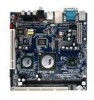
CHAPTER 1 Specifications The ultra-compact and highly integrated VIA EPIA-EN uses the Mini-ITX mainboard form-factor developed by VIA Technologies, Inc. as part of FlexATX mainboard form factor. The mainboard enables the creation of an exciting new generation of small, ergonomic, innovative and affordable embedded systems. Through a high level of integration, the Mini-ITX occupy 66% of the size of the company's open industry-wide total connectivity initiative. The mainboard comes with an embedded VIA Processor, boasting of ultra-low power consumption, cool and quite operation. 1
CHAPTER 1 Specifications The ultra-compact and highly integrated VIA EPIA-EN uses the Mini-ITX mainboard form-factor developed by VIA Technologies, Inc. as part of FlexATX mainboard form factor. The mainboard enables the creation of an exciting new generation of small, ergonomic, innovative and affordable embedded systems. Through a high level of integration, the Mini-ITX occupy 66% of the size of the company's open industry-wide total connectivity initiative. The mainboard comes with an embedded VIA Processor, boasting of ultra-low power consumption, cool and quite operation. 1

User Manual
Page 16
... Connector 1394 ATXPWR COM 2 CPUFAN SIR F_AUDIO F_PANEL IDE 1-2 KBMS LPC/SIR LVDS/TTL/DVI SATA 1-2 SPDIF 1-2 SMBus SYSFAN USB 5-6 TV Description IEEE 1394 connector Power cable connector COM port 2 connector CPU fan connector Fast Infrared Radiation connector Front Audio connector Front panel connector IDE drive connectors Keyboard and Mouse connector...
... Connector 1394 ATXPWR COM 2 CPUFAN SIR F_AUDIO F_PANEL IDE 1-2 KBMS LPC/SIR LVDS/TTL/DVI SATA 1-2 SPDIF 1-2 SMBus SYSFAN USB 5-6 TV Description IEEE 1394 connector Power cable connector COM port 2 connector CPU fan connector Fast Infrared Radiation connector Front Audio connector Front panel connector IDE drive connectors Keyboard and Mouse connector...
User Manual
Page 21
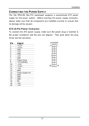
... are installed correctly to ensure that all components are aligned. Then push down the plug firmly into the connector. Installation CONNECTING THE POWER SUPPLY The VIA EPIA-EN Mini-ITX mainboard supports a conventional ATX power supply for the power system. ATX 20-Pin Power Connector To connect the ATX power supply, make sure that no damage will be caused.
... are installed correctly to ensure that all components are aligned. Then push down the plug firmly into the connector. Installation CONNECTING THE POWER SUPPLY The VIA EPIA-EN Mini-ITX mainboard supports a conventional ATX power supply for the power system. ATX 20-Pin Power Connector To connect the ATX power supply, make sure that no damage will be caused.

User Manual
Page 26
... this button will turn the Reset Switch (RST_SW) The reset switch is on or off when the HDD LED still has a lit. Avoid turning the power off . 15 16 Pressing this pin. 18 Suspend To RAM) state, the LED will light when the system is used to this pin. Speaker The... speaker from the system case to reboot the system rather than turning the power ON/OFF. Power On Suspend) or S3 (STR - Power LED (-PLED) The LED will blink. Chapter 2 Case Connector: F_PANEL The F_PANEL pin header allows you to a 2-pin...
... this button will turn the Reset Switch (RST_SW) The reset switch is on or off when the HDD LED still has a lit. Avoid turning the power off . 15 16 Pressing this pin. 18 Suspend To RAM) state, the LED will light when the system is used to this pin. Speaker The... speaker from the system case to reboot the system rather than turning the power ON/OFF. Power On Suspend) or S3 (STR - Power LED (-PLED) The LED will blink. Chapter 2 Case Connector: F_PANEL The F_PANEL pin header allows you to a 2-pin...

User Manual
Page 31
Note: ENPVDD: Enable Panel VDD power ENVEE: Enable panel VEE power GFPD: Graphic Flat Panel Device signals Installation YPbPr Connector: JTV This pin header is not in use, please short pin 3&5, pin 4&6, pin 7&9 and pin 8&10. ...
Note: ENPVDD: Enable Panel VDD power ENVEE: Enable panel VEE power GFPD: Graphic Flat Panel Device signals Installation YPbPr Connector: JTV This pin header is not in use, please short pin 3&5, pin 4&6, pin 7&9 and pin 8&10. ...

User Manual
Page 33
... the cap will explain how to pins 1 and 2 afterwards. Clear CMOS: CLEAR_CMOS The onboard CMOS RAM stores system configuration data and has an onboard battery power supply. it will damage the mainboard. Setting the jumper while the system is for setting some mainboard functions. Clear Setting Clear CMOS setting Keep CMOS...
... the cap will explain how to pins 1 and 2 afterwards. Clear CMOS: CLEAR_CMOS The onboard CMOS RAM stores system configuration data and has an onboard battery power supply. it will damage the mainboard. Setting the jumper while the system is for setting some mainboard functions. Clear Setting Clear CMOS setting Keep CMOS...

User Manual
Page 35
... expansion card. SLOTS Installation Peripheral Component Interconnect: PCI The PCI slot allows you to the microprocessor. When adding or removing expansion card, unplug first the power supply. PCI PCI Interrupt Request Routing The IRQ (interrupt request line) are necessary.
... expansion card. SLOTS Installation Peripheral Component Interconnect: PCI The PCI slot allows you to the microprocessor. When adding or removing expansion card, unplug first the power supply. PCI PCI Interrupt Request Routing The IRQ (interrupt request line) are necessary.

User Manual
Page 38
Chapter 3 ENTERING SETUP Power on the computer and press during the beginning of the boot sequence to enter the BIOS setup menu. If you missed the BIOS setup entry point, you may restart the system and try again. 30
Chapter 3 ENTERING SETUP Power on the computer and press during the beginning of the boot sequence to enter the BIOS setup menu. If you missed the BIOS setup entry point, you may restart the system and try again. 30

User Manual
Page 42
... to set onboard peripherals features. AwardBIOS CMOS Setup Utility Standard CMOS Features Advanced BIOS Features Advanced Chipset Features Integrated Peripherals Power Management Setup PnP / PCI Configurations PC Health Status Frequency / Voltage Control Load Fail-Safe Defaults Load Optimized Defaults Set... PC Health Status This menu shows the PC health status. Advanced Chipset Features Use this menu to set onboard power management functions. Power Management Setup Use this menu to set chipset specific features and optimize system performance. PnP/PCI Configurations Use this ...
... to set onboard peripherals features. AwardBIOS CMOS Setup Utility Standard CMOS Features Advanced BIOS Features Advanced Chipset Features Integrated Peripherals Power Management Setup PnP / PCI Configurations PC Health Status Frequency / Voltage Control Load Fail-Safe Defaults Load Optimized Defaults Set... PC Health Status This menu shows the PC health status. Advanced Chipset Features Use this menu to set onboard power management functions. Power Management Setup Use this menu to set chipset specific features and optimize system performance. PnP/PCI Configurations Use this ...

User Manual
Page 46
... Self Test (POST) 38 AwardBIOS CMOS Setup Utility Advanced BIOS Features CPU Feature Hard Disk Boot Priority Virus Warning CPU L1 & L2 Cache Quick Power On Self Test First Boot Device Second Boot Device Third Boot Device Boot Other Device Boot Up NumLock Status Typematic Rate Setting Typematic Rate (Chars/... boot sector virus protection CPU L1 & L2 Cache Setting Enabled Disabled Description Turns on CPU L1 & L2 cache Turns off CPU L1 & L2 cache Quick Power On Self-Test Shortens Power On Self-Test (POST) cycle to enable shorter boot up time. Chapter 3 ADVANCED BIOS FEATURES Phoenix -
... Self Test (POST) 38 AwardBIOS CMOS Setup Utility Advanced BIOS Features CPU Feature Hard Disk Boot Priority Virus Warning CPU L1 & L2 Cache Quick Power On Self Test First Boot Device Second Boot Device Third Boot Device Boot Other Device Boot Up NumLock Status Typematic Rate Setting Typematic Rate (Chars/... boot sector virus protection CPU L1 & L2 Cache Setting Enabled Disabled Description Turns on CPU L1 & L2 cache Turns off CPU L1 & L2 cache Quick Power On Self-Test Shortens Power On Self-Test (POST) cycle to enable shorter boot up time. Chapter 3 ADVANCED BIOS FEATURES Phoenix -

User Manual
Page 47
... Setting Enabled Disabled Description Enable alternate boot device No alternate boot device allowed Boot Up NumLock Status Set the NumLock status when the system is powered on. BIOS Setup First/Second/Third Boot Device Set the boot device sequence as arrow keys Typematic Rate Setting Enables "Typematic Rate" and "Typematic Delay...
... Setting Enabled Disabled Description Enable alternate boot device No alternate boot device allowed Boot Up NumLock Status Set the NumLock status when the system is powered on. BIOS Setup First/Second/Third Boot Device Set the boot device sequence as arrow keys Typematic Rate Setting Enables "Typematic Rate" and "Typematic Delay...

User Manual
Page 48
...: [1.1, 1.4] Display Full Screen Logo Show full screen logo during BIOS boot up process. Settings: [250, 500, 750, 1000] Security Option Selects whether the password is powered on and when end users try to repeat the signal from a depressed key. Chapter 3 Typematic Rate (Chars/Sec) This item sets the rate (characters/second...
...: [1.1, 1.4] Display Full Screen Logo Show full screen logo during BIOS boot up process. Settings: [250, 500, 750, 1000] Security Option Selects whether the password is powered on and when end users try to repeat the signal from a depressed key. Chapter 3 Typematic Rate (Chars/Sec) This item sets the rate (characters/second...

User Manual
Page 51
C7 TM Overstress Temp ºC Key in a DEC number. Settings: [Enabled, Disabled] 43 Settings: [Min = 0, Max = 255] BIOS Setup ODCM Enables the ODCM (On Demand Clock Modulation) functionality. Settings: [Enabled, Disabled] ACPI C4 Function Enables the ACPI (Advanced Configuration and Power Management Interface) C4 functionality.
C7 TM Overstress Temp ºC Key in a DEC number. Settings: [Enabled, Disabled] 43 Settings: [Min = 0, Max = 255] BIOS Setup ODCM Enables the ODCM (On Demand Clock Modulation) functionality. Settings: [Enabled, Disabled] ACPI C4 Function Enables the ACPI (Advanced Configuration and Power Management Interface) C4 functionality.

User Manual
Page 63
...In this state, no system context (CPU or chipset) is supplied only to essential components such as Windows XP will override this state, power is lost and hardware maintains all system contexts. In this option. ACPI OS such as main memory and wakeup-capable devices. S3/Suspend To...[Press Enter] [Press Enter] S1(POS): System in low power mode S3(STR): All components are powered off except memory. AwardBIOS CMOS Setup Utility Power Management Setup ACPI Suspend Type HDD Power Down Power Management Timer Video Off Option Power Off by PWRBTN Run VGABIOS if S3 Resume AC Loss Auto ...
...In this state, no system context (CPU or chipset) is supplied only to essential components such as Windows XP will override this state, power is lost and hardware maintains all system contexts. In this option. ACPI OS such as main memory and wakeup-capable devices. S3/Suspend To...[Press Enter] [Press Enter] S1(POS): System in low power mode S3(STR): All components are powered off except memory. AwardBIOS CMOS Setup Utility Power Management Setup ACPI Suspend Type HDD Power Down Power Management Timer Video Off Option Power Off by PWRBTN Run VGABIOS if S3 Resume AC Loss Auto ...

User Manual
Page 64
... Keeps the system in an off button Run VGABIOS if S3 Resume Select whether to turn off when system enters power saving mode Power Off by PWRBTN This field configures the power button on the chassis. Chapter 3 Video Off Option Select whether or not to run VGA BIOS if resuming from... Off Description Screen is always on even when system enters power saving mode Screen is turned off the screen when system enters power saving mode, ACPI OS such as a normal power-on/-off state until the power button is pressed Restarts the system when the power is only Settings: [Auto, Yes, No] AC Loss...
... Keeps the system in an off button Run VGABIOS if S3 Resume Select whether to turn off when system enters power saving mode Power Off by PWRBTN This field configures the power button on the chassis. Chapter 3 Video Off Option Select whether or not to run VGA BIOS if resuming from... Off Description Screen is always on even when system enters power saving mode Screen is turned off the screen when system enters power saving mode, ACPI OS such as a normal power-on/-off state until the power button is pressed Restarts the system when the power is only Settings: [Auto, Yes, No] AC Loss...

User Manual
Page 65
... Peripherals Activities PS2KB Wakeup Select [Hot Key] PS2KB Wakeup from S3/S4/S5 [Disabled] PS2MS Wakeup from S3/S4/S5 [Disabled] USB Resume from the power saving mode to change Password max 8 numbers. : Move Enter: Select F5: Previous Values +/-/PU/PD: Value F10: Save F6: Fail-Safe Defaults ESC:...Help PS2KB Wakeup Select When selecting "Password", press or to an active state. "PS2MS Wakeup from S3/S4/S5" and "PS2KB Wakeup from the power saving mode to restore the system from S3/S4/S5" will be disabled while changing the password. The maximum number of Month) Resume Time (...
... Peripherals Activities PS2KB Wakeup Select [Hot Key] PS2KB Wakeup from S3/S4/S5 [Disabled] PS2MS Wakeup from S3/S4/S5 [Disabled] USB Resume from the power saving mode to change Password max 8 numbers. : Move Enter: Select F5: Previous Values +/-/PU/PD: Value F10: Save F6: Fail-Safe Defaults ESC:...Help PS2KB Wakeup Select When selecting "Password", press or to an active state. "PS2MS Wakeup from S3/S4/S5" and "PS2KB Wakeup from the power saving mode to restore the system from S3/S4/S5" will be disabled while changing the password. The maximum number of Month) Resume Time (...