User Manual
Page 6
... Jumpers 6 Chapter 2 7 Installation 7 CPU 8 Memory Module Installation 10 Connecting the Power Supply 12 Back Panel Ports 13 Connectors 17 Jumpers 25 Slots 26 Chapter 3 27 BIOS Setup 27 Entering Setup 28 Control Keys 28 Getting Help 29 Main Menu 30 Standard CMOS Features 32 Advanced... BIOS Features 34 Advanced Chipset Features 37 Integrated Peripherals 39 Power Management Setup 43 PNP/PCI Configurations 48 PC Health Status 50 Frequency / Voltage Control 51 ...
... Jumpers 6 Chapter 2 7 Installation 7 CPU 8 Memory Module Installation 10 Connecting the Power Supply 12 Back Panel Ports 13 Connectors 17 Jumpers 25 Slots 26 Chapter 3 27 BIOS Setup 27 Entering Setup 28 Control Keys 28 Getting Help 29 Main Menu 30 Standard CMOS Features 32 Advanced... BIOS Features 34 Advanced Chipset Features 37 Integrated Peripherals 39 Power Management Setup 43 PNP/PCI Configurations 48 PC Health Status 50 Frequency / Voltage Control 51 ...

User Manual
Page 11
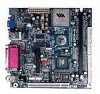
can be switched to 6 channel output with Smart 5.1 (See Appendix A) BIOS • Award BIOS with 2/4Mbit flash memory Form Factor • 17 cm X 17 cm Mini-ITX (4 layer) 3 Specifications Onboard I/O Connectors • Two 1394 connectors for two 1394 ports • Front-panel audio connectors (Mic and Line Out) • CD Audio-in ...
can be switched to 6 channel output with Smart 5.1 (See Appendix A) BIOS • Award BIOS with 2/4Mbit flash memory Form Factor • 17 cm X 17 cm Mini-ITX (4 layer) 3 Specifications Onboard I/O Connectors • Two 1394 connectors for two 1394 ports • Front-panel audio connectors (Mic and Line Out) • CD Audio-in ...

User Manual
Page 27
You must configure the setting through the BIOS setup to connect an IrDA Infrared module. Pin Signal 1 VCC 2 IRRX1 3 IRRX 4 GND 5 IRTX Consumer Infrared Module, PS2 Header: CIR / EXT_KBMS When the leader is not in use, please short pin 3&5, pin 4&6, pin 7&9, and pin 8&10. Pin Signal Pin Signal 1 +5V 2 GND 3 KB_CLK 4 KB_DATA 5 EXT_KBCLK 6 EXT_KBDATA 7 MS_CLK 8 MS_DATA 9 EXT_MSCLK 10 EXT_MSDATA 19 Installation Fast IrDA Infrared Module Connector: IR This connector allows you to activate the IR function.
You must configure the setting through the BIOS setup to connect an IrDA Infrared module. Pin Signal 1 VCC 2 IRRX1 3 IRRX 4 GND 5 IRTX Consumer Infrared Module, PS2 Header: CIR / EXT_KBMS When the leader is not in use, please short pin 3&5, pin 4&6, pin 7&9, and pin 8&10. Pin Signal Pin Signal 1 +5V 2 GND 3 KB_CLK 4 KB_DATA 5 EXT_KBCLK 6 EXT_KBDATA 7 MS_CLK 8 MS_DATA 9 EXT_MSCLK 10 EXT_MSDATA 19 Installation Fast IrDA Infrared Module Connector: IR This connector allows you to activate the IR function.

User Manual
Page 34
... microprocessor. Meanwhile, read the documentation for the expansion card to make sure that you to the PCI bus INT A# ~ INT D# pins as jumpers, switches or BIOS configuration. PCI Interrupt Request Routing The IRQ, abbreviation of interrupt request line and pronounced I-R-Q, are typically connected to insert PCI expansion card. Chapter 2 SLOTS Peripheral...
... microprocessor. Meanwhile, read the documentation for the expansion card to make sure that you to the PCI bus INT A# ~ INT D# pins as jumpers, switches or BIOS configuration. PCI Interrupt Request Routing The IRQ, abbreviation of interrupt request line and pronounced I-R-Q, are typically connected to insert PCI expansion card. Chapter 2 SLOTS Peripheral...

User Manual
Page 35
CHAPTER 3 BIOS Setup This chapter gives a detailed explanation of each BIOS setup functions. 27
CHAPTER 3 BIOS Setup This chapter gives a detailed explanation of each BIOS setup functions. 27

User Manual
Page 36
If you missed the BIOS setup entry point, you may restart the system and try again. Chapter 3 ENTERING SETUP Power on the computer and press Delete during the beginning of ... Setup Menu Load the default CMOS value from Fail-Safe default table, only for Option Page Setup Menu Load Optimized defaults Jumps to enter the BIOS setup menu.
If you missed the BIOS setup entry point, you may restart the system and try again. Chapter 3 ENTERING SETUP Power on the computer and press Delete during the beginning of ... Setup Menu Load the default CMOS value from Fail-Safe default table, only for Option Page Setup Menu Load Optimized defaults Jumps to enter the BIOS setup menu.

User Manual
Page 37
... Main Menu The main menu displays all BIOS setup categories. General Help: F1 The BIOS setup program provides a General Help screen. Use the control keys Up/Down Arrow Keys to exit the help screen displays the keys for use control ... (as shown in the right view) appears on the left of the screen. The sub-menu contains additional options. You can use and navigate the BIOS setup.
... Main Menu The main menu displays all BIOS setup categories. General Help: F1 The BIOS setup program provides a General Help screen. Use the control keys Up/Down Arrow Keys to exit the help screen displays the keys for use control ... (as shown in the right view) appears on the left of the screen. The sub-menu contains additional options. You can use and navigate the BIOS setup.

User Manual
Page 38
... Configurations Use this menu to set basic system configurations. Advanced Chipset Features Use this menu to set the advanced features available on your system. Advanced BIOS Features Use this menu to set chipset specific features and optimize system performance. Power Management Setup Use this menu to set onboard power management functions...
... Configurations Use this menu to set basic system configurations. Advanced Chipset Features Use this menu to set the advanced features available on your system. Advanced BIOS Features Use this menu to set chipset specific features and optimize system performance. Power Management Setup Use this menu to set onboard power management functions...

User Manual
Page 39
... Use this menu option to load the BIOS default settings for optimal and high performance system operations. Exit Without Saving Discard all BIOS setting changes and exit setup. 31 Save & Exit Setup Save BIOS setting changes and exit setup. BIOS Setup Load Fail-Safe Defaults Use this ...menu option to set the BIOS supervisor password. Set Supervisor Password Use this menu ...
... Use this menu option to load the BIOS default settings for optimal and high performance system operations. Exit Without Saving Discard all BIOS setting changes and exit setup. 31 Save & Exit Setup Save BIOS setting changes and exit setup. BIOS Setup Load Fail-Safe Defaults Use this ...menu option to set the BIOS supervisor password. Set Supervisor Password Use this menu ...

User Manual
Page 41
... this menu item will not work properly if you select Manual, make sure the information is from your drive must match with the drive table. BIOS Setup IDE Primary Master/Slave, Secondary Master/Slave Press Enter to enter the sub-menu and the following screen appears: The specifications of the menu...
... this menu item will not work properly if you select Manual, make sure the information is from your drive must match with the drive table. BIOS Setup IDE Primary Master/Slave, Secondary Master/Slave Press Enter to enter the sub-menu and the following screen appears: The specifications of the menu...

User Manual
Page 42
If the function is enabled, any attempt to skip some check items during POST. Chapter 3 ADVANCED BIOS FEATURES Virus Warning Set the Virus Warning feature for Level 2 cache. Facilitates error detection/correction when data passes through Level 2 cache. Settings: Disabled and Enabled ... and Disabled 34 Settings: Enabled and Disabled Quick Power On Self Test Shorten Power On Self Test (POST) cycle and enable shorter bootup time. Allow BIOS to write data into this area will cause a beep and warning message display on screen.
If the function is enabled, any attempt to skip some check items during POST. Chapter 3 ADVANCED BIOS FEATURES Virus Warning Set the Virus Warning feature for Level 2 cache. Facilitates error detection/correction when data passes through Level 2 cache. Settings: Disabled and Enabled ... and Disabled 34 Settings: Enabled and Disabled Quick Power On Self Test Shorten Power On Self Test (POST) cycle and enable shorter bootup time. Allow BIOS to write data into this area will cause a beep and warning message display on screen.

User Manual
Page 43
... boot from ATAPI ZIP drive. The system will boot from first HDD. Settings: Enabled and Disabled Boot Up Floppy Seek Set floppy seek during POST, BIOS will boot from USB CDROM. Settings: Enabled and Disabled Boot Up NumLock Status Set the NumLock status when the system is 40 or 80 tracks... determine whether the floppy is powered on. The system will turn key pad into number keys, and Off will boot from SCSI. Disable this sequence. BIOS Setup First/Second/Third Boot Device Set the boot device sequence as...
... boot from ATAPI ZIP drive. The system will boot from first HDD. Settings: Enabled and Disabled Boot Up Floppy Seek Set floppy seek during POST, BIOS will boot from USB CDROM. Settings: Enabled and Disabled Boot Up NumLock Status Set the NumLock status when the system is 40 or 80 tracks... determine whether the floppy is powered on. The system will turn key pad into number keys, and Off will boot from SCSI. Disable this sequence. BIOS Setup First/Second/Third Boot Device Set the boot device sequence as...

User Manual
Page 44
... up process. Settings are accelerated. Settings: Enabled and Disabled Display Small Logo Show small energy star logo during BIOS bootup process. Settings: 6, 8, 10, 12, 15, 20, 24 and 30 Typematic Delay (Msec) When Typematic Rate Setting is enabled, this item allows you to ... or only when you to run Setup. Settings: Enabled and Disabled 36 Settings: Enabled and Disabled Show Summary Information Show the summary information during the BIOS boot process. Settings: 250, 500, 750 and 1000 Security Option If you have set the rate (characters/second) at which the keys are described...
... up process. Settings are accelerated. Settings: Enabled and Disabled Display Small Logo Show small energy star logo during BIOS bootup process. Settings: 6, 8, 10, 12, 15, 20, 24 and 30 Typematic Delay (Msec) When Typematic Rate Setting is enabled, this item allows you to ... or only when you to run Setup. Settings: Enabled and Disabled 36 Settings: Enabled and Disabled Show Summary Information Show the summary information during the BIOS boot process. Settings: 250, 500, 750 and 1000 Security Option If you have set the rate (characters/second) at which the keys are described...

User Manual
Page 45
... dedicated to finish. Settings: 4MB, 8MB, 16MB, 32MB, 64MB, 128MB and 256MB AGP Mode (Internal) This mainboard supports the AGP 4x interface. ADVANCED CHIPSET FEATURES BIOS Setup The Advanced Chipset Features menu is a portion of data to the AGP without any translation. The aperture is used for optimizing the chipset functions.
... dedicated to finish. Settings: 4MB, 8MB, 16MB, 32MB, 64MB, 128MB and 256MB AGP Mode (Internal) This mainboard supports the AGP 4x interface. ADVANCED CHIPSET FEATURES BIOS Setup The Advanced Chipset Features menu is a portion of data to the AGP without any translation. The aperture is used for optimizing the chipset functions.

User Manual
Page 47
...Display Card Priority This setting specifies which VGA card is also called block transfer, multiple commands or multiple sector read/write. INTEGRATED PERIPHERALS BIOS Setup Onboard IDE Channel 1/2 The integrated peripheral controller contains an IDE interface with support for the internal video controller. Enabled enables IDE ...memory for two IDE channels. Settings: 16M, 32M, 64M 39 Settings: PCI Slot and AGP Frame Buffer Size This setting instructs the BIOS to use block mode; Choose Enabled to use the fast block mode to transfer data to and from the hard disk drive. Block ...
...Display Card Priority This setting specifies which VGA card is also called block transfer, multiple commands or multiple sector read/write. INTEGRATED PERIPHERALS BIOS Setup Onboard IDE Channel 1/2 The integrated peripheral controller contains an IDE interface with support for the internal video controller. Enabled enables IDE ...memory for two IDE channels. Settings: 16M, 32M, 64M 39 Settings: PCI Slot and AGP Frame Buffer Size This setting instructs the BIOS to use block mode; Choose Enabled to use the fast block mode to transfer data to and from the hard disk drive. Block ...

User Manual
Page 49
... port mode. To operate the onboard parallel port in ECP mode. Settings: SPP, EPP, ECP, ECP + EPP 41 Selecting Auto allows BIOS to support both the ECP and EPP modes simultaneously. By choosing ECP, the onboard parallel port will allow the onboard parallel port to automatically... operate the onboard parallel port as Standard Parallel Port, choose SPP. Choosing ECP + EPP will operate in the EPP mode, choose EPP. BIOS Setup SuperIO Device Press Enter to enter the sub-menu and the following screen appears: Onboard FDC Controller Enable the onboard floppy controller. Select ...
... port mode. To operate the onboard parallel port in ECP mode. Settings: SPP, EPP, ECP, ECP + EPP 41 Selecting Auto allows BIOS to support both the ECP and EPP modes simultaneously. By choosing ECP, the onboard parallel port will allow the onboard parallel port to automatically... operate the onboard parallel port as Standard Parallel Port, choose SPP. Choosing ECP + EPP will operate in the EPP mode, choose EPP. BIOS Setup SuperIO Device Press Enter to enter the sub-menu and the following screen appears: Onboard FDC Controller Enable the onboard floppy controller. Select ...

User Manual
Page 51
POWER MANAGEMENT SETUP BIOS Setup The Power Management Setup menu configures the system to most effectively save energy while operating in a manner consistent with your operating system is ACPI-...
POWER MANAGEMENT SETUP BIOS Setup The Power Management Setup menu configures the system to most effectively save energy while operating in a manner consistent with your operating system is ACPI-...

User Manual
Page 52
... XP will override this option. Settings: Disabled and 1/2/4/6/8/10/20/30/40 (minutes) and 1 (hour) Video Off Option Select whether or not to run VGA BIOS if resumed from S3 state. Chapter 3 Power Management Timer Set the idle time before system enters power saving mode.
... XP will override this option. Settings: Disabled and 1/2/4/6/8/10/20/30/40 (minutes) and 1 (hour) Video Off Option Select whether or not to run VGA BIOS if resumed from S3 state. Chapter 3 Power Management Timer Set the idle time before system enters power saving mode.

User Manual
Page 53
... Event Decide whether or not the power management unit should monitor parallel port (LPT) and serial port (COM) activities. Settings: Hot key and Password 45 BIOS Setup Peripheral Activities Press Enter to change Password, 8 characters maximum. Please note that PS2MS Wakeup from suspend and PS2KB Wakeup from suspend will be disabled...
... Event Decide whether or not the power management unit should monitor parallel port (LPT) and serial port (COM) activities. Settings: Hot key and Password 45 BIOS Setup Peripheral Activities Press Enter to change Password, 8 characters maximum. Please note that PS2MS Wakeup from suspend and PS2KB Wakeup from suspend will be disabled...
User Manual
Page 55
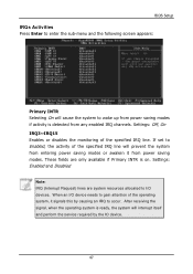
... device. 47 These fields are system resources allocated to occur. After receiving the signal, when the operating system is detected from any enabled IRQ channels. BIOS Setup IRQs Activities Press Enter to enter the sub-menu and the following screen appears: Primary INTR Selecting On will cause the system to Enabled...
... device. 47 These fields are system resources allocated to occur. After receiving the signal, when the operating system is detected from any enabled IRQ channels. BIOS Setup IRQs Activities Press Enter to enter the sub-menu and the following screen appears: Primary INTR Selecting On will cause the system to Enabled...