
User Manual
Page 1
User's Manual EPIA-M Mini-ITX Mainboard P/N: 99-51-012561-14 Version 1.52 January 30, 2012
User's Manual EPIA-M Mini-ITX Mainboard P/N: 99-51-012561-14 Version 1.52 January 30, 2012
User Manual
Page 6
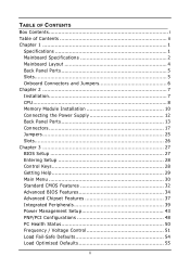
TABLE OF CONTENTS Box Contents i Table of Contents ii Chapter 1 1 Specifications 1 Mainboard Specifications 2 Mainboard Layout 4 Back Panel Ports 5 Slots 5 Onboard Connectors and Jumpers 6 Chapter 2 7 Installation 7 CPU 8 Memory Module Installation 10 Connecting the Power Supply 12 Back Panel Ports 13 ...
TABLE OF CONTENTS Box Contents i Table of Contents ii Chapter 1 1 Specifications 1 Mainboard Specifications 2 Mainboard Layout 4 Back Panel Ports 5 Slots 5 Onboard Connectors and Jumpers 6 Chapter 2 7 Installation 7 CPU 8 Memory Module Installation 10 Connecting the Power Supply 12 Back Panel Ports 13 ...

User Manual
Page 9
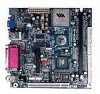
CHAPTER 1 Specifications The ultra-compact and highly integrated VIA EPIA-M Mini-ITX Mainboard is the smallest form factor mainboard specification available today, developed by VIA Technologies, Inc. The mainboard enables the creation of an exciting new generation of small, ergonomic, innovative and affordable embedded systems. Through high level of integration, mini-ITX only occupy 66% of the size of the company...
CHAPTER 1 Specifications The ultra-compact and highly integrated VIA EPIA-M Mini-ITX Mainboard is the smallest form factor mainboard specification available today, developed by VIA Technologies, Inc. The mainboard enables the creation of an exciting new generation of small, ergonomic, innovative and affordable embedded systems. Through high level of integration, mini-ITX only occupy 66% of the size of the company...
User Manual
Page 10
... operations with MPEG-2 accelerator Audio • VT1616 six channel AC'97 Codec • 3 Audio jacks: Line-in, Line-out and Mic-in; Chapter 1 MAINBOARD SPECIFICATIONS CPU • • • VIA C3 / EDEN EBGA Processor (on board) Enhanced Ball Grid Array Package (EBGA) Internal L1 128KB and L2 64KB cache memory Chipset •...
... operations with MPEG-2 accelerator Audio • VT1616 six channel AC'97 Codec • 3 Audio jacks: Line-in, Line-out and Mic-in; Chapter 1 MAINBOARD SPECIFICATIONS CPU • • • VIA C3 / EDEN EBGA Processor (on board) Enhanced Ball Grid Array Package (EBGA) Internal L1 128KB and L2 64KB cache memory Chipset •...
User Manual
Page 15
Static electricity can damage some components. 7 It is recommended to use a grounded wrist strap before handling computer components. Some components may be damaged if they are installed incorrectly. CHAPTER 2 Installation This chapter provides you with information about hardware setup procedures. While installing the mainboard, carefully hold the components and closely follow the installation procedures.
Static electricity can damage some components. 7 It is recommended to use a grounded wrist strap before handling computer components. Some components may be damaged if they are installed incorrectly. CHAPTER 2 Installation This chapter provides you with information about hardware setup procedures. While installing the mainboard, carefully hold the components and closely follow the installation procedures.

User Manual
Page 16
...correctly installed as shown. 8 Ensure that the red wire is an additional FAN connector. Chapter 2 CPU The VIA EPIA-M Mini-ITX Mainboard includes an embedded VIA Eden Processor or VIA C3 E-Series Processor. Both CPU and System fan connectors have sensors to guarantee performance and reliability. When connecting...connectors, always be connected to the +12V. SYSFAN CPUFAN Sensor +12V GND FAN3 The VIA C3 E-Series Processor With low power consumption and advanced thermal dissipation properties, the embedded VIA C3 E-Series requires only a small fan to detect fan speed, but the power ...
...correctly installed as shown. 8 Ensure that the red wire is an additional FAN connector. Chapter 2 CPU The VIA EPIA-M Mini-ITX Mainboard includes an embedded VIA Eden Processor or VIA C3 E-Series Processor. Both CPU and System fan connectors have sensors to guarantee performance and reliability. When connecting...connectors, always be connected to the +12V. SYSFAN CPUFAN Sensor +12V GND FAN3 The VIA C3 E-Series Processor With low power consumption and advanced thermal dissipation properties, the embedded VIA C3 E-Series requires only a small fan to detect fan speed, but the power ...
User Manual
Page 18
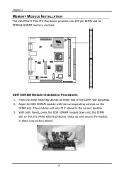
Align the DDR SDRAM module with the corresponding notches on the DIMM slot. DDR SDRAM Module Installation Procedures 1. The modules will only fit if placed in place (see picture below). 10 With both hands, press the DDR SDRAM module down into the DIMM slot so that the white retaining latches rotate up and secure the module in the correct position. 3. Push the white retaining latches at either end of the DIMM slot outwards. 2. Chapter 2 MEMORY MODULE INSTALLATION The VIA EPIA-M Mini-ITX Mainboard provides one 184-pin DIMM slot for DDR266 SDRAM memory modules.
Align the DDR SDRAM module with the corresponding notches on the DIMM slot. DDR SDRAM Module Installation Procedures 1. The modules will only fit if placed in place (see picture below). 10 With both hands, press the DDR SDRAM module down into the DIMM slot so that the white retaining latches rotate up and secure the module in the correct position. 3. Push the white retaining latches at either end of the DIMM slot outwards. 2. Chapter 2 MEMORY MODULE INSTALLATION The VIA EPIA-M Mini-ITX Mainboard provides one 184-pin DIMM slot for DDR266 SDRAM memory modules.
User Manual
Page 19
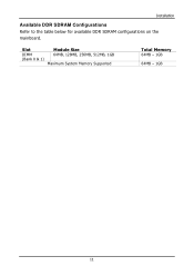
Slot DIMM (Bank 0 & 1) Module Size 64MB, 128MB, 256MB, 512MB, 1GB Maximum System Memory Supported Total Memory 64MB - 1GB 64MB - 1GB 11 Installation Available DDR SDRAM Configurations Refer to the table below for available DDR SDRAM configurations on the mainboard.
Slot DIMM (Bank 0 & 1) Module Size 64MB, 128MB, 256MB, 512MB, 1GB Maximum System Memory Supported Total Memory 64MB - 1GB 64MB - 1GB 11 Installation Available DDR SDRAM Configurations Refer to the table below for available DDR SDRAM configurations on the mainboard.

User Manual
Page 20
... 12 -12V 13 GND 14 PS_ON 15 GND 16 GND 17 GND 18 NC 19 5V 20 5V 12 Chapter 2 CONNECTING THE POWER SUPPLY The VIA EPIA-M Mini-ITX Mainboard requires an ATX power supply to ensure that no damage will be connected. Before inserting the power supply connector, always make sure the power plug...
... 12 -12V 13 GND 14 PS_ON 15 GND 16 GND 17 GND 18 NC 19 5V 20 5V 12 Chapter 2 CONNECTING THE POWER SUPPLY The VIA EPIA-M Mini-ITX Mainboard requires an ATX power supply to ensure that no damage will be connected. Before inserting the power supply connector, always make sure the power plug...
User Manual
Page 21
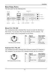
...) Pin Signal 1 Mouse DATA 2 NC 3 GND 4 VCC 5 Mouse Clock 6 NC Description Mouse data No connection Ground +5V Mouse clock No connection Keyboard Port: PS2_KB The mainboard provides a standard PS/2 keyboard connector for attaching a PS/2 mouse. BACK PANEL PORTS The back panel has the following ports: PS2_MS RJ45 Parallel (LPT1) PS2_KB VGA...
...) Pin Signal 1 Mouse DATA 2 NC 3 GND 4 VCC 5 Mouse Clock 6 NC Description Mouse data No connection Ground +5V Mouse clock No connection Keyboard Port: PS2_KB The mainboard provides a standard PS/2 keyboard connector for attaching a PS/2 mouse. BACK PANEL PORTS The back panel has the following ports: PS2_MS RJ45 Parallel (LPT1) PS2_KB VGA...

User Manual
Page 22
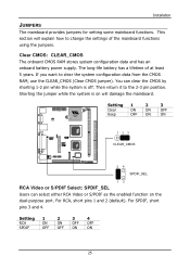
...section for connection to a VGA monitor. Chapter 2 VGA Out A DB-15 pin female connector that connects to the Local Area Network (LAN). USB Ports The mainboard provides 2 USB 2.0 ports. See SPDIF_SEL in NTSC and PAL modes. Pin Signal 1 VCC 2 -DATA 3 +DATA 4 GND Description +5V Negative data ...channel Positive data channel Ground 1 234 RJ45 10/100 NIC Port The mainboard provides one standard RJ-45 port for more details. 14 RCA Video or S/PDIF Port This dual function port may be plugged directly into these...
...section for connection to a VGA monitor. Chapter 2 VGA Out A DB-15 pin female connector that connects to the Local Area Network (LAN). USB Ports The mainboard provides 2 USB 2.0 ports. See SPDIF_SEL in NTSC and PAL modes. Pin Signal 1 VCC 2 -DATA 3 +DATA 4 GND Description +5V Negative data ...channel Positive data channel Ground 1 234 RJ45 10/100 NIC Port The mainboard provides one standard RJ-45 port for more details. 14 RCA Video or S/PDIF Port This dual function port may be plugged directly into these...
User Manual
Page 23
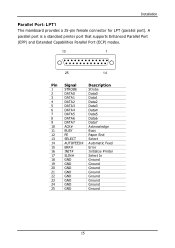
Installation Parallel Port: LPT1 The mainboard provides a 25-pin female connector for LPT (parallel port). A parallel port is a standard printer port that supports Enhanced Parallel Port (EPP) and Extended Capabilities Parallel ...
Installation Parallel Port: LPT1 The mainboard provides a 25-pin female connector for LPT (parallel port). A parallel port is a standard printer port that supports Enhanced Parallel Port (EPP) and Extended Capabilities Parallel ...
User Manual
Page 24
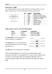
... with Smart 5.1 (See Appendix A) In order for connecting to function, the operating system and multimedia application must be properly configured. Chapter 2 Serial Ports: COM1 The mainboard offers two 9-pin male Serial Port connectors COM1. Please note that Windows 98 only supports 4-channel audio. 16 The Line-In jack is for connecting...
... with Smart 5.1 (See Appendix A) In order for connecting to function, the operating system and multimedia application must be properly configured. Chapter 2 Serial Ports: COM1 The mainboard offers two 9-pin male Serial Port connectors COM1. Please note that Windows 98 only supports 4-channel audio. 16 The Line-In jack is for connecting...
User Manual
Page 25
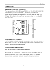
... disk drive, CDROM, LS-120 and other devices. These connectors utilize the provided IDE hard disk cable. CONNECTORS Installation Hard Disk Connectors: IDE1 & IDE2 The mainboard has a 32-bit Enhanced PCI IDE and Ultra DMA 33/66/100/133 controller that provides PIO mode 0~4, Bus Master, and Ultra DMA 33/66...
... disk drive, CDROM, LS-120 and other devices. These connectors utilize the provided IDE hard disk cable. CONNECTORS Installation Hard Disk Connectors: IDE1 & IDE2 The mainboard has a 32-bit Enhanced PCI IDE and Ultra DMA 33/66/100/133 controller that provides PIO mode 0~4, Bus Master, and Ultra DMA 33/66...
User Manual
Page 28
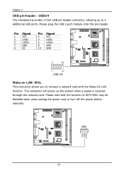
... cord or turn off the power button manually. 20 Please plug the USB 2-port module onto this pin-header. Chapter 2 USB pin-header: USB3/4 The mainboard provides 1 front USB pin-header connector, allowing up the system when a signal is received through the network card.
... cord or turn off the power button manually. 20 Please plug the USB 2-port module onto this pin-header. Chapter 2 USB pin-header: USB3/4 The mainboard provides 1 front USB pin-header connector, allowing up the system when a signal is received through the network card.
User Manual
Page 31
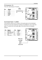
Pin Signal 1 +3.3V 2 +3.3V 3 EL-ON 4 SMBCK 5 SMBDT 6 GND Installation Front Audio Panel: F_AUDIO This connector allows you to connect a front audio panel to the mainboard. Only the line-out and microphone functions are available for connecting an I ²C This is for use on the front panel. To connect the front audio cable, first remove the two red plastic jumpers. Pin Signal Pin 1 FRN_MIC 2 3 AUD_MIC_BIAS 4 5 LINE_OUT_R 6 7 NC 8 9 LINE_OUT_L 10 Signal AGND +5V Next_R Key pin Next_L 23 I²C Connector: I ²C device.
Pin Signal 1 +3.3V 2 +3.3V 3 EL-ON 4 SMBCK 5 SMBDT 6 GND Installation Front Audio Panel: F_AUDIO This connector allows you to connect a front audio panel to the mainboard. Only the line-out and microphone functions are available for connecting an I ²C This is for use on the front panel. To connect the front audio cable, first remove the two red plastic jumpers. Pin Signal Pin 1 FRN_MIC 2 3 AUD_MIC_BIAS 4 5 LINE_OUT_R 6 7 NC 8 9 LINE_OUT_L 10 Signal AGND +5V Next_R Key pin Next_L 23 I²C Connector: I ²C device.
User Manual
Page 32
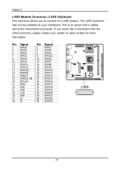
... 30 GFPD18 32 GFPD19 34 GFPD20 36 GFPD21 38 GFPD22 40 GFPD23 24 Chapter 2 LVDS Module Connector: LVDS (Optional) This connector allows you would like a mainboard with the LVDS connector, please contact your mainboard. If you to connect to a LVDS module.
... 30 GFPD18 32 GFPD19 34 GFPD20 36 GFPD21 38 GFPD22 40 GFPD23 24 Chapter 2 LVDS Module Connector: LVDS (Optional) This connector allows you would like a mainboard with the LVDS connector, please contact your mainboard. If you to connect to a LVDS module.
User Manual
Page 33
... it to clear the system configuration data from the CMOS RAM, use the CLEAR_CMOS (Clear CMOS jumper). Installation JUMPERS The mainboard provides jumpers for setting some mainboard functions. This section will damage the mainboard. Clear CMOS: CLEAR_CMOS The onboard CMOS RAM stores system configuration data and has an onboard battery power supply. The...
... it to clear the system configuration data from the CMOS RAM, use the CLEAR_CMOS (Clear CMOS jumper). Installation JUMPERS The mainboard provides jumpers for setting some mainboard functions. This section will damage the mainboard. Clear CMOS: CLEAR_CMOS The onboard CMOS RAM stores system configuration data and has an onboard battery power supply. The...

User Manual
Page 45
... to four words of the PCI memory address range dedicated to finish. Settings: 4MB, 8MB, 16MB, 32MB, 64MB, 128MB and 256MB AGP Mode (Internal) This mainboard supports the AGP 4x interface. Settings: Enabled and Disabled 37 ADVANCED CHIPSET FEATURES BIOS Setup The Advanced Chipset Features menu is used for video purposes...
... to four words of the PCI memory address range dedicated to finish. Settings: 4MB, 8MB, 16MB, 32MB, 64MB, 128MB and 256MB AGP Mode (Internal) This mainboard supports the AGP 4x interface. Settings: Enabled and Disabled 37 ADVANCED CHIPSET FEATURES BIOS Setup The Advanced Chipset Features menu is used for video purposes...

User Manual
Page 48
...This field is only available if Onboard Fast IR is disabled. Settings: Auto and Disabled MC97 Modem Auto allows the mainboard to detect whether a modem is used . Settings: Auto and Disabled VIA OnChip LAN This setting allows you want to use other controller cards to connect to a modem. Settings: 3, ... will be enabled; if not, it is enabled. Settings: 6, 5 40 otherwise, it is enabled. Chapter 3 AC'97 Audio Auto allows the mainboard to detect whether an audio device is used . This field is only available if Onboard Fast IR is disabled. If the device is detected, the...
...This field is only available if Onboard Fast IR is disabled. Settings: Auto and Disabled MC97 Modem Auto allows the mainboard to detect whether a modem is used . Settings: Auto and Disabled VIA OnChip LAN This setting allows you want to use other controller cards to connect to a modem. Settings: 3, ... will be enabled; if not, it is enabled. Settings: 6, 5 40 otherwise, it is enabled. Chapter 3 AC'97 Audio Auto allows the mainboard to detect whether an audio device is used . This field is only available if Onboard Fast IR is disabled. If the device is detected, the...