
User Manual
Page 8
... CMOS Jumper: CLEAR_CMOS 2-15 Host Frequency Select (J13 2-16 Auto Reboot Function Setting (J2 2-17 RCA Video or S/PDIF Select (J11 2-17 Slots 2-18 PCI Slots 2-18 PCI Interrupt Request Routing 2-19 BIOS Setup 3-1 Entering Setup 3-2 Control Keys 3-2 Getting Help ...3-3 The Main Menu 3-4 Standard CMOS Features 3-6 Advanced BIOS Features 3-8 Advanced Chipset Features 3-11 Integrated Peripherals 3-13 Power Management Setup 3-16 PNP/PCI Configurations 3-21 PC Health Status...
... CMOS Jumper: CLEAR_CMOS 2-15 Host Frequency Select (J13 2-16 Auto Reboot Function Setting (J2 2-17 RCA Video or S/PDIF Select (J11 2-17 Slots 2-18 PCI Slots 2-18 PCI Interrupt Request Routing 2-19 BIOS Setup 3-1 Entering Setup 3-2 Control Keys 3-2 Getting Help ...3-3 The Main Menu 3-4 Standard CMOS Features 3-6 Advanced BIOS Features 3-8 Advanced Chipset Features 3-11 Integrated Peripherals 3-13 Power Management Setup 3-16 PNP/PCI Configurations 3-21 PC Health Status...

User Manual
Page 12
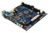
... • 1 VGA port • 1 RCA port (S/PDIF or TV out) • 1 S-Video port Power • Supports ATX type power supply Onboard Floppy • 1 FDD connector BIOS • Award BIOS • 2/4Mbit flash memory Form Factor • Mini-ITX (4 layers) • 17 cm x 17 cm 1-3 Specifications
... • 1 VGA port • 1 RCA port (S/PDIF or TV out) • 1 S-Video port Power • Supports ATX type power supply Onboard Floppy • 1 FDD connector BIOS • Award BIOS • 2/4Mbit flash memory Form Factor • Mini-ITX (4 layers) • 17 cm x 17 cm 1-3 Specifications

User Manual
Page 13
... PS / 2 Keyboard Mouse PS2 Connector J6 South Bridge VT8231 J5 FIR Module Connector North Bridge VT8601A Processor EBGA Clock Generator DIMM 1 J13 Host Frequency Select BIOS ROM FDD IDE 1 DIMM 2 ATX Power Connector VIA EPIA-V Mini-ITX Mainboard 1-4
... PS / 2 Keyboard Mouse PS2 Connector J6 South Bridge VT8231 J5 FIR Module Connector North Bridge VT8601A Processor EBGA Clock Generator DIMM 1 J13 Host Frequency Select BIOS ROM FDD IDE 1 DIMM 2 ATX Power Connector VIA EPIA-V Mini-ITX Mainboard 1-4

User Manual
Page 26
You must configure the setting through the BIOS setup to connect a Fast Infrared standard module. Chapter 2 FIR Module Connector (J5) The FIR Module Connector (J5) allows you to activate the IR function. Pin Definition PIN SIGNAL 1 1 +3V 2 IRRX 3 IRRX2 4 GND 5 IRTX PS2 Connector (J6) When this connector is not in use, please short pin 3&5, pin 4&6, pin 7&9, and pin 8&10. 10 9 2 1 Pin Definition PIN SIGNAL PIN SIGNAL 1 +5V 2 GND 3 KB_CLK 4 KB_DATA 5 EXT_KBCLK 6 EXT_KBDATA 7 MS_CLK 8 MS_DATA 9 EXT_MSCLK 10 EXT_MSDATA 2-12
You must configure the setting through the BIOS setup to connect a Fast Infrared standard module. Chapter 2 FIR Module Connector (J5) The FIR Module Connector (J5) allows you to activate the IR function. Pin Definition PIN SIGNAL 1 1 +3V 2 IRRX 3 IRRX2 4 GND 5 IRTX PS2 Connector (J6) When this connector is not in use, please short pin 3&5, pin 4&6, pin 7&9, and pin 8&10. 10 9 2 1 Pin Definition PIN SIGNAL PIN SIGNAL 1 +5V 2 GND 3 KB_CLK 4 KB_DATA 5 EXT_KBCLK 6 EXT_KBDATA 7 MS_CLK 8 MS_DATA 9 EXT_MSCLK 10 EXT_MSDATA 2-12

User Manual
Page 32
When adding or removing expansion cards, make any necessary hardware or software settings for the expansion card to make sure that you to insert PCI expansion card. Chapter 2 Slots PCI Slot The PCI slot allows you unplug the power supply first. Meanwhile, read the documentation for the expansion card, such as jumpers, switches or BIOS configuration. 2-18
When adding or removing expansion cards, make any necessary hardware or software settings for the expansion card to make sure that you to insert PCI expansion card. Chapter 2 Slots PCI Slot The PCI slot allows you unplug the power supply first. Meanwhile, read the documentation for the expansion card, such as jumpers, switches or BIOS configuration. 2-18

User Manual
Page 34
3 BIOS Setup BIOS Setup This chapter gives you detailed explaination of the following topics: Entering Setup Control Keys Getting Help The Main Menu Standard CMOS Features Advanced BIOS Features Advanced Chipset Features Integrated Peripherals Power Management Setup PNP/PCI Configurations PC Health Status Frequency/Voltage Control Load Fail-Safe Defaults Load Optimized Defaults Set Supervisor/User Password Save & Exit Setup Exit Without Saving 3-2 3-2 3-3 3-4 3-6 3-8 3-11 3-13 3-16 3-21 3-23 3-24 3-25 3-26 3-27 3-29 3-30 3-1 It consists of BIOS setup functions.
3 BIOS Setup BIOS Setup This chapter gives you detailed explaination of the following topics: Entering Setup Control Keys Getting Help The Main Menu Standard CMOS Features Advanced BIOS Features Advanced Chipset Features Integrated Peripherals Power Management Setup PNP/PCI Configurations PC Health Status Frequency/Voltage Control Load Fail-Safe Defaults Load Optimized Defaults Set Supervisor/User Password Save & Exit Setup Exit Without Saving 3-2 3-2 3-3 3-4 3-6 3-8 3-11 3-13 3-16 3-21 3-23 3-24 3-25 3-26 3-27 3-29 3-30 3-1 It consists of BIOS setup functions.

User Manual
Page 35
... hand Move to the item in the right hand Select the item Jumps to the Exit menu or returns to enter the BIOS setup menu. If you missed the BIOS setup entry point, you may restart the system and try again. Chapter 3 Entering Setup Power on the computer and press DEL straight...
... hand Move to the item in the right hand Select the item Jumps to the Exit menu or returns to enter the BIOS setup menu. If you missed the BIOS setup entry point, you may restart the system and try again. Chapter 3 Entering Setup Power on the computer and press DEL straight...

User Manual
Page 36
... categories. The sub-menu contains additional options. You can use and navigate the BIOS setup. To return from any item/sub-menu. Press to enter the sub-menu. Description of the selected/highlighted category is displayed at the bottom ... screen displays the keys for use control keys (LK) to highlight the field and press to exit the help screen. 3-3 Getting Help After entering the BIOS setup menu, the Main Menu appears. IDE Primary Master IDE Primary Slave IDE Secondary Master IDE Secondary Slave General Help The...
... categories. The sub-menu contains additional options. You can use and navigate the BIOS setup. To return from any item/sub-menu. Press to enter the sub-menu. Description of the selected/highlighted category is displayed at the bottom ... screen displays the keys for use control keys (LK) to highlight the field and press to exit the help screen. 3-3 Getting Help After entering the BIOS setup menu, the Main Menu appears. IDE Primary Master IDE Primary Slave IDE Secondary Master IDE Secondary Slave General Help The...

User Manual
Page 37
Advanced BIOS Features Use this menu to set chipset specific features and optimize system performance. PnP/PCI Configurations Use this menu to set the PnP and PCI ...
Advanced BIOS Features Use this menu to set chipset specific features and optimize system performance. PnP/PCI Configurations Use this menu to set the PnP and PCI ...

User Manual
Page 38
...set supervisor password. Set Supervisor Password Use this menu to load the BIOS default settings for optimal and high performance system operations. Exit Without Saving Abandon all BIOS setting changes and exit setup. 3-5 Save & Exit Setup Save BIOS setting changes and exit setup. Load Optimized Defaults Use this menu ... voltage control. Load Fail-Safe Defaults Use this menu to set user password. Frequency/Voltage Control Use this menu to load BIOS default settings for minimal and stable system operations. BIOS Setup PC Health Status This menu shows the PC health status.
...set supervisor password. Set Supervisor Password Use this menu to load the BIOS default settings for optimal and high performance system operations. Exit Without Saving Abandon all BIOS setting changes and exit setup. 3-5 Save & Exit Setup Save BIOS setting changes and exit setup. Load Optimized Defaults Use this menu ... voltage control. Load Fail-Safe Defaults Use this menu to set user password. Frequency/Voltage Control Use this menu to load BIOS default settings for minimal and stable system operations. BIOS Setup PC Health Status This menu shows the PC health status.
User Manual
Page 40
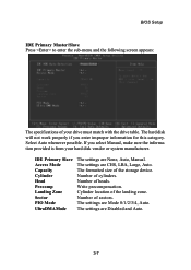
The settings are None, Auto, Manual. Number of heads. BIOS Setup IDE Primary Master/Slave Press to enter the sub-menu and the following screen appears: The specifications of your hard disk vendor or system ...
The settings are None, Auto, Manual. Number of heads. BIOS Setup IDE Primary Master/Slave Press to enter the sub-menu and the following screen appears: The specifications of your hard disk vendor or system ...

User Manual
Page 41
... any attempt to skip some check items during POST. Settings: Disabled and Enabled. Settings: Enabled and Disabled. Settings: Enabled and Disabled. Allow BIOS to write data into this area will cause a beep and a warning message will be displayed. Settings: Enabled and Disabled. Quick Power On ...On Self Test (POST) cycle and enable shorter bootup time. Facilitates error detection/correction when data passes through Level 2 cache. Chapter 3 Advanced BIOS Features Virus Warning Set the Virus Warning feature for Level 2 cache. The settings are: 3-8 CPU L2 Cache ECC Checking Set the ECC (...
... any attempt to skip some check items during POST. Settings: Disabled and Enabled. Settings: Enabled and Disabled. Settings: Enabled and Disabled. Allow BIOS to write data into this area will cause a beep and a warning message will be displayed. Settings: Enabled and Disabled. Quick Power On ...On Self Test (POST) cycle and enable shorter bootup time. Facilitates error detection/correction when data passes through Level 2 cache. Chapter 3 Advanced BIOS Features Virus Warning Set the Virus Warning feature for Level 2 cache. The settings are: 3-8 CPU L2 Cache ECC Checking Set the ECC (...

User Manual
Page 42
... boot from other devices if the system fails to control Gate A20, and the Nomal option makes a pin in the keyboard controller control Gate A20. BIOS Setup Floppy LS120 HDD-0 SCSI CD-ROM HDD-1 HDD-2 HDD-3 ZIP100 USB-FDD USB-ZIP USB-CDROM USB-HDD LAN Disabled The system will boot... system will determine whether the floppy is powered on. Disable this sequence. Settings: Enabled and Disabled. Boot Up Floppy Seek Set floppy seek during POST, BIOS will boot from USB HDD. The system will turn key pad into arrow keys.
... boot from other devices if the system fails to control Gate A20, and the Nomal option makes a pin in the keyboard controller control Gate A20. BIOS Setup Floppy LS120 HDD-0 SCSI CD-ROM HDD-1 HDD-2 HDD-3 ZIP100 USB-FDD USB-ZIP USB-CDROM USB-HDD LAN Disabled The system will boot... system will determine whether the floppy is powered on. Disable this sequence. Settings: Enabled and Disabled. Boot Up Floppy Seek Set floppy seek during POST, BIOS will boot from USB HDD. The system will turn key pad into arrow keys.

User Manual
Page 43
...Setting Set the typematic rate and delay. Settings: 6, 8, 10, 12, 15, 20, 24 and 30. Security Option Specifies the type of BIOS password protection that is enabled. Settings: Enabled and Disabled. Settings: Enabled and Disabled. This item allows you to run Setup. Settings are accelerated. .... Settings: 250, 500, 750 and 1000. Settings: Enabled and Disabled. 3-10 Display Full Screen logo Show full screen logo during BIOS bootup process. This item allows you to run Setup. System A password prompt appears every time when the computer is enabled. Show Summary...
...Setting Set the typematic rate and delay. Settings: 6, 8, 10, 12, 15, 20, 24 and 30. Security Option Specifies the type of BIOS password protection that is enabled. Settings: Enabled and Disabled. Settings: Enabled and Disabled. This item allows you to run Setup. Settings are accelerated. .... Settings: 250, 500, 750 and 1000. Settings: Enabled and Disabled. 3-10 Display Full Screen logo Show full screen logo during BIOS bootup process. This item allows you to run Setup. System A password prompt appears every time when the computer is enabled. Show Summary...

User Manual
Page 44
... without any translation. Host cycles that hit the aperture range are familiar with the chipset. CPU & PCI Bus Control Press to graphics memory address space. BIOS Setup Advanced Chipset Features The Advanced Chipset Features menu is a portion of the PCI memory address range dedicated to enter the sub-menu and the...
... without any translation. Host cycles that hit the aperture range are familiar with the chipset. CPU & PCI Bus Control Press to graphics memory address space. BIOS Setup Advanced Chipset Features The Advanced Chipset Features menu is a portion of the PCI memory address range dedicated to enter the sub-menu and the...

User Manual
Page 46
... mode; Enabled enables IDE controller to activate the channel. Frame Buffer Size Set the Frame Buffer size. Choose Enabled to use standard mode. Integrated Peripherals BIOS Setup Onboard IDE Channel The integrated peripheral controller contains an IDE interface.
... mode; Enabled enables IDE controller to activate the channel. Frame Buffer Size Set the Frame Buffer size. Choose Enabled to use standard mode. Integrated Peripherals BIOS Setup Onboard IDE Channel The integrated peripheral controller contains an IDE interface.

User Manual
Page 48
Onboard FIR Select Enable onboard fast IR functions. Selecting Auto allows BIOS to enter the sub-menu and the following screen appears: Onboard FDD Controller Enable the onboard floppy controller. Settings: 378/IRQ7, 278/IRQ5, 3BC/IRQ7 ..., 2F8/IRQ3, 3E8/ IRQ4, 2E8/IRQ3 and Auto. Onboard Parallel Port This specifies the I /O port address. Settings: IRQ3, IRQ 9, IRQ 10 and Disabled. 3-15 BIOS Setup VIA SuperIO Device Press to automatically determine the correct base I /O port address and IRQ of the onboard parallel port. Onboard Serial Port 1 Set the base I/O port...
Onboard FIR Select Enable onboard fast IR functions. Selecting Auto allows BIOS to enter the sub-menu and the following screen appears: Onboard FDD Controller Enable the onboard floppy controller. Settings: 378/IRQ7, 278/IRQ5, 3BC/IRQ7 ..., 2F8/IRQ3, 3E8/ IRQ4, 2E8/IRQ3 and Auto. Onboard Parallel Port This specifies the I /O port address. Settings: IRQ3, IRQ 9, IRQ 10 and Disabled. 3-15 BIOS Setup VIA SuperIO Device Press to automatically determine the correct base I /O port address and IRQ of the onboard parallel port. Onboard Serial Port 1 Set the base I/O port...

User Manual
Page 50
... is saved to main memory, and context is a low power state. Settings are : Delay 4 Sec - The screen is turned off button. Settings are : Always On - BIOS Setup Set the idle time before system enters power saving mode. Settings are: S1/POS - Suspend -> Off - The system is pressed for ACPI function. AC...
... is saved to main memory, and context is a low power state. Settings are : Delay 4 Sec - The screen is turned off button. Settings are : Always On - BIOS Setup Set the idle time before system enters power saving mode. Settings are: S1/POS - Suspend -> Off - The system is pressed for ACPI function. AC...

User Manual
Page 52
... Decide whether or not Ring-In signals from Modem can wake the system from power saving mode. Settings: Disabled and Enabled. Settings: Disabled and Enabled. BIOS Setup PS2KB Wakeup from suspend Select which "Hot-Key" is used to wake-up the system on a scheduled time/date. Format is . 3-19 Settings: Disabled...
... Decide whether or not Ring-In signals from Modem can wake the system from power saving mode. Settings: Disabled and Enabled. Settings: Disabled and Enabled. BIOS Setup PS2KB Wakeup from suspend Select which "Hot-Key" is used to wake-up the system on a scheduled time/date. Format is . 3-19 Settings: Disabled...
User Manual
Page 54
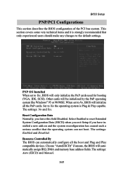
... When set to reset Extended System Configuration Data (ESCD) when you exit Setup if you leave this field Disabled. Select Enabled to Yes, BIOS will initialize all the boot and Plug and Play compatible devices. PNP OS Installed When set to the default settings. This section covers some ...very technical items and it is Plug & Play capable. BIOS Setup PNP/PCI Configurations This section describes the BIOS configuration of the PCI bus system. The settings: No and Yes. The settings: Auto (ESCD) and Manual. 3-21 ...
... When set to reset Extended System Configuration Data (ESCD) when you exit Setup if you leave this field Disabled. Select Enabled to Yes, BIOS will initialize all the boot and Plug and Play compatible devices. PNP OS Installed When set to the default settings. This section covers some ...very technical items and it is Plug & Play capable. BIOS Setup PNP/PCI Configurations This section describes the BIOS configuration of the PCI bus system. The settings: No and Yes. The settings: Auto (ESCD) and Manual. 3-21 ...