
User Guide
Page 2
Contents Compliance Information 1 Important Safety Instructions 2 Copyright Information 3 Product Registration 3 Getting Started Package Contents 4 Precautions 4 Quick Installation 5 Wall Mounting (Optional 6 Using the LCD Display Setting the Timing Mode 7 OSD and Power Lock Settings 7 Adjusting the Screen Image 8 Main Menu Controls 10 Other Information Specifications 13 Troubleshooting 14 Customer Support 15 Cleaning the LCD Display 16 Limited Warranty 17 ViewSonic VA702/VA702b
Contents Compliance Information 1 Important Safety Instructions 2 Copyright Information 3 Product Registration 3 Getting Started Package Contents 4 Precautions 4 Quick Installation 5 Wall Mounting (Optional 6 Using the LCD Display Setting the Timing Mode 7 OSD and Power Lock Settings 7 Adjusting the Screen Image 8 Main Menu Controls 10 Other Information Specifications 13 Troubleshooting 14 Customer Support 15 Cleaning the LCD Display 16 Limited Warranty 17 ViewSonic VA702/VA702b

User Guide
Page 16
...Troubleshooting No power • Make sure power button (or switch) is ON. • Make sure A/C power cord is securely connected to the LCD display. • Plug another computer. • If you need a Macintosh adapter. Loose or broken pins in the cable connector could cause an improper connection. • Connect the LCD...but no screen image • Make sure the video cable supplied with the LCD display is securely connected. Control buttons do not work • Press only one button at a time. ViewSonic VA702/VA702b 14 Wrong or abnormal colors • If any colors (red, green, or...
...Troubleshooting No power • Make sure power button (or switch) is ON. • Make sure A/C power cord is securely connected to the LCD display. • Plug another computer. • If you need a Macintosh adapter. Loose or broken pins in the cable connector could cause an improper connection. • Connect the LCD...but no screen image • Make sure the video cable supplied with the LCD display is securely connected. Control buttons do not work • Press only one button at a time. ViewSonic VA702/VA702b 14 Wrong or abnormal colors • If any colors (red, green, or...

Service Manual
Page 3
Front Panel Function Control Description 13 4. Precautions and Safety Notices 1 2. Exploded Diagram and Exploded Parts List 47 9. Schematic Diagrams 50 11. Specification 4 3. Circuit Description 18 5. Recommended Spare Parts List 42 8. PCB Layout Diagrams 58 ViewSonic Corporation Confidential - Block Diagram 49 10. Adjustment Procedure 29 6. TABLE OF CONTENTS 1. Troubleshooting Flow Chart 35 7. Do Not Copy ii VA702-1_VA702b-1
Front Panel Function Control Description 13 4. Precautions and Safety Notices 1 2. Exploded Diagram and Exploded Parts List 47 9. Schematic Diagrams 50 11. Specification 4 3. Circuit Description 18 5. Recommended Spare Parts List 42 8. PCB Layout Diagrams 58 ViewSonic Corporation Confidential - Block Diagram 49 10. Adjustment Procedure 29 6. TABLE OF CONTENTS 1. Troubleshooting Flow Chart 35 7. Do Not Copy ii VA702-1_VA702b-1

Service Manual
Page 37
... because there was program inside. z If you find the vertical line or horizontal line lost on the screen, please change a new panel. ViewSonic Corporation Confidential - z If brightness uneven, repairs Inverter circuit or change panel. Do Not Copy 34 VA702-1_VA702b-1 z This LCM is normal or...more than 30 timing modes, if the input timing mode is an abnormal color that means the problem happen in the digital circuit part. 6. Troubleshooting Flow Chart 1. z If you confirm the R.G.B. z If you check the H/V position, please use the crosshatch pattern. If not, please ...
... because there was program inside. z If you find the vertical line or horizontal line lost on the screen, please change a new panel. ViewSonic Corporation Confidential - z If brightness uneven, repairs Inverter circuit or change panel. Do Not Copy 34 VA702-1_VA702b-1 z This LCM is normal or...more than 30 timing modes, if the input timing mode is an abnormal color that means the problem happen in the digital circuit part. 6. Troubleshooting Flow Chart 1. z If you confirm the R.G.B. z If you check the H/V position, please use the crosshatch pattern. If not, please ...
Service Manual
Page 64
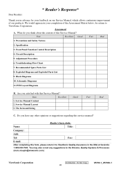
... 6. Exploded Diagram and Exploded Parts List 9. You may also e-mail any other opinions or suggestions regarding this service manual? Troubleshooting Flow Chart 7. Schematic Diagrams 11.PCB Layout Diagrams B. Are you in the USA at facsimile 1-909-839-7943. The form...Service Manual, which allows continuous improvement of this form, please return it to ViewSonic Quality Assurance in advance for return to the Director, Quality Systems & Processes (marc.maupin@viewsonic.com) ViewSonic Corporation Confidential - Block Diagrams 10. Do you think about the content of ...
... 6. Exploded Diagram and Exploded Parts List 9. You may also e-mail any other opinions or suggestions regarding this service manual? Troubleshooting Flow Chart 7. Schematic Diagrams 11.PCB Layout Diagrams B. Are you in the USA at facsimile 1-909-839-7943. The form...Service Manual, which allows continuous improvement of this form, please return it to ViewSonic Quality Assurance in advance for return to the Director, Quality Systems & Processes (marc.maupin@viewsonic.com) ViewSonic Corporation Confidential - Block Diagrams 10. Do you think about the content of ...