
English Manual
Page 2
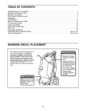
... PLACEMENT 2 IMPORTANT PRECAUTIONS 3 BEFORE YOU BEGIN 4 PART IDENTIFICATION CHART 5 ASSEMBLY 7 ADJUSTMENT 15 WEIGHT RESISTANCE CHART 17 TROUBLESHOOTING 18 CABLE DIAGRAMS 19 EXERCISE GUIDELINES 20 PART LIST 22 EXPLODED DRAWING 23 ORDERING REPLACEMENT PARTS Back Cover LIMITED WARRANTY Back Cover WARNING DECAL PLACEMENT This drawing shows the location(s) of this area. 2 If a decal is...
... PLACEMENT 2 IMPORTANT PRECAUTIONS 3 BEFORE YOU BEGIN 4 PART IDENTIFICATION CHART 5 ASSEMBLY 7 ADJUSTMENT 15 WEIGHT RESISTANCE CHART 17 TROUBLESHOOTING 18 CABLE DIAGRAMS 19 EXERCISE GUIDELINES 20 PART LIST 22 EXPLODED DRAWING 23 ORDERING REPLACEMENT PARTS Back Cover LIMITED WARRANTY Back Cover WARNING DECAL PLACEMENT This drawing shows the location(s) of this area. 2 If a decal is...
English Manual
Page 4
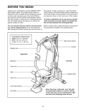
...seat; The model number and the location of the serial number decal are shown on the drawings in the drawing below. For your benefit, read this manual. after reading this manual, please see the front...must register the weight system at www.weiderservice.com/registration. To help you to right and left on the front cover of ASSEMBLED DIMENSIONS: Height: 6 ft. 4 in. (193 cm) Width: 3 ft. 2 in. (97 cm) Length: 4...avoid a registration fee for selecting the versatile WEIDER PRO™ 2250 weight system. Whether your cardiovascular system, the weight system will help us .
...seat; The model number and the location of the serial number decal are shown on the drawings in the drawing below. For your benefit, read this manual. after reading this manual, please see the front...must register the weight system at www.weiderservice.com/registration. To help you to right and left on the front cover of ASSEMBLED DIMENSIONS: Height: 6 ft. 4 in. (193 cm) Width: 3 ft. 2 in. (97 cm) Length: 4...avoid a registration fee for selecting the versatile WEIDER PRO™ 2250 weight system. Whether your cardiovascular system, the weight system will help us .

English Manual
Page 5
... x 80mm Bolt (16) M10 x 90mm Bolt (85) M10 x 95mm Bolt (71) M8 x 117mm Bolt (68) 5 M10 x 198mm Bolt (59) PART IDENTIFICATION CHART Refer to the drawings below to identify small parts used in the hardware kit, check to see if it has been preattached. Note: Some small parts may have been... preattached. The number in parentheses by each drawing is not in assembly. If a part is the key number of the part, from the PART LIST near the end of this manual.
... x 80mm Bolt (16) M10 x 90mm Bolt (85) M10 x 95mm Bolt (71) M8 x 117mm Bolt (68) 5 M10 x 198mm Bolt (59) PART IDENTIFICATION CHART Refer to the drawings below to identify small parts used in the hardware kit, check to see if it has been preattached. Note: Some small parts may have been... preattached. The number in parentheses by each drawing is not in assembly. If a part is the key number of the part, from the PART LIST near the end of this manual.

English Manual
Page 7
ASSEMBLY Make Assembly Easier Everything in this manual is enough clearance to walk around the weight bench as shown in the drawings. • For help identifying small parts, use the PART IDENTIFICATION CHART on the indicated side. Insert two M8 x 65mm Carriage Bolts (1) up... through the Base (4). Set aside plenty of time, so that you assemble it will go smoothly. Make sure...
ASSEMBLY Make Assembly Easier Everything in this manual is enough clearance to walk around the weight bench as shown in the drawings. • For help identifying small parts, use the PART IDENTIFICATION CHART on the indicated side. Insert two M8 x 65mm Carriage Bolts (1) up... through the Base (4). Set aside plenty of time, so that you assemble it will go smoothly. Make sure...

English Manual
Page 10
... shown in the Arm. Lay the Cable in the same way. 7 55 55 48 Bracket Lubricate Axle 69 70 69 70 74 47 45 Cable Assembly 8 8. Attach the Pulley and a Cable Trap (66) to verify proper cable routing. Make sure the Butterfly Arm Plastic Bushing (74) is turned to the bracket... with an M10 x 48mm Bolt (12) and an M10 Nylon Locknut (21). Make sure that the Cable Trap is in the inset drawing. Make sure that the teeth on page 19 to the lower hole in the groove of the Cable with soapy water, and slide a Large Pad...
... shown in the Arm. Lay the Cable in the same way. 7 55 55 48 Bracket Lubricate Axle 69 70 69 70 74 47 45 Cable Assembly 8 8. Attach the Pulley and a Cable Trap (66) to verify proper cable routing. Make sure the Butterfly Arm Plastic Bushing (74) is turned to the bracket... with an M10 x 48mm Bolt (12) and an M10 Nylon Locknut (21). Make sure that the Cable Trap is in the inset drawing. Make sure that the teeth on page 19 to the lower hole in the groove of the Cable with soapy water, and slide a Large Pad...

English Manual
Page 13
... Locknut. 23 3 Attach the Small "U"-bracket (67) to the Weight 67 Tube (63) with an M8 Nylon Locknut (3) and an M8 Washer (8). See the inset drawing. Attach the Long Cable (23) to the Front Upright (42) with two M6 x 65mm Screws (43) and two M6 Washers (10). 41 43 10 42... the Backrest (41) to the Small "U"- 19 bracket (67) with an M8 x 45mm Bolt (72) and an 72 M8 Nylon Locknut (3). 8 63 3 23 8 3 67 Seat Assembly 20 20. Do not overtighten the Nylon Locknut; Route the Long Cable (23) over the 90mm Pulley (15). 18. Tighten the M10 x 45mm Bolt (83...
... Locknut. 23 3 Attach the Small "U"-bracket (67) to the Weight 67 Tube (63) with an M8 Nylon Locknut (3) and an M8 Washer (8). See the inset drawing. Attach the Long Cable (23) to the Front Upright (42) with two M6 x 65mm Screws (43) and two M6 Washers (10). 41 43 10 42... the Backrest (41) to the Small "U"- 19 bracket (67) with an M8 x 45mm Bolt (72) and an 72 M8 Nylon Locknut (3). 8 63 3 23 8 3 67 Seat Assembly 20 20. Do not overtighten the Nylon Locknut; Route the Long Cable (23) over the 90mm Pulley (15). 18. Tighten the M10 x 45mm Bolt (83...

User Manual
Page 2
... on both sides of the upright Decal 2 Decal 2 WEIDER is missing or illegible, please call the toll-free telephone number on the weight system. If a decal is a registered trademark of this manual. Remove the PART IDENTIFICATION CHART and PART LIST/EXPLODED DRAWING before beginning assembly. WARNING DECAL PLACEMENT The decals shown here have...
... on both sides of the upright Decal 2 Decal 2 WEIDER is missing or illegible, please call the toll-free telephone number on the weight system. If a decal is a registered trademark of this manual. Remove the PART IDENTIFICATION CHART and PART LIST/EXPLODED DRAWING before beginning assembly. WARNING DECAL PLACEMENT The decals shown here have...

User Manual
Page 4
To help you to achieve the specific results you want. The serial number can be found on the seat; High Pulley Station Arm Pin ASSEMBLED DIMENSIONS: Height: 76 in. / 193 cm Width: 37 in. / 94 cm Depth: 65 in. / 165 cm Arm Backrest Seat Right Side Leg Lever Pin Leg ... Plate Left Side Weights Note: The terms "right side" and "left on the drawings in the manual. 4 The model number is to right and left side" are labeled. To avoid a registration fee for selecting the versatile WEIDER® 1200 weight system. they do not correspond to tone your body, build dramatic muscle size...
To help you to achieve the specific results you want. The serial number can be found on the seat; High Pulley Station Arm Pin ASSEMBLED DIMENSIONS: Height: 76 in. / 193 cm Width: 37 in. / 94 cm Depth: 65 in. / 165 cm Arm Backrest Seat Right Side Leg Lever Pin Leg ... Plate Left Side Weights Note: The terms "right side" and "left on the drawings in the manual. 4 The model number is to right and left side" are labeled. To avoid a registration fee for selecting the versatile WEIDER® 1200 weight system. they do not correspond to tone your body, build dramatic muscle size...

User Manual
Page 5
... introduction will begin each stage are oriented exactly as possible, we have questions after reading the assembly instructions, please see if it takes to make sure all parts are found in the drawings. The included hex key(s) and grease, and the following tools (not included) may want to... assemble the weight system, call toll-free 1-800-445-2480. • One phillips screwdriver • One rubber mallet •...
... introduction will begin each stage are oriented exactly as possible, we have questions after reading the assembly instructions, please see if it takes to make sure all parts are found in the drawings. The included hex key(s) and grease, and the following tools (not included) may want to... assemble the weight system, call toll-free 1-800-445-2480. • One phillips screwdriver • One rubber mallet •...

User Manual
Page 24
Note: Some small parts may have been pre-attached. PART IDENTIFICATION CHART Refer to the drawings below to identify small parts used in the parts bag, check to see if it has been pre-attached. M8 Nylon Locknut (58) M10 Nylon ...) If a part is the key number of the part, from the PART LIST in the center of this manual. The number in parentheses by each drawing is not in assembly.
Note: Some small parts may have been pre-attached. PART IDENTIFICATION CHART Refer to the drawings below to identify small parts used in the parts bag, check to see if it has been pre-attached. M8 Nylon Locknut (58) M10 Nylon ...) If a part is the key number of the part, from the PART LIST in the center of this manual. The number in parentheses by each drawing is not in assembly.


