

English Manual
Page 1
I WEIDER HEALTH AND FITNESS 21100 Erwin Street, Woodland Hills, California, U.SA 91367 Z2 - 87 • • 0 I -i WB-330 CLASSIC Assembly Instructions I ? -
I WEIDER HEALTH AND FITNESS 21100 Erwin Street, Woodland Hills, California, U.SA 91367 Z2 - 87 • • 0 I -i WB-330 CLASSIC Assembly Instructions I ? -
English Manual
Page 2
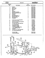
Parts List Part Name 1 Upright 2 Base Frame 3 Main Frame 4 Backrest 5 Seat 6 Leg Curl 7 Adjustable Uprights 8 Backrest Adjustment Bar 9 Foam Pad 10 Pad Bars 11 Seat Adjustment "T" 12 Backrest Angle Iron 13 Seat Angle Iron 14 U-Bracket A 5/16"-20 x 2" Hex Head Bolt B 5/16"-20 Lock Nut C 3/8"-16 x 2 1/2" Hex Head Bolt D 3/8"-16 Lock Nut E 1/4"-20 x 3/4" Hex Head Bolt F 1/4"-20 Lock Nut G Locking Pin (Small) H Locking Pin (Large) J 1 1/2" Square Plastic Cap K 1" Round Plastic...
Parts List Part Name 1 Upright 2 Base Frame 3 Main Frame 4 Backrest 5 Seat 6 Leg Curl 7 Adjustable Uprights 8 Backrest Adjustment Bar 9 Foam Pad 10 Pad Bars 11 Seat Adjustment "T" 12 Backrest Angle Iron 13 Seat Angle Iron 14 U-Bracket A 5/16"-20 x 2" Hex Head Bolt B 5/16"-20 Lock Nut C 3/8"-16 x 2 1/2" Hex Head Bolt D 3/8"-16 Lock Nut E 1/4"-20 x 3/4" Hex Head Bolt F 1/4"-20 Lock Nut G Locking Pin (Small) H Locking Pin (Large) J 1 1/2" Square Plastic Cap K 1" Round Plastic...
English Manual
Page 3
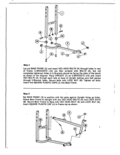
... Frame top as shown. 0 • 3 _r- Step 2 Set MAIN FRAME (3) in rear of Upright making sure bolt passes through holes in position with LOCK NUT (B). Attach Main Frame to Base with two HEX HEAD BOLTS (A) and LOCK NUTS (B). Tighten all bolts. 0 O 0 al 0 al 2 O O O 00 O Step 1 Lay out BASE FRAME (2) and insert HEX HEAD BOLTS (A) through U-Bracket holes. Secure Main Frame to...
... Frame top as shown. 0 • 3 _r- Step 2 Set MAIN FRAME (3) in rear of Upright making sure bolt passes through holes in position with LOCK NUT (B). Attach Main Frame to Base with two HEX HEAD BOLTS (A) and LOCK NUTS (B). Tighten all bolts. 0 O 0 al 0 al 2 O O O 00 O Step 1 Lay out BASE FRAME (2) and insert HEX HEAD BOLTS (A) through U-Bracket holes. Secure Main Frame to...
English Manual
Page 4
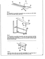
5 13 Step 3 Turn BACKREST (4) and SEAT (5) assembly over one side of Seat Angle Iron with seat holes and replace HEX HEAD BOLTS (N). 3 Align holes of pivot rod. Use EYELET PIN (M) to free SEAT ANGLE IRON (13). 4 0 5 M Step 4 Turn BACKREST (4) and SEAT (5) assembly right side up and lower onto Main Frame. Align SEAT ADJUSTMENT "T" (11) over slot in Main Frame and slide secured Seat Angle Iron over and remove two HEX HEAD BOLTS (N) to adjust Backrest and Seat height. 13 N Step 5 Slide SEAT ANGLE IRON (13) onto SEAT ADJUSTMENT "T" rod.
5 13 Step 3 Turn BACKREST (4) and SEAT (5) assembly over one side of Seat Angle Iron with seat holes and replace HEX HEAD BOLTS (N). 3 Align holes of pivot rod. Use EYELET PIN (M) to free SEAT ANGLE IRON (13). 4 0 5 M Step 4 Turn BACKREST (4) and SEAT (5) assembly right side up and lower onto Main Frame. Align SEAT ADJUSTMENT "T" (11) over slot in Main Frame and slide secured Seat Angle Iron over and remove two HEX HEAD BOLTS (N) to adjust Backrest and Seat height. 13 N Step 5 Slide SEAT ANGLE IRON (13) onto SEAT ADJUSTMENT "T" rod.
English Manual
Page 5
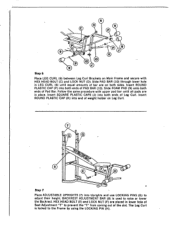
... equal amounts of bar are on Leg Curl. 7 G G O • 8 43 F H O 3 • Step 7 Place ADJUSTABLE UPRIGHTS (7) into Uprights and use LOCKING PINS (G) to prevent the "T" from coming out of the slot. Slide PAD BAR (10) through lower hole in LEG CURL (6) until all pads are in lower hole of Seat Adjustment "T" to adjust their height. Insert ROUND PLASTIC CAP (K) into end of weight holder on both ends...
... equal amounts of bar are on Leg Curl. 7 G G O • 8 43 F H O 3 • Step 7 Place ADJUSTABLE UPRIGHTS (7) into Uprights and use LOCKING PINS (G) to prevent the "T" from coming out of the slot. Slide PAD BAR (10) through lower hole in LEG CURL (6) until all pads are in lower hole of Seat Adjustment "T" to adjust their height. Insert ROUND PLASTIC CAP (K) into end of weight holder on both ends...
English Manual
Page 6
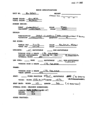
... BENCH SPECIFICATIONS UNIT NO. NON-ADJUSTABLE CLex...y...... ) I I YZ. *MIGHT ADJUSTMENTS VAN 'b • .Sc) *OVERALL WIDTH Zc:), c'e x-c-wptis LEG CURL: NONE *TUBING SIZE & SHAPE ADJUSTABLE 1.-- cZec:), QUANTITY -Z. %.401/00 4 ,e 4.,cr..4‹. WEIGHT • L •.••4 r4 SCREEN DESIGN: *SEAT Gy..1 .•417-.0%...) *BACKREST tvi COLOR COLOR 1 Z . --P DECALS : *DESCRIPTION *LOCATION L, P17-1.4.'.-X-V%. PAD SIZES: *ANKLE PAD *KNEE PAD 7, •rc 5 COLOR COLOR UPRIGHTS: V"- FRAME...
... BENCH SPECIFICATIONS UNIT NO. NON-ADJUSTABLE CLex...y...... ) I I YZ. *MIGHT ADJUSTMENTS VAN 'b • .Sc) *OVERALL WIDTH Zc:), c'e x-c-wptis LEG CURL: NONE *TUBING SIZE & SHAPE ADJUSTABLE 1.-- cZec:), QUANTITY -Z. %.401/00 4 ,e 4.,cr..4‹. WEIGHT • L •.••4 r4 SCREEN DESIGN: *SEAT Gy..1 .•417-.0%...) *BACKREST tvi COLOR COLOR 1 Z . --P DECALS : *DESCRIPTION *LOCATION L, P17-1.4.'.-X-V%. PAD SIZES: *ANKLE PAD *KNEE PAD 7, •rc 5 COLOR COLOR UPRIGHTS: V"- FRAME...


