

Uk Manual
Page 1
... Revie Road, Beeston Leeds, LS11 8JG, UK CAUTION Read all precautions and instructions in the space above for future reference. USER'S MANUAL Visit our website at the numbers or addresses listed below: Call: 08457 089 009 Outside UK: 0 (44) 113 3877133 Fax: 0 (44) 113 3877125 E-mail: [email protected] Write: ICON Health & Fitness, Ltd. WEFMBE1477.0 Serial No. Model No. Serial Number Decal QUESTIONS?
... Revie Road, Beeston Leeds, LS11 8JG, UK CAUTION Read all precautions and instructions in the space above for future reference. USER'S MANUAL Visit our website at the numbers or addresses listed below: Call: 08457 089 009 Outside UK: 0 (44) 113 3877133 Fax: 0 (44) 113 3877125 E-mail: [email protected] Write: ICON Health & Fitness, Ltd. WEFMBE1477.0 Serial No. Model No. Serial Number Decal QUESTIONS?

Uk Manual
Page 2
WIEDER is missing or illegible, call the telephone number on the front cover of ICON IP, Inc. 2 TABLE OF CONTENTS WARNING DECAL PLACEMENT 2 IMPORTANT PRECAUTIONS 3 BEFORE YOU BEGIN 4 PART IDENTIFICATION CHART 5 ASSEMBLY 6 ADJUSTMENT 9 PART LIST 10 EXPLODED DRAWING 11 ORDERING REPLACEMENT PARTS Back Cover WARNING DECAL PLACEMENT The decals shown here have been applied in the location shown. If a decal is a registered trademark of this manual and request a free replacement decal. Note: The decals may not be shown at actual size. Apply the decal in the locations shown.
WIEDER is missing or illegible, call the telephone number on the front cover of ICON IP, Inc. 2 TABLE OF CONTENTS WARNING DECAL PLACEMENT 2 IMPORTANT PRECAUTIONS 3 BEFORE YOU BEGIN 4 PART IDENTIFICATION CHART 5 ASSEMBLY 6 ADJUSTMENT 9 PART LIST 10 EXPLODED DRAWING 11 ORDERING REPLACEMENT PARTS Back Cover WARNING DECAL PLACEMENT The decals shown here have been applied in the location shown. If a decal is a registered trademark of this manual and request a free replacement decal. Note: The decals may not be shown at actual size. Apply the decal in the locations shown.

Uk Manual
Page 3
... pets away from moving parts. 8. The weight training system should not be used by or through the use only. It is the responsibility of the owner to ensure that all users of the weight training system are adequately informed of serious injury, read all instructions in any commercial, rental, or institutional setting. 3 Wear appropriate clothes while exercising. Cover the floor beneath the weight training system to prevent...
... pets away from moving parts. 8. The weight training system should not be used by or through the use only. It is the responsibility of the owner to ensure that all users of the weight training system are adequately informed of serious injury, read all instructions in any commercial, rental, or institutional setting. 3 Wear appropriate clothes while exercising. Cover the floor beneath the weight training system to prevent...

Uk Manual
Page 4
... the specific results you want. Rail Seat Stabilizer Handgrip Support Leg Handle Adjustment Foot Adjustment Leg Adjustment Bracket 4 If you , note the product model number and serial number before using the weight training system. Before reading further, please review the drawing below and familiarize yourself with the parts that are shown on the front cover of this manual. To help you for selecting the WEIDER® BODY WORKS PRO 2.0 weight training system. The model number and the location...
... the specific results you want. Rail Seat Stabilizer Handgrip Support Leg Handle Adjustment Foot Adjustment Leg Adjustment Bracket 4 If you , note the product model number and serial number before using the weight training system. Before reading further, please review the drawing below and familiarize yourself with the parts that are shown on the front cover of this manual. To help you for selecting the WEIDER® BODY WORKS PRO 2.0 weight training system. The model number and the location...

Uk Manual
Page 5
... Locknut (12) M10 x 25mm Screw (36) 5 Note: Some parts may have been preassembled for shipping purposes. M6 x 138mm Bolt (31) PART IDENTIFICATION CHART This chart is provided to help you cannot find a part in the parts bags, check to the key number of the part, from the PART LIST near the end of this manual. If you identify the small parts used in parenthesis below each...
... Locknut (12) M10 x 25mm Screw (36) 5 Note: Some parts may have been preassembled for shipping purposes. M6 x 138mm Bolt (31) PART IDENTIFICATION CHART This chart is provided to help you cannot find a part in the parts bags, check to the key number of the part, from the PART LIST near the end of this manual. If you identify the small parts used in parenthesis below each...

Uk Manual
Page 6
.... Then, attach the Stabilizer to the Adjustment Leg (8) with two M10 x 1 25mm Screws (36) and two M10 Washers (35). 3 35 35 36 4 2. Do not dispose of the packing materials until assembly is completed. • Tighten all parts in the drawings. • Assembly requires two persons. • For help identifying small parts, use the PART IDENTIFICATION CHART on page 5. ASSEMBLY Make Assembly Easier This manual is...
.... Then, attach the Stabilizer to the Adjustment Leg (8) with two M10 x 1 25mm Screws (36) and two M10 Washers (35). 3 35 35 36 4 2. Do not dispose of the packing materials until assembly is completed. • Tighten all parts in the drawings. • Assembly requires two persons. • For help identifying small parts, use the PART IDENTIFICATION CHART on page 5. ASSEMBLY Make Assembly Easier This manual is...
Uk Manual
Page 7
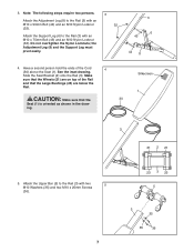
...) are on top of the Cord 4 (30) above the Seat (1). 3. Note: The following steps require two persons. 3 Attach the Adjustment Leg (8) to the Rail (3) with two 5 M10 Washers (35) and two M10 x 25mm Screws (36). 7 23 3 23 5 3 35 35 36 ing. Slide the Seat Bracket (2) onto the Rail (3). Silkscreen 1 3 21 2 21 5. Attach the Upper Bar (5) to the Rail (3) with an...
...) are on top of the Cord 4 (30) above the Seat (1). 3. Note: The following steps require two persons. 3 Attach the Adjustment Leg (8) to the Rail (3) with two 5 M10 Washers (35) and two M10 x 25mm Screws (36). 7 23 3 23 5 3 35 35 36 ing. Slide the Seat Bracket (2) onto the Rail (3). Silkscreen 1 3 21 2 21 5. Attach the Upper Bar (5) to the Rail (3) with an...

Uk Manual
Page 8
Repeat this step with the M10 x 30mm Bolt (45) and the M10 Nylon Locknut (32). Reattach the Large Pulley inside the Pulley Housing (16) with the other Pulley Housing (16). the Pulley must turn easily. The use the weight training system. Attach a Handle (28) to each end of the remaining parts will be explained in ADJUSTMENT on page 9. 8 Wrap one of the Cord (30) around...
Repeat this step with the M10 x 30mm Bolt (45) and the M10 Nylon Locknut (32). Reattach the Large Pulley inside the Pulley Housing (16) with the other Pulley Housing (16). the Pulley must turn easily. The use the weight training system. Attach a Handle (28) to each end of the remaining parts will be explained in ADJUSTMENT on page 9. 8 Wrap one of the Cord (30) around...

Uk Manual
Page 9
... own body weight as resistance. The weight training system can be adjusted and folded for several exercises. Raise or lower the Rail to the desired incline and insert the knob into an adjustment hole in the Adjustment Leg. The steps below explain how the weight training system can be attached to the weight training system. Refer to the accompanying exercise guide to see the correct form for storage. ADJUSTMENT The weight training system is designed to use your workout.
... own body weight as resistance. The weight training system can be adjusted and folded for several exercises. Raise or lower the Rail to the desired incline and insert the knob into an adjustment hole in the Adjustment Leg. The steps below explain how the weight training system can be attached to the weight training system. Refer to the accompanying exercise guide to see the correct form for storage. ADJUSTMENT The weight training system is designed to use your workout.

Uk Manual
Page 10
... 42 2 M10 x 55mm Bolt 43 2 M10 x 75mm Bolt 44 1 M10 x 90mm Bolt 45 2 M10 x 30mm Bolt 46 1 M4 x 20mm Self-tapping Screw 47 1 M6 Nylon Locknut 48 2 M6 x 25mm Screw 49 2 Plastic Knob * - Qty. Qty. See the back cover for information on ordering replacement parts. *These parts are subject to change without notice. PART LIST-Model No. Workout Chart Note: Specifications are not illustrated. 10 User's Manual * - Description Key No. WEFMBE1477.0 R0707A...
... 42 2 M10 x 55mm Bolt 43 2 M10 x 75mm Bolt 44 1 M10 x 90mm Bolt 45 2 M10 x 30mm Bolt 46 1 M4 x 20mm Self-tapping Screw 47 1 M6 Nylon Locknut 48 2 M6 x 25mm Screw 49 2 Plastic Knob * - Qty. Qty. See the back cover for information on ordering replacement parts. *These parts are subject to change without notice. PART LIST-Model No. Workout Chart Note: Specifications are not illustrated. 10 User's Manual * - Description Key No. WEFMBE1477.0 R0707A...

Uk Manual
Page 11
WEFMBE1477.0 R0707A 30 25 26 29 24 27 28 26 25 13 33 18 45 16 32 15 34 5 33 34 18 13 45 16 22 2341 12 40 39 21 1 39 38 37 14 37 38 39 21 39 40 41 23 22 2 22 2341 12 39 2139 38 40 37 40 37 38 39 21 39 14 39 41 2322 12 17 39 3 12 12 32 32 32 8 44 11 35 36 20 46 43 6 42 43 35 10 32 15 9 10 31 11 48 19 49 19 47 35 36 4 7 35 35 32 11 11 11 EXPLODED DRAWING-Model No.
WEFMBE1477.0 R0707A 30 25 26 29 24 27 28 26 25 13 33 18 45 16 32 15 34 5 33 34 18 13 45 16 22 2341 12 40 39 21 1 39 38 37 14 37 38 39 21 39 40 41 23 22 2 22 2341 12 39 2139 38 40 37 40 37 38 39 21 39 14 39 41 2322 12 17 39 3 12 12 32 32 32 8 44 11 35 36 20 46 43 6 42 43 35 10 32 15 9 10 31 11 48 19 49 19 47 35 36 4 7 35 35 32 11 11 11 EXPLODED DRAWING-Model No.

Uk Manual
Page 12
To help us assist you, be prepared to provide the following information when contacting us: • the model number and serial number of the product (see the front cover of the manual) • the name of the product (see the front cover of the manual) • the key number and description of the part(s) (see the front cover of this manual. ORDERING REPLACEMENT PARTS To order replacement parts, please see the PART LIST and the EXPLODED DRAWING near the end of this manual) Part No. 256999 R0707A Printed in China © 2007 ICON IP, Inc.
To help us assist you, be prepared to provide the following information when contacting us: • the model number and serial number of the product (see the front cover of the manual) • the name of the product (see the front cover of the manual) • the key number and description of the part(s) (see the front cover of this manual. ORDERING REPLACEMENT PARTS To order replacement parts, please see the PART LIST and the EXPLODED DRAWING near the end of this manual) Part No. 256999 R0707A Printed in China © 2007 ICON IP, Inc.


