

English Manual
Page 4
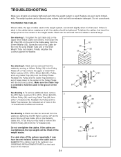
... system. 1. If the cables bind as described in any worn parts immediately. 6. Cover the floor beneath the weight system to tip. 12. Never release the butterfly arms, leg lever, lat bar, leg press, or accessories while weights are adequately informed of all instructions before using . Make sure that does not use...
... system. 1. If the cables bind as described in any worn parts immediately. 6. Cover the floor beneath the weight system to tip. 12. Never release the butterfly arms, leg lever, lat bar, leg press, or accessories while weights are adequately informed of all instructions before using . Make sure that does not use...

English Manual
Page 5
The model number is to achieve the specific results you for selecting the versatile WEIDER® CLUB C4800 weight system. and familiarize yourself with the parts that are labeled. Shroud Backrest Lat Bar High Pulley Station AB Pulley Station Butterfly/Press Arm Weight Stack Seat Leg Press Curl Pad Leg Lever Low Pulley Station Foot...
The model number is to achieve the specific results you for selecting the versatile WEIDER® CLUB C4800 weight system. and familiarize yourself with the parts that are labeled. Shroud Backrest Lat Bar High Pulley Station AB Pulley Station Butterfly/Press Arm Weight Stack Seat Leg Press Curl Pad Leg Lever Low Pulley Station Foot...

English Manual
Page 7
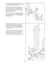
... a 50mm Square Inner Cap (45) into the Base (1). Insert three M10 x 92mm Carriage Bolts (85) and an M10 x 121mm Carriage Bolt (49) up into the Butterfly Upright (2). Frame Assembly 1 1. Slide the Leg Press Base (3) onto the indicated M10 x 92mm Carriage Bolt (85) and the M10 x 121mm Carriage Bolt (49). Before beginning... M10 x 92mm Carriage Bolt. Do not tighten the Locknuts yet. 46 101 49 85 2 46 46 46 1 85 3 46 46 2 45 101 85 7 Slide the Butterfly Upright (2) on page 6. Press four 50mm x 75mm Inner Caps (46) into the Base (1) and the Leg Press Base (3).
... a 50mm Square Inner Cap (45) into the Base (1). Insert three M10 x 92mm Carriage Bolts (85) and an M10 x 121mm Carriage Bolt (49) up into the Butterfly Upright (2). Frame Assembly 1 1. Slide the Leg Press Base (3) onto the indicated M10 x 92mm Carriage Bolt (85) and the M10 x 121mm Carriage Bolt (49). Before beginning... M10 x 92mm Carriage Bolt. Do not tighten the Locknuts yet. 46 101 49 85 2 46 46 46 1 85 3 46 46 2 45 101 85 7 Slide the Butterfly Upright (2) on page 6. Press four 50mm x 75mm Inner Caps (46) into the Base (1) and the Leg Press Base (3).
English Manual
Page 8
... Bolts (80), four M10 Washers (99), four 12.5mm Spacers (69), and two M10 Nylon Locknuts (101). Attach the Weight Guides with Rings to the Butterfly Upright (2) with two M10 x 65mm Carriage Bolts (88) and two M10 Nylon Locknuts (101).
... Bolts (80), four M10 Washers (99), four 12.5mm Spacers (69), and two M10 Nylon Locknuts (101). Attach the Weight Guides with Rings to the Butterfly Upright (2) with two M10 x 65mm Carriage Bolts (88) and two M10 Nylon Locknuts (101).
English Manual
Page 10
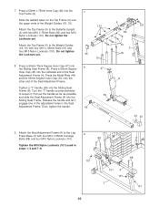
... Bolts (82) and two M10 Nylon Locknuts (101). Press a 50mm x 75mm Inner Cap (46) into the Sliding Seat Frame. Turn the "T"-handle counterclockwise to the Butterfly Upright (2) with four M10 x 45mm Bolts (51) and four M10 Nylon Locknuts (101). Attach the Top Frame (9) to loosen it engage one of the Weight...
... Bolts (82) and two M10 Nylon Locknuts (101). Press a 50mm x 75mm Inner Cap (46) into the Sliding Seat Frame. Turn the "T"-handle counterclockwise to the Butterfly Upright (2) with four M10 x 45mm Bolts (51) and four M10 Nylon Locknuts (101). Attach the Top Frame (9) to loosen it engage one of the Weight...
English Manual
Page 11
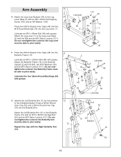
... 10 53 Lubricate 12. Press a 50mm Round Inner Cap (52) and a 25mm Round Inner Cap (76) into the 11 Butterfly Frame (10). Lubricate an M10 x 85mm Bolt (96) with the Right Butterfly Arm (12). 12 12 93 10 101 Bracket 11 76 52 11 Press two 50mm Square Inner Caps (45) into... the Butterfly Arm. Do not overtighten the Locknut; the Butterfly Frame must be able to the Butterfly Frame (10) with the Bolt, two M10 Washers (99), and an M10 Nylon Locknut (101). Attach the Left...
... 10 53 Lubricate 12. Press a 50mm Round Inner Cap (52) and a 25mm Round Inner Cap (76) into the 11 Butterfly Frame (10). Lubricate an M10 x 85mm Bolt (96) with the Right Butterfly Arm (12). 12 12 93 10 101 Bracket 11 76 52 11 Press two 50mm Square Inner Caps (45) into... the Butterfly Arm. Do not overtighten the Locknut; the Butterfly Frame must be able to the Butterfly Frame (10) with the Bolt, two M10 Washers (99), and an M10 Nylon Locknut (101). Attach the Left...
English Manual
Page 13
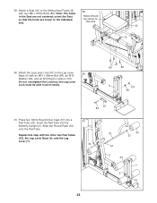
Route the Cable up through the Butterfly Upright (2), so that the ball is in step 15. The two holes in the welded tube must be closer to hold the Cable in the ...
Route the Cable up through the Butterfly Upright (2), so that the ball is in step 15. The two holes in the welded tube must be closer to hold the Cable in the ...
English Manual
Page 16
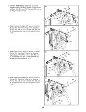
... M10 x 65mm Bolt (80), two M10 Washers (99), and an M10 Nylon Locknut (101). 31. Wrap the Butterfly Cable (67) around a 100mm 32 Pulley (38). Identify the Butterfly Cable (67). Attach the Pulley to the Butterfly Upright (2) with an M10 x 213mm Bolt (92), two M10 Washers (99), and an M10 Nylon Locknut (101... 67 69 2 101 33 38 67 99 101 80 99 69 92 99 10 67 38 99 101 16 Attach the 30 Cable inside the Butterfly Upright (2) with an M10 x 213mm Bolt (92), two M10 Washers (99), and an M10 Nylon Locknut (101). 80 99 101 67 99 2 92 10 99...
... M10 x 65mm Bolt (80), two M10 Washers (99), and an M10 Nylon Locknut (101). 31. Wrap the Butterfly Cable (67) around a 100mm 32 Pulley (38). Identify the Butterfly Cable (67). Attach the Pulley to the Butterfly Upright (2) with an M10 x 213mm Bolt (92), two M10 Washers (99), and an M10 Nylon Locknut (101... 67 69 2 101 33 38 67 99 101 80 99 69 92 99 10 67 38 99 101 16 Attach the 30 Cable inside the Butterfly Upright (2) with an M10 x 213mm Bolt (92), two M10 Washers (99), and an M10 Nylon Locknut (101). 80 99 101 67 99 2 92 10 99...
English Manual
Page 17
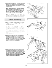
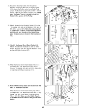
34. Attach the end of the weight system. ly tighten the Locknut; Note: The following steps are shown from the 38 back of the Butterfly Cable (67) to the 35 "U"-bracket (40) with an M8 Washer (100) and an 67 M8 Nylon Locknut (87). ing. 100 87 36. Wrap the ... of the Pulley. 17 1 100 64 90 42 51 38 101 64 38 1 68 64 51 Make sure the Cable Trap is oriented to the Butterfly Upright with an M8 x 67mm Shoulder Bolt (90), two M8 Washers (100), and an M8 Nylon Locknut (87). 87 100 67 87 37. Route the...
34. Attach the end of the weight system. ly tighten the Locknut; Note: The following steps are shown from the 38 back of the Butterfly Cable (67) to the 35 "U"-bracket (40) with an M8 Washer (100) and an 67 M8 Nylon Locknut (87). ing. 100 87 36. Wrap the ... of the Pulley. 17 1 100 64 90 42 51 38 101 64 38 1 68 64 51 Make sure the Cable Trap is oriented to the Butterfly Upright with an M8 x 67mm Shoulder Bolt (90), two M8 Washers (100), and an M8 Nylon Locknut (87). 87 100 67 87 37. Route the...
English Manual
Page 20
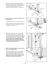
... Leg Lever Base (5) with an M10 x 50mm Bolt (81) and an M10 Nylon Locknut (101). Attach the Pulley and a Long Cable Trap (68) to the Butterfly Upright (2) with an M10 x 45mm Bolt (51) and an M10 Nylon Locknut (101). 50 Brackets 51 38 1 101 66 51. Wrap the Ab Cable (66...) under a 100mm Pulley (38). Attach the Pulley and a Long Cable Trap (68) to the second set of holes from the 52 back of the Butterfly Upright (2). 52. Make sure the Cable is oriented to hold the Cable in the indicated brackets. Wrap the Ab Cable (66) over the Pulley toward...
... Leg Lever Base (5) with an M10 x 50mm Bolt (81) and an M10 Nylon Locknut (101). Attach the Pulley and a Long Cable Trap (68) to the Butterfly Upright (2) with an M10 x 45mm Bolt (51) and an M10 Nylon Locknut (101). 50 Brackets 51 38 1 101 66 51. Wrap the Ab Cable (66...) under a 100mm Pulley (38). Attach the Pulley and a Long Cable Trap (68) to the second set of holes from the 52 back of the Butterfly Upright (2). 52. Make sure the Cable is oriented to hold the Cable in the indicated brackets. Wrap the Ab Cable (66) over the Pulley toward...
English Manual
Page 21
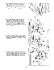
... 81 101 2 54. Route the Ab Cable (66) over a 100mm Pulley 54 (38). Wrap the Ab Cable (66) over a 100mm Pulley (38) and through the Butterfly Upright (2). Make sure the Cable Trap is oriented to hold the Cable in the indicated "U"- Wrap the Ab Cable (66) under a 100mm Pulley 53 (38...). 53. Attach the Pulley and a Long Cable Trap (68) to the Butterfly Upright (2) with an M10 x 65mm Bolt (80), two M10 Washers (99), two 12.5mm Spacers (69), and an M10 Nylon Locknut (101). 38 99 101...
... 81 101 2 54. Route the Ab Cable (66) over a 100mm Pulley 54 (38). Wrap the Ab Cable (66) over a 100mm Pulley (38) and through the Butterfly Upright (2). Make sure the Cable Trap is oriented to hold the Cable in the indicated "U"- Wrap the Ab Cable (66) under a 100mm Pulley 53 (38...). 53. Attach the Pulley and a Long Cable Trap (68) to the Butterfly Upright (2) with an M10 x 65mm Bolt (80), two M10 Washers (99), two 12.5mm Spacers (69), and an M10 Nylon Locknut (101). 38 99 101...
English Manual
Page 23
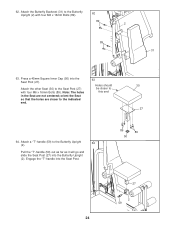
.... 59 Holes should be able to the Sliding Seat Frame (8) with four M6 x 16mm Bolts (89). Press two 19mm Round Inner Caps (57) into the Butterfly Upright (2). Attach a Seat (30) to pivot easily. 89 89 5 101 99 61 84 61.
.... 59 Holes should be able to the Sliding Seat Frame (8) with four M6 x 16mm Bolts (89). Press two 19mm Round Inner Caps (57) into the Butterfly Upright (2). Attach a Seat (30) to pivot easily. 89 89 5 101 99 61 84 61.
English Manual
Page 24
... Post (27). Note: The holes in the Seat are closer to the indicated end. 63 Holes should be closer to the Butterfly Upright 64 (2). Attach the other Seat (30) to the Butterfly Upright (2) with four M6 x 16mm Bolts (89). Press a 45mm Square Inner Cap (50) into the Seat Post. 89 89 50... 27 2 59 24 Attach the Butterfly Backrest (31) to the Seat Post (27) with four M6 x 16mm Bolts (89). 62 89 2 89 31 63. Pull the "T"-handle (59) out as far ...
... Post (27). Note: The holes in the Seat are closer to the indicated end. 63 Holes should be closer to the Butterfly Upright 64 (2). Attach the other Seat (30) to the Butterfly Upright (2) with four M6 x 16mm Bolts (89). Press a 45mm Square Inner Cap (50) into the Seat Post. 89 89 50... 27 2 59 24 Attach the Butterfly Backrest (31) to the Seat Post (27) with four M6 x 16mm Bolts (89). 62 89 2 89 31 63. Pull the "T"-handle (59) out as far ...
English Manual
Page 25
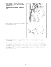
... is any slack in ADJUSTMENTS, beginning on page 31. 25 See the CABLE DIAGRAMS on pages 29 and 30 of this step with the other Butterfly Pin (78). 78 10 107 78 66. 65. Attach the Curl Pad (29) to remove the slack by tightening the cables. If one of the... over the pulleys. Before using the weight system, pull each cable a few times to the 65 Butterfly Frame (10) with 66 four M6 x 16mm Bolts (89). 89 89 29 28 67. Attach the tether on a Butterfly Pin (78) to be explained in the cables, you will be sure that all parts have...
... is any slack in ADJUSTMENTS, beginning on page 31. 25 See the CABLE DIAGRAMS on pages 29 and 30 of this step with the other Butterfly Pin (78). 78 10 107 78 66. 65. Attach the Curl Pad (29) to remove the slack by tightening the cables. If one of the... over the pulleys. Before using the weight system, pull each cable a few times to the 65 Butterfly Frame (10) with 66 four M6 x 16mm Bolts (89). 89 89 29 28 67. Attach the tether on a Butterfly Pin (78) to be explained in the cables, you will be sure that all parts have...
English Manual
Page 27
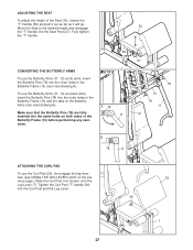
... to the desired height and reengage 30 the "T"-handle into the Curl Post and the Leg Lever. 29 94 7 27 A 78 Make sure that the Butterfly Pins (78) are fully inserted into the same holes on both sides of the Seat (30), loosen the "T"-handle (59) and pull it out as... drawing A). cises. 27 78 10 78 11 12 B 78 11 ATTACHING THE CURL PAD To use the Butterfly Arms (11, 12) as press arms, insert the Butterfly Pins (78) into the inner holes in the Butterfly Frame (10) and the tabs on the previous page.) Slide the Curl Post (not shown) onto the...
... to the desired height and reengage 30 the "T"-handle into the Curl Post and the Leg Lever. 29 94 7 27 A 78 Make sure that the Butterfly Pins (78) are fully inserted into the same holes on both sides of the Seat (30), loosen the "T"-handle (59) and pull it out as... drawing A). cises. 27 78 10 78 11 12 B 78 11 ATTACHING THE CURL PAD To use the Butterfly Arms (11, 12) as press arms, insert the Butterfly Pins (78) into the inner holes in the Butterfly Frame (10) and the tabs on the previous page.) Slide the Curl Post (not shown) onto the...

English Manual
Page 28
The other numbers refer to the 6 lb. Weight resistance shown for the butterfly arm station is for each butterfly arm. WEIGHT Left Top 1 2 3 4 5 Bottom Right Top 1 2 3 4 5 6 7 8 LEG PRESS (lbs.) 29 57 81 112 140 168 232 275 303 331 365 400 435 455 495 ...HIGH PULLEY (lbs.) 21 36 51 63 78 85 102 117 136 BUTTERFLY ARM (lbs.) 27 41 54 68 81 95 109 122 134 PRESS ARM (lbs.) 53 82 107 135 162 189 217 245 269 AB PULLEY...
The other numbers refer to the 6 lb. Weight resistance shown for the butterfly arm station is for each butterfly arm. WEIGHT Left Top 1 2 3 4 5 Bottom Right Top 1 2 3 4 5 6 7 8 LEG PRESS (lbs.) 29 57 81 112 140 168 232 275 303 331 365 400 435 455 495 ...HIGH PULLEY (lbs.) 21 36 51 63 78 85 102 117 136 BUTTERFLY ARM (lbs.) 27 41 54 68 81 95 109 122 134 PRESS ARM (lbs.) 53 82 107 135 162 189 217 245 269 AB PULLEY...
English Manual
Page 29
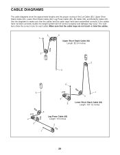
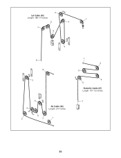
... proper routing of the Lat Cable (62), Upper Short Stack Cable (63), Lower Short Stack Cable (64), Leg Press Cable (65), Ab Cable (66), and Butterfly Cable (67). CABLE DIAGRAMS The cable diagrams show the correct route for each cable. Make sure that the cables and the cable traps have not...
... proper routing of the Lat Cable (62), Upper Short Stack Cable (63), Lower Short Stack Cable (64), Leg Press Cable (65), Ab Cable (66), and Butterfly Cable (67). CABLE DIAGRAMS The cable diagrams show the correct route for each cable. Make sure that the cables and the cable traps have not...
English Manual
Page 30
2 Lat Cable (62) Length: 188 1/4 inches 1 6 4 7 5 3 8 8 3 4 2 6 Ab Cable (66) Length: 217 inches 5 7 1 1 2 5 4 6 Butterfly Cable (67) Length: 107 1/2 inches 7 30
2 Lat Cable (62) Length: 188 1/4 inches 1 6 4 7 5 3 8 8 3 4 2 6 Ab Cable (66) Length: 217 inches 5 7 1 1 2 5 4 6 Butterfly Cable (67) Length: 107 1/2 inches 7 30
English Manual
Page 31
... stretch slightly when it is oriented to be replaced, see ORDERING REPLACEMENT PARTS on the back cover of the Leg Press Cable (65) or the Butterfly Cable (67). Reattach the Pulley and the Cable Trap between the indicated set of holes closer to remove the 4 100mm Pulley (38) from the cables...
... stretch slightly when it is oriented to be replaced, see ORDERING REPLACEMENT PARTS on the back cover of the Leg Press Cable (65) or the Butterfly Cable (67). Reattach the Pulley and the Cable Trap between the indicated set of holes closer to remove the 4 100mm Pulley (38) from the cables...
English Manual
Page 39
... Cap M12 Nut "T"-handle Leg Lever Bumper Leg Lever Lock Lat Cable Upper Short Stack Cable Lower Short Stack Cable Leg Press Cable Ab Cable Butterfly Cable Long Cable Trap 12.5mm Spacer M10 Thick Spacer Weight Bumper Ab Strap 16" Chain Ankle Strap Spring Clip 25mm Round Inner Cap Lat... Bar Butterfly Pin M10 Round Bushing M10 x 65mm Bolt M10 x 50mm Bolt M10 x 75mm Bolt M6 x 35mm Bolt M10 x 68mm Bolt M10 x 92mm Carriage Bolt M10 x 225mm...
... Cap M12 Nut "T"-handle Leg Lever Bumper Leg Lever Lock Lat Cable Upper Short Stack Cable Lower Short Stack Cable Leg Press Cable Ab Cable Butterfly Cable Long Cable Trap 12.5mm Spacer M10 Thick Spacer Weight Bumper Ab Strap 16" Chain Ankle Strap Spring Clip 25mm Round Inner Cap Lat... Bar Butterfly Pin M10 Round Bushing M10 x 65mm Bolt M10 x 50mm Bolt M10 x 75mm Bolt M6 x 35mm Bolt M10 x 68mm Bolt M10 x 92mm Carriage Bolt M10 x 225mm...


