
English Manual
Page 1
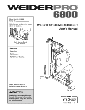
WEIGHT SYSTEM EXERCISER User’'s Manual Serial Number Decal (under the seat) •• Assembly •• Operation •• Maintenance •• Part List and Drawing Sears, Roebuck and Co. Keep this equipment. Model No. 831.14922.2 Serial No. Write the serial number in this manual before using this manual for reference. Hoffman Estates, IL 60179 CAUTION Read all precautions and instructions in the space above for future reference.
WEIGHT SYSTEM EXERCISER User’'s Manual Serial Number Decal (under the seat) •• Assembly •• Operation •• Maintenance •• Part List and Drawing Sears, Roebuck and Co. Keep this equipment. Model No. 831.14922.2 Serial No. Write the serial number in this manual before using this manual for reference. Hoffman Estates, IL 60179 CAUTION Read all precautions and instructions in the space above for future reference.
English Manual
Page 2
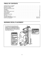
... 4 PART IDENTIFICATION CHART 5 ASSEMBLY 6 ADJUSTMENT 21 WEIGHT RESISTANCE CHART 23 CABLE DIAGRAM 24 MAINTENANCE 25 EXERCISE GUIDELINES 26 PART LIST 29 EXPLODED DRAWING 30 ORDERING REPLACEMENT PARTS Back Cover 90 DAY FULL WARRANTY Back Cover WARNING DECAL PLACEMENT This drawing shows the location(s) of the warning decal(s). If a decal is missing or illegible, call 1-877-992-5999 and request a free replacement decal. Note: The decal(s) may not be shown at actual size...
... 4 PART IDENTIFICATION CHART 5 ASSEMBLY 6 ADJUSTMENT 21 WEIGHT RESISTANCE CHART 23 CABLE DIAGRAM 24 MAINTENANCE 25 EXERCISE GUIDELINES 26 PART LIST 29 EXPLODED DRAWING 30 ORDERING REPLACEMENT PARTS Back Cover 90 DAY FULL WARRANTY Back Cover WARNING DECAL PLACEMENT This drawing shows the location(s) of the warning decal(s). If a decal is missing or illegible, call 1-877-992-5999 and request a free replacement decal. Note: The decal(s) may not be shown at actual size...
English Manual
Page 3
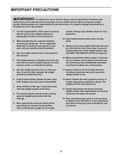
... are exercising, stop immediately and cool down. 3 Before beginning any worn parts immediately. 7. The weight system is the responsibility of the owner to tip. 6. Never release the arms, leg lever, lat bar, or handle strap while weights are on the foot plate when performing an exercise that all users of the weight system are adequately informed of this product. 1. The weights will fall with pre-existing health problems...
... are exercising, stop immediately and cool down. 3 Before beginning any worn parts immediately. 7. The weight system is the responsibility of the owner to tip. 6. Never release the arms, leg lever, lat bar, or handle strap while weights are on the foot plate when performing an exercise that all users of the weight system are adequately informed of this product. 1. The weights will fall with pre-existing health problems...
English Manual
Page 4
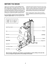
... WEIDER PRO® 6900 weight system. Before reading further, please review the drawing below and familiarize yourself with the parts that are used relative to right and left side”" are labeled. they do not correspond to a person sitting on the drawings in . (196 cm) High Pulley Station Arm Backrest Curl Pad Right Side Leg Lever Low Pulley Station Foot Plate Arm Pin...
... WEIDER PRO® 6900 weight system. Before reading further, please review the drawing below and familiarize yourself with the parts that are used relative to right and left side”" are labeled. they do not correspond to a person sitting on the drawings in . (196 cm) High Pulley Station Arm Backrest Curl Pad Right Side Leg Lever Low Pulley Station Foot Plate Arm Pin...
English Manual
Page 5
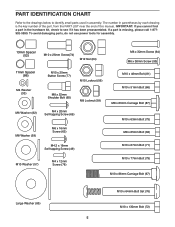
... PART IDENTIFICATION CHART Refer to the drawings below to see if it has been preassembled. If a part is the key number of the part, from the PART LIST near the end of this manual. To avoid damaging parts, do not use power tools for assembly. 13mm Spacer (52) M10 x 25mm Screw(74...Screw (62) M10 x 46mm Bolt (81) M10 x 51mm Bolt (66) M8 x 63mm Carriage Bolt (87) M10 x 63mm Bolt (75) M8 x 65mm Bolt (68) M4.2 x 16mm Self-tapping Screw (49) M10 x 67mm Bolt (71) M10 Washer (57) M4 x 12mm Screw (78) M10 x 77mm Bolt (79) M10 x 86mm Carriage Bolt (67) Large Washer (85) M10 x 64mm Bolt Set...
... PART IDENTIFICATION CHART Refer to the drawings below to see if it has been preassembled. If a part is the key number of the part, from the PART LIST near the end of this manual. To avoid damaging parts, do not use power tools for assembly. 13mm Spacer (52) M10 x 25mm Screw(74...Screw (62) M10 x 46mm Bolt (81) M10 x 51mm Bolt (66) M8 x 63mm Carriage Bolt (87) M10 x 63mm Bolt (75) M8 x 65mm Bolt (68) M4.2 x 16mm Self-tapping Screw (49) M10 x 67mm Bolt (71) M10 Washer (57) M4 x 12mm Screw (78) M10 x 77mm Bolt (79) M10 x 86mm Carriage Bolt (67) Large Washer (85) M10 x 64mm Bolt Set...
English Manual
Page 6
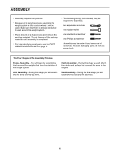
... attach the cables and pulleys that there is completed. •• For help identifying small parts, use power tools. Cable Assembly—-During this stage you will assemble the arms and the leg lever. ASSEMBLY •• Assembly requires two persons. •• Because of its weight and size, assemble the weight system in a cleared area and remove the packing materials. Make sure that connect the arms to walk around the weight...
... attach the cables and pulleys that there is completed. •• For help identifying small parts, use power tools. Cable Assembly—-During this stage you will assemble the arms and the leg lever. ASSEMBLY •• Assembly requires two persons. •• Because of its weight and size, assemble the weight system in a cleared area and remove the packing materials. Make sure that connect the arms to walk around the weight...
English Manual
Page 10
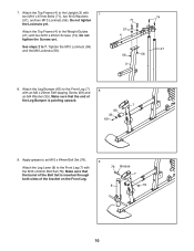
... to the Upright (3) with two M10 x 25mm Screws (74). Attach the Top Frame (4) to the Front Leg (7) with an M4 x 20mm Self-tapping Screw (69) and an M4 Washer (33). Apply grease to an M10 x 64mm Bolt Set (76). 9 Attach the Leg Lever (8) to the Weight Guides (21) with 7 two M10 x 67mm Bolts (71), ... of the Bolt Set is inserted through both sides of the Leg Bumper is pointing upward. 7 60 33 69 9. Do not tighten the Screws yet. Make sure that the end of the bracket on the Front Leg. 76 Grease 7 8 76 10 Attach the Leg Bumper (60) to 7. Tighten the M10 Locknuts...
... to the Upright (3) with two M10 x 25mm Screws (74). Attach the Top Frame (4) to the Front Leg (7) with an M4 x 20mm Self-tapping Screw (69) and an M4 Washer (33). Apply grease to an M10 x 64mm Bolt Set (76). 9 Attach the Leg Lever (8) to the Weight Guides (21) with 7 two M10 x 67mm Bolts (71), ... of the Bolt Set is inserted through both sides of the Leg Bumper is pointing upward. 7 60 33 69 9. Do not tighten the Screws yet. Make sure that the end of the bracket on the Front Leg. 76 Grease 7 8 76 10 Attach the Leg Bumper (60) to 7. Tighten the M10 Locknuts...

English Manual
Page 11
... x 20mm Self-tapping Screws (69). Apply grease to the Top Frame (4) with the M10 x 77mm Bolt (79) and an M10 Locknut (56). the Cable Pivot must pivot easily. 56 5 4 Grease 79 Arm Assembly 11 11. Attach a Handle (11) to the Left Arm (10) 12 9 with two M10 x 25mm Button Screws (77) and two M10 Washers (57). Insert the Arm Pins (40) into the...
... x 20mm Self-tapping Screws (69). Apply grease to the Top Frame (4) with the M10 x 77mm Bolt (79) and an M10 Locknut (56). the Cable Pivot must pivot easily. 56 5 4 Grease 79 Arm Assembly 11 11. Attach a Handle (11) to the Left Arm (10) 12 9 with two M10 x 25mm Button Screws (77) and two M10 Washers (57). Insert the Arm Pins (40) into the...

English Manual
Page 12
Attach the Left Arm (10) to identify the cables as you assemble them. See the CABLE DIAGRAM on page 24 to the Pivot Frame (5) with the M8 x 22mm Shoulder Bolt (65) and an M8 Locknut (58). 58 39 54 Grease 65 12 Identify the Arm Cable (54). Apply grease to two Arm Bushings (44). Apply grease to an M10 x 86mm Carriage Bolt 13 (67) and...
Attach the Left Arm (10) to identify the cables as you assemble them. See the CABLE DIAGRAM on page 24 to the Pivot Frame (5) with the M8 x 22mm Shoulder Bolt (65) and an M8 Locknut (58). 58 39 54 Grease 65 12 Identify the Arm Cable (54). Apply grease to two Arm Bushings (44). Apply grease to an M10 x 86mm Carriage Bolt 13 (67) and...

English Manual
Page 17
... Thick Pulley (48), a Small Cable Trap (51), and two Half Guards (43) to hold the High Cable (55) in step 26, an 11mm Spacer (86), an M10 Washer (57), and an M10 Locknut (56). 56 43 45 55 48 51 43 66 55 47 56 4 57 86 71 29. Make sure that the Small Cable... the M10 x 67mm Bolt (71) used in the groove of the Thick Pulley (48) and that the Half Guards (43) are on the outside of the U-bracket (45). 28. Route the High Cable (55) over a Thick Pulley 29 (48) and downward through the Top Frame (4) and over a Thin Pulley (47). 28 Attach the Thin Pulley (47) inside the Top...
... Thick Pulley (48), a Small Cable Trap (51), and two Half Guards (43) to hold the High Cable (55) in step 26, an 11mm Spacer (86), an M10 Washer (57), and an M10 Locknut (56). 56 43 45 55 48 51 43 66 55 47 56 4 57 86 71 29. Make sure that the Small Cable... the M10 x 67mm Bolt (71) used in the groove of the Thick Pulley (48) and that the Half Guards (43) are on the outside of the U-bracket (45). 28. Route the High Cable (55) over a Thick Pulley 29 (48) and downward through the Top Frame (4) and over a Thin Pulley (47). 28 Attach the Thin Pulley (47) inside the Top...

English Manual
Page 18
... x 38mm 32 Screw (95), and an M6 Washer (82). 15 Insert the Seat Frame (73) into the Seat Tube (6) and tighten a Long Knob (91) into the Weight Selector (24) until all the way onto the 30 High Cable (55). Thread an M12 Nut (84) all the slack is removed from the cables. Tighten the High Cable (55) into the Seat Tube and...
... x 38mm 32 Screw (95), and an M6 Washer (82). 15 Insert the Seat Frame (73) into the Seat Tube (6) and tighten a Long Knob (91) into the Weight Selector (24) until all the way onto the 30 High Cable (55). Thread an M12 Nut (84) all the slack is removed from the cables. Tighten the High Cable (55) into the Seat Tube and...
English Manual
Page 20
... Screws (49) and the M4 x 12mm Screws (78). 36. Before using the weight system, pull each cable a few times to remove the slack by tightening the cables. If there is any slack in ADJUSTMENT, beginning on page 21. Attach a Shroud Support (19) and the bottom of the cables does not move smoothly around the pulleys. See MAINTENANCE on page 24 for proper cable routing. Do not tighten the Screws...
... Screws (49) and the M4 x 12mm Screws (78). 36. Before using the weight system, pull each cable a few times to remove the slack by tightening the cables. If there is any slack in ADJUSTMENT, beginning on page 21. Attach a Shroud Support (19) and the bottom of the cables does not move smoothly around the pulleys. See MAINTENANCE on page 24 for proper cable routing. Do not tighten the Screws...
English Manual
Page 21
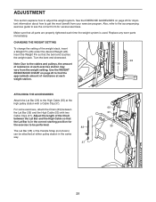
... The Lat Bar (35) or the Handle Strap (not shown) can be attached at either pulley station in the correct starting position for the exercise to find the approximate amount of resistance at the high pulley station with two Cable Clips (37). Insert the Weight Pin so that all parts are properly tightened each exercise station may vary from your exercise program. Also, refer to the accompanying exercise guide...
... The Lat Bar (35) or the Handle Strap (not shown) can be attached at either pulley station in the correct starting position for the exercise to find the approximate amount of resistance at the high pulley station with two Cable Clips (37). Insert the Weight Pin so that all parts are properly tightened each exercise station may vary from your exercise program. Also, refer to the accompanying exercise guide...

English Manual
Page 22
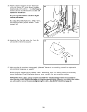
... use the Arms (9, 10) as press arms, insert the Arm Pins (40) into the holes in the Upright (3) as a footrest, rotate the Foot Plate downward so that does not require the Curl Pad (14), remove the Curl Pad and replace the 50mm Round Inner Cap (30) into the Front Leg (7). Store the Curl Pad away from the Front Leg (7). CONVERTING THE ARMS...
... use the Arms (9, 10) as press arms, insert the Arm Pins (40) into the holes in the Upright (3) as a footrest, rotate the Foot Plate downward so that does not require the Curl Pad (14), remove the Curl Pad and replace the 50mm Round Inner Cap (30) into the Front Leg (7). Store the Curl Pad away from the Front Leg (7). CONVERTING THE ARMS...
English Manual
Page 23
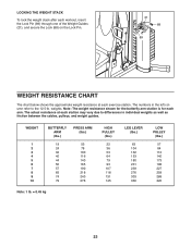
weights. Note: The weight resistance shown for the buttery arm station is for each exercise station. The actual resistance at each arm. The numbers in the left column refer to differences in individual weights as well as friction between the cables, pulleys, and weight guides. WEIGHT 1 2 3 4 5 6 7 8 9 10 BUTTERFLY ARM (lbs.) 19 24 32 40 44 50 57 65 74 79 PRESS ARM (lbs.) 53 78 100 116...
weights. Note: The weight resistance shown for the buttery arm station is for each exercise station. The actual resistance at each arm. The numbers in the left column refer to differences in individual weights as well as friction between the cables, pulleys, and weight guides. WEIGHT 1 2 3 4 5 6 7 8 9 10 BUTTERFLY ARM (lbs.) 19 24 32 40 44 50 57 65 74 79 PRESS ARM (lbs.) 53 78 100 116...
English Manual
Page 25
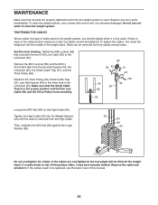
... M10 x 51mm Bolt (66) from the High Cable. do not use a damp cloth and a mild, non-abrasive detergent; Remove the cable and reinstall it may have become twisted. Replace any worn parts immediately. Tighten the High Cable (55) into the middle of the weight stack. If a cable tends to slip off the weight stack. If the cables need to be tightened. MAINTENANCE Make sure that connects the end...
... M10 x 51mm Bolt (66) from the High Cable. do not use a damp cloth and a mild, non-abrasive detergent; Remove the cable and reinstall it may have become twisted. Replace any worn parts immediately. Tighten the High Cable (55) into the middle of the weight stack. If a cable tends to slip off the weight stack. If the cables need to be tightened. MAINTENANCE Make sure that connects the end...
English Manual
Page 26
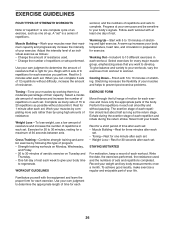
... parts of the body. Warming Up—-Start with the equipment and learn the proper form for each set ”" is a series of repetitions. To give your body temperature, heart rate, and circulation in each repetition and inhale during the return stroke. Weight Loss—-To lose weight, use a low amount of resistance and increase the number of rest. Cross Training—-Combine strength training and aerobic exercise...
... parts of the body. Warming Up—-Start with the equipment and learn the proper form for each set ”" is a series of repetitions. To give your body temperature, heart rate, and circulation in each repetition and inhale during the return stroke. Weight Loss—-To lose weight, use a low amount of resistance and increase the number of rest. Cross Training—-Combine strength training and aerobic exercise...
English Manual
Page 27
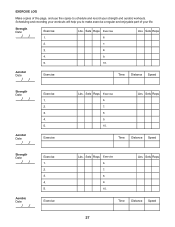
Sets Reps Exercise 6. Sets Reps Exercise 6. 7. 8. 9. 10. Aerobic Date: Exercise Time Distance Speed Strength Date: Aerobic Date: Exercise 1. 2. 3. 4. 5. Exercise Lbs. Sets Reps Time Distance Speed 27 Lbs. Lbs. Lbs. Exercise Lbs. EXERCISE LOG Make copies of your strength and aerobic workouts. Sets Reps Time Distance Speed Strength Date: Aerobic Date: Exercise 1. 2. 3. 4. 5. Sets Reps 2. 7. 3. 8. 4. 9. 5. 10. Scheduling and recording your workouts will help you to make exercise a regular and enjoyable part of this page, and use the...
Sets Reps Exercise 6. Sets Reps Exercise 6. 7. 8. 9. 10. Aerobic Date: Exercise Time Distance Speed Strength Date: Aerobic Date: Exercise 1. 2. 3. 4. 5. Exercise Lbs. Sets Reps Time Distance Speed 27 Lbs. Lbs. Lbs. Exercise Lbs. EXERCISE LOG Make copies of your strength and aerobic workouts. Sets Reps Time Distance Speed Strength Date: Aerobic Date: Exercise 1. 2. 3. 4. 5. Sets Reps 2. 7. 3. 8. 4. 9. 5. 10. Scheduling and recording your workouts will help you to make exercise a regular and enjoyable part of this page, and use the...
English Manual
Page 29
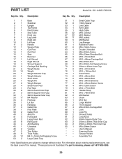
... Inner Cap 94 2 25mm x 40mm Thin Inner Cap 95 1 M6 x 38mm Screw * –- User’'s Manual * –- For information about ordering replacement parts, see the back cover of this manual. *These parts are subject to change without notice. Exercise Guide * –- If a part is missing, please call 1-877-992-5999. 29 Qty. Assembly Tool Note: Specifications are not illustrated. Qty. PART LIST Model No. 831.14922.2 R0912A Key No.
... Inner Cap 94 2 25mm x 40mm Thin Inner Cap 95 1 M6 x 38mm Screw * –- User’'s Manual * –- For information about ordering replacement parts, see the back cover of this manual. *These parts are subject to change without notice. Exercise Guide * –- If a part is missing, please call 1-877-992-5999. 29 Qty. Assembly Tool Note: Specifications are not illustrated. Qty. PART LIST Model No. 831.14922.2 R0912A Key No.

English Manual
Page 32
... when the Weight System Exerciser is used commercially or for free repair (or replacement if repair proves impossible). Sears, Roebuck and Co., Hoffman Estates, IL 60179 Part No. 338274 R0912A Printed in material or workmanship within 90 days of the date of purchase, call 1-800-4-MY-HOME® (1-800-469-4663) to arrange for rental purposes. This warranty gives you specific legal...
... when the Weight System Exerciser is used commercially or for free repair (or replacement if repair proves impossible). Sears, Roebuck and Co., Hoffman Estates, IL 60179 Part No. 338274 R0912A Printed in material or workmanship within 90 days of the date of purchase, call 1-800-4-MY-HOME® (1-800-469-4663) to arrange for rental purposes. This warranty gives you specific legal...


