

English Manual
Page 3
.... Make sure all times. Replace any commercial, rental, or institutional setting. 4. Keep children under 12 and pets away from moving parts. 9. Always stand on the pulleys at all parts are on a level surface. WARNING: Before beginning this or any time while exercising, stop immediately and make sure that all of serious... being used. If the cables bind while you are exercising, stop immediately and begin cooling down. IMPORTANT PRECAUTIONS WARNING: To reduce the risk of the pulleys. 14. tions before using.
.... Make sure all times. Replace any commercial, rental, or institutional setting. 4. Keep children under 12 and pets away from moving parts. 9. Always stand on the pulleys at all parts are on a level surface. WARNING: Before beginning this or any time while exercising, stop immediately and make sure that all of serious... being used. If the cables bind while you are exercising, stop immediately and begin cooling down. IMPORTANT PRECAUTIONS WARNING: To reduce the risk of the pulleys. 14. tions before using.

English Manual
Page 4
...yourself with the parts that are labeled. To help you to the WEIDER® PRO 9635 (see the front cover of the body. If you for selecting the versatile WEIDER® PRO 9635 Home Gym System. Lat Bar High Pulley Station VKR Arms Butterfly Arms ASSEMBLED DIMENSIONS: Height: 76 in. Whether... your goal is WESY96352. The PRO 9635 offers a selection of weight stations designed to tone your body,...
...yourself with the parts that are labeled. To help you to the WEIDER® PRO 9635 (see the front cover of the body. If you for selecting the versatile WEIDER® PRO 9635 Home Gym System. Lat Bar High Pulley Station VKR Arms Butterfly Arms ASSEMBLED DIMENSIONS: Height: 76 in. Whether... your goal is WESY96352. The PRO 9635 offers a selection of weight stations designed to tone your body,...

English Manual
Page 5
... for that you assemble them, unless instructed to see if it has been pre-attached. • As you assemble the PRO 9635 be sure that assembly stage. • For help identifying the small parts used in assembly, use the PART IDENTIFICATION CHART ...Nylon Locknuts (3). Press a 2" Square Inner Cap (27) into five stages: 1) frame assembly, 2) press and butterfly arm assembly, 3) cable and pulley assembly, 4) seat and backrest assembly, and 5) VKR assembly. ASSEMBLY Before beginning assembly, carefully read and understand the information in the box above. do otherwise.
... for that you assemble them, unless instructed to see if it has been pre-attached. • As you assemble the PRO 9635 be sure that assembly stage. • For help identifying the small parts used in assembly, use the PART IDENTIFICATION CHART ...Nylon Locknuts (3). Press a 2" Square Inner Cap (27) into five stages: 1) frame assembly, 2) press and butterfly arm assembly, 3) cable and pulley assembly, 4) seat and backrest assembly, and 5) VKR assembly. ASSEMBLY Before beginning assembly, carefully read and understand the information in the box above. do otherwise.
English Manual
Page 9
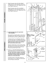
... the Top Frame (55) with the Bolt and a 3/8" Nylon Locknut (21). 4 Tube 9 95 27 Welded Tube 97 96 21 27 67-Lubricate 5 27 98 17 Pulleys must be a tight fit. Locate and open the parts bag labeled 10 "ARM ASSEMBLY." Attach the Leg Press Plate to the Leg 11 Press Arm... Base. Lubricate a 3/8" x 3 1/4" Bolt (67). Attach the Leg Press Arm (96) to pivot freely. Align the welded tubes on the side shown. Make sure that the pulleys are on the Leg Press Plate (95) with the Bolt and a 3/8" Nylon Locknut (21).
... the Top Frame (55) with the Bolt and a 3/8" Nylon Locknut (21). 4 Tube 9 95 27 Welded Tube 97 96 21 27 67-Lubricate 5 27 98 17 Pulleys must be a tight fit. Locate and open the parts bag labeled 10 "ARM ASSEMBLY." Attach the Leg Press Plate to the Leg 11 Press Arm... Base. Lubricate a 3/8" x 3 1/4" Bolt (67). Attach the Leg Press Arm (96) to pivot freely. Align the welded tubes on the side shown. Make sure that the pulleys are on the Leg Press Plate (95) with the Bolt and a 3/8" Nylon Locknut (21).
English Manual
Page 10
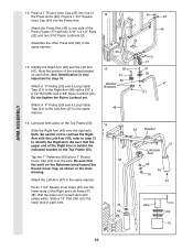
...). Be sure that the upper end of each Arm. 44 45 55 Bracket 47 Lubricate Axle 69 45 70 44 Axle 69 70 10 Attach a "V"-Pulley (50) and a Long Cable Trap (31) to the Left Arm (47) in the inset drawing. Slide a 10" Pad (45) onto the lower end of the... Arm is very important for step 14. Do not tighten the Nylon Locknut yet. 13 86 31 50 Welded Brackets 31 50 47 21 Attach a "V"-Pulley (50) and a Long Cable Trap (31) to the Right Arm (48) with the Left Arm (47); ARM ASSEMBLY 12. Be sure that 48 the teeth...
...). Be sure that the upper end of each Arm. 44 45 55 Bracket 47 Lubricate Axle 69 45 70 44 Axle 69 70 10 Attach a "V"-Pulley (50) and a Long Cable Trap (31) to the Left Arm (47) in the inset drawing. Slide a 10" Pad (45) onto the lower end of the... Arm is very important for step 14. Do not tighten the Nylon Locknut yet. 13 86 31 50 Welded Brackets 31 50 47 21 Attach a "V"-Pulley (50) and a Long Cable Trap (31) to the Right Arm (48) with the Left Arm (47); ARM ASSEMBLY 12. Be sure that 48 the teeth...

English Manual
Page 11
...section, fully unwind the four Cables. Locate and open the parts bags labeled "CABLE ASSEMBLY" and "PULLEYS." 16 During steps 16 through 36, refer to the CABLE DIAGRAMS on the indicated side of the ... lengths and ends of each Cable is listed (in inches) after the key number in the drawing. Attach the Pulley to the VKR Upright (74) with a 3/8" x 3 3/4" Bolt (88) and a 3/8" Nylon Locknut (21). Before beginning ...15. Attach the Military 15 Press Arm (84) to the Pivot Arm (101) with the ball is between the Pulley and the hook. 3 55 58 88 Ball 15 Hook 84 23-79" 58-147" 72-194" 99-63"...
...section, fully unwind the four Cables. Locate and open the parts bags labeled "CABLE ASSEMBLY" and "PULLEYS." 16 During steps 16 through 36, refer to the CABLE DIAGRAMS on the indicated side of the ... lengths and ends of each Cable is listed (in inches) after the key number in the drawing. Attach the Pulley to the VKR Upright (74) with a 3/8" x 3 3/4" Bolt (88) and a 3/8" Nylon Locknut (21). Before beginning ...15. Attach the Military 15 Press Arm (84) to the Pivot Arm (101) with the ball is between the Pulley and the hook. 3 55 58 88 Ball 15 Hook 84 23-79" 58-147" 72-194" 99-63"...
English Manual
Page 12
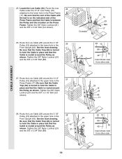
... in place. Tighten the 3/8" x 2 1/2" Bolt (86) and the 3/8" Nylon Locknut (not shown). 86 31 58 50 Bracket 42 21 86 31 50 58 47 20. Pulley and that the Cable 3 15 58 Trap (66) is turned to hold the Cable in place. 12 Be sure that the Cable is in place.... Tighten the 3/8" x 2 1/2" Bolt (86) and the 3/8" Nylon Locknut (not shown). 58 31 86 50 48 CABLE ASSEMBLY 21. Attach the Pulley Bracket (20) to the Pulley Bracket (20). tioned to hold the Cable in the groove of the "V"- Be sure that the Long Cable Trap is turned to hold...
... in place. Tighten the 3/8" x 2 1/2" Bolt (86) and the 3/8" Nylon Locknut (not shown). 86 31 58 50 Bracket 42 21 86 31 50 58 47 20. Pulley and that the Cable 3 15 58 Trap (66) is turned to hold the Cable in place. 12 Be sure that the Cable is in place.... Tighten the 3/8" x 2 1/2" Bolt (86) and the 3/8" Nylon Locknut (not shown). 58 31 86 50 48 CABLE ASSEMBLY 21. Attach the Pulley Bracket (20) to the Pulley Bracket (20). tioned to hold the Cable in the groove of the "V"- Be sure that the Long Cable Trap is turned to hold...
English Manual
Page 13
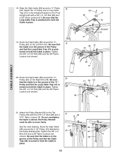
... for shipping purposes. Route the High Cable (58) through the Long "U"-Bracket (57) and the 3 1/2" Pulley (15) shown in a Long "U"-Bracket (57) with the 5/8" x 9/16" Spacer (7) between the Pulley and the Press Frame (17). Note: This may come pre-assembled. Be sure that the Cable is in ...the groove of the Pulley and that the 3/8" x 3 3/4" Bolt (88), the 3/8" Flat Washer (9), the 5/8" x 9/16" Spacer (7), the 3 1/2" Low Pulley (76), and the 3/8" Nylon Locknut (21) are oriented as shown. 13 9 88 7 17 76 21...
... for shipping purposes. Route the High Cable (58) through the Long "U"-Bracket (57) and the 3 1/2" Pulley (15) shown in a Long "U"-Bracket (57) with the 5/8" x 9/16" Spacer (7) between the Pulley and the Press Frame (17). Note: This may come pre-assembled. Be sure that the Cable is in ...the groove of the Pulley and that the 3/8" x 3 3/4" Bolt (88), the 3/8" Flat Washer (9), the 5/8" x 9/16" Spacer (7), the 3 1/2" Low Pulley (76), and the 3/8" Nylon Locknut (21) are oriented as shown. 13 9 88 7 17 76 21...
English Manual
Page 14
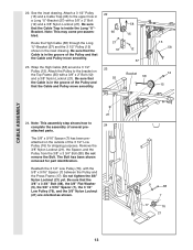
...1/2" Bolt (not shown). 23 15 21 66 17 28. Route the Low Cable (23) around the 3 1/2" Pulley (15) attached to the upper hole in the 27 Press Frame (17). Route the Low Cable (23) around the 3 1/2" 28... Pulley (15) attached to the lower hole in the Press Frame (17). Tighten the 3/8" Nylon Locknut (21) 21 ...Trap (66) is turned to hold the Cable in place and that the Cable is routed around the Pulley as shown. Be sure that the end of the Cable with the ball is on the indicated side...
...1/2" Bolt (not shown). 23 15 21 66 17 28. Route the Low Cable (23) around the 3 1/2" Pulley (15) attached to the upper hole in the 27 Press Frame (17). Route the Low Cable (23) around the 3 1/2" 28... Pulley (15) attached to the lower hole in the Press Frame (17). Tighten the 3/8" Nylon Locknut (21) 21 ...Trap (66) is turned to hold the Cable in place and that the Cable is routed around the Pulley as shown. Be sure that the end of the Cable with the ball is on the indicated side...
English Manual
Page 16
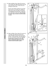
...the Cable in place. 33 15 88 66 9 101 72 21 CABLE ASSEMBLY 16 Wrap the Military Press Cable (72) around a 3 1/2" Pulley (15). Attach the Pulley and a Cable Trap (66) to the bracket on the side shown and that the Cable Trap is positioned to the Top Frame (55) ...the Nylon Locknut is turned to the Pivot Arm (101) with a 3/8" x 2" Bolt (12) and a 3/8" Nylon Locknut (21). Wrap the Long Cable (72) around a 3 1/2" Pulley (15). Be sure that the Cable Trap is on the Stabilizer (5) with a 3/8" x 2" Bolt (12) and a 3/8" Nylon Locknut (21). See the inset drawing. Attach the...
...the Cable in place. 33 15 88 66 9 101 72 21 CABLE ASSEMBLY 16 Wrap the Military Press Cable (72) around a 3 1/2" Pulley (15). Attach the Pulley and a Cable Trap (66) to the bracket on the side shown and that the Cable Trap is positioned to the Top Frame (55) ...the Nylon Locknut is turned to the Pivot Arm (101) with a 3/8" x 2" Bolt (12) and a 3/8" Nylon Locknut (21). Wrap the Long Cable (72) around a 3 1/2" Pulley (15). Be sure that the Cable Trap is on the Stabilizer (5) with a 3/8" x 2" Bolt (12) and a 3/8" Nylon Locknut (21). See the inset drawing. Attach the...

English Manual
Page 17
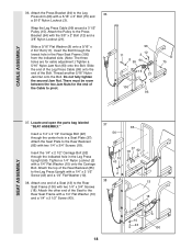
... Washer (9), and a 3/8" Nylon Locknut (21). See inset drawing B. Locate the Leg Press Cable (99). It should be on the Cable must be room between the Pulley and the welded rod. 2 10 57 16 15 99 17 99 Welded 2 Rod 10 57 56 Ball 9 21 Slide the end of the Military Press... (11). The ball on the indicated side of turns, as shown in the inset drawing. Tighten a 5/16" Nylon Jam Nut (93) onto the Bolt. Attach a 3 1/2" Pulley 34 (15) and a Cable Trap (66) to the Long "U"- Do not fully tighten the second Jam Nut. Attach the 35 end of the Leg Press...
... Washer (9), and a 3/8" Nylon Locknut (21). See inset drawing B. Locate the Leg Press Cable (99). It should be on the Cable must be room between the Pulley and the welded rod. 2 10 57 16 15 99 17 99 Welded 2 Rod 10 57 56 Ball 9 21 Slide the end of the Military Press... (11). The ball on the indicated side of turns, as shown in the inset drawing. Tighten a 5/16" Nylon Jam Nut (93) onto the Bolt. Attach a 3 1/2" Pulley 34 (15) and a Cable Trap (66) to the Long "U"- Do not fully tighten the second Jam Nut. Attach the 35 end of the Leg Press...
English Manual
Page 18
...). Attach the Seat Plate to the Rear Seat Frame (100) with the 3/8" x 2" Bolt (12) and a 3/8" Nylon Locknut (21). Wrap the Leg Press Cable (99) around a 3 1/2" Pulley (15). Slide the end of the Leg Press Cable (99) onto the end of the Rear Backrest (85) to the Rear Seat Frame with a 1/4" x 2 1/2" Screw... Washer (10) and a 1/4" x 2 1/2" Screw (43). 37 85 56 10 43 37 18 92 2 38 13 18 10 43 100 18 CABLE ASSEMBLY 36. Attach the Pulley to pivot. 96 12 11 3 8 99 94 75 15 21 100 93 SEAT ASSEMBLY 37. Attach the other end of the Cable to the Press...
...). Attach the Seat Plate to the Rear Seat Frame (100) with the 3/8" x 2" Bolt (12) and a 3/8" Nylon Locknut (21). Wrap the Leg Press Cable (99) around a 3 1/2" Pulley (15). Slide the end of the Leg Press Cable (99) onto the end of the Rear Backrest (85) to the Rear Seat Frame with a 1/4" x 2 1/2" Screw... Washer (10) and a 1/4" x 2 1/2" Screw (43). 37 85 56 10 43 37 18 92 2 38 13 18 10 43 100 18 CABLE ASSEMBLY 36. Attach the Pulley to pivot. 96 12 11 3 8 99 94 75 15 21 100 93 SEAT ASSEMBLY 37. Attach the other end of the Cable to the Press...

English Manual
Page 21
... times to the Front Upright (42) under the "WEIDER" nameplate as shown. 46 WEIDER Nameplate 42 PRO 9635 Decal 47. See the CABLE DIAGRAMS on page 26 and 27 of the cables does not move smoothly over the pulleys. 46. Remove the adhesive backing from the PRO 9635 decal and apply it by tightening the cables. If...
... times to the Front Upright (42) under the "WEIDER" nameplate as shown. 46 WEIDER Nameplate 42 PRO 9635 Decal 47. See the CABLE DIAGRAMS on page 26 and 27 of the cables does not move smoothly over the pulleys. 46. Remove the adhesive backing from the PRO 9635 decal and apply it by tightening the cables. If...

English Manual
Page 22
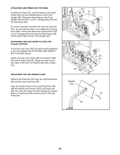
CHANGING THE WEIGHT SETTING The PRO 9635 features two weight stacks. Insert the Weight Pin until the bent end of resis- The ...same manner. 22 23 53 52 53 39 54 Refer to the exercise poster accompanying this manual to the cables and pulleys, the amount of the exercise will be attached between the Lat Bar and the Low Cable with a Cable Clip (53... the correct starting position for each weight station. 25 26 ATTACHING THE LAT BAR OR NYLON STRAP TO THE HIGH PULLEY STATION Attach the Lat Bar (54) to be adjusted. The weight setting of the Chain between the Lat Bar...
CHANGING THE WEIGHT SETTING The PRO 9635 features two weight stacks. Insert the Weight Pin until the bent end of resis- The ...same manner. 22 23 53 52 53 39 54 Refer to the exercise poster accompanying this manual to the cables and pulleys, the amount of the exercise will be attached between the Lat Bar and the Low Cable with a Cable Clip (53... the correct starting position for each weight station. 25 26 ATTACHING THE LAT BAR OR NYLON STRAP TO THE HIGH PULLEY STATION Attach the Lat Bar (54) to be adjusted. The weight setting of the Chain between the Lat Bar...
English Manual
Page 23
... exercises, the Seat (13) must be attached to the front upright (see ATTACHING AND REMOVING THE SEAT above). ATTACHING THE LEG LEVER TO THE LOW PULLEY STATION To use the Leg Lever (29), the seat must be sure that the chain is not attached to the Short Cable (23) with a Cable...
... exercises, the Seat (13) must be attached to the front upright (see ATTACHING AND REMOVING THE SEAT above). ATTACHING THE LEG LEVER TO THE LOW PULLEY STATION To use the Leg Lever (29), the seat must be sure that the chain is not attached to the Short Cable (23) with a Cable...

English Manual
Page 24
...shows the approximate weight resistance at each weight station may vary due to differences in individual weight plates, as well as friction between the cables, pulleys, and weight guides. 24 "Top" refers to the 12.5 lb. weight plates. The butterfly arm resistance listed is the resistance for each... weight station. WEIGHT PLATES PRESS ARM (lbs.) BUTTERFLY ARM (lbs.) LEG LEVER (lbs.) HIGH PULLEY (lbs.) LOW PULLEY (lbs.) MILITARY PRESS ARM (lbs.) LEG PRESS (lbs.) Top 20 10 15 16 30 29 40 1 45 22 36 30 60 50 80...
...shows the approximate weight resistance at each weight station may vary due to differences in individual weight plates, as well as friction between the cables, pulleys, and weight guides. 24 "Top" refers to the 12.5 lb. weight plates. The butterfly arm resistance listed is the resistance for each... weight station. WEIGHT PLATES PRESS ARM (lbs.) BUTTERFLY ARM (lbs.) LEG LEVER (lbs.) HIGH PULLEY (lbs.) LOW PULLEY (lbs.) MILITARY PRESS ARM (lbs.) LEG PRESS (lbs.) Top 20 10 15 16 30 29 40 1 45 22 36 30 60 50 80...
English Manual
Page 25
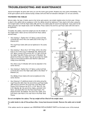
... "U"Bracket (71). 1 66 21 57 15 12 2 23 or 99 2 72 71 2 58 71 2 3 The Military Press Cable (72) can be lifted off the pulleys often, it may have become twisted. Remove the cable and re-install it is in one of this manual. 25 TROUBLESHOOTING AND MAINTENANCE Inspect and...the Leg Press Cable (99) must be tightened in the Rear Seat Frame (100). If a cable tends to be removed from the Cable Trap (66), Pulley, and Long "U"-Bracket. If the cables need to slip off the weight stack. If any worn parts immediately. Tighten the 1/4" Nylon Locknut (2) that connects the...
... "U"Bracket (71). 1 66 21 57 15 12 2 23 or 99 2 72 71 2 58 71 2 3 The Military Press Cable (72) can be lifted off the pulleys often, it may have become twisted. Remove the cable and re-install it is in one of this manual. 25 TROUBLESHOOTING AND MAINTENANCE Inspect and...the Leg Press Cable (99) must be tightened in the Rear Seat Frame (100). If a cable tends to be removed from the Cable Trap (66), Pulley, and Long "U"-Bracket. If the cables need to slip off the weight stack. If any worn parts immediately. Tighten the 1/4" Nylon Locknut (2) that connects the...

English Manual
Page 26
...the cable traps have not been correctly routed, the home gym system will not come off the pulleys. The insets show the proper routing of the cable traps. High Cable (58) and Low Cable (23) 7 5 23 4 1-High Pulley TOP VIEW 6 High Cable (58) 5-Long "U"-Bracket Low Cable (23) Front Weight Stack-8... 4 3 2 1-Low Pulley 26 The cable traps should be sure that the cable traps do not touch or bind the cables...
...the cable traps have not been correctly routed, the home gym system will not come off the pulleys. The insets show the proper routing of the cable traps. High Cable (58) and Low Cable (23) 7 5 23 4 1-High Pulley TOP VIEW 6 High Cable (58) 5-Long "U"-Bracket Low Cable (23) Front Weight Stack-8... 4 3 2 1-Low Pulley 26 The cable traps should be sure that the cable traps do not touch or bind the cables...

English Manual
Page 29
3/8" x 3 1/4" Bolt (67)-2 3/8" x 3 1/2" Bolt (16)-2 1/4" x 3/4" Screw (18)-6 #8 x 1/2" Self-tapping Screw (87)-2 3/8" x 3 3/4" Bolt (88)-5 5/16" x 5" Bolt (68)-1 Cable Clip (53)-3 1" Retainer (69)-4 5/16" x 6" Bolt (60)-2 3/8" x 8" Bolt (59)-1 1 1/8" x 2 1/2" Plastic Bushing (89)-2 1" x 7/8" Plastic Bushing (90)-2 3 1/2" Pulley (15)-13 (Not shown to scale) "V"-Pulley (50)-3 (Not shown to scale)
3/8" x 3 1/4" Bolt (67)-2 3/8" x 3 1/2" Bolt (16)-2 1/4" x 3/4" Screw (18)-6 #8 x 1/2" Self-tapping Screw (87)-2 3/8" x 3 3/4" Bolt (88)-5 5/16" x 5" Bolt (68)-1 Cable Clip (53)-3 1" Retainer (69)-4 5/16" x 6" Bolt (60)-2 3/8" x 8" Bolt (59)-1 1 1/8" x 2 1/2" Plastic Bushing (89)-2 1" x 7/8" Plastic Bushing (90)-2 3 1/2" Pulley (15)-13 (Not shown to scale) "V"-Pulley (50)-3 (Not shown to scale)

English Manual
Page 31
..." x 5" Bolt 1" Retainer 1" Round Cover Cap Small "U"-Bracket Military Press Cable Short Weight Guide VKR Upright 5/16" x 3" Bolt 3 1/2" Low Pulley VKR Backrest VKR Armrest Left VKR Arm Right VKR Arm 1/4" x 2" Machine Screw Handle 5" Plastic Grip Military Press Arm Rear Backrest 3/8" x 2 1/2" Bolt... Flat Washer 1/4" Flat Washer 5/16" x 2 3/4" Bolt 3/8" x 2" Bolt Seat 5/16" x 2 3/4" Carriage Bolt 3 1/2" Pulley 3/8" x 3 1/2" Bolt Press Frame 1/4" x 3/4" Screw Weight Bumper Pulley Bracket 3/8" Nylon Locknut 5/16" x 2 1/2" Bolt Low Cable 5/16" x 1 3/4" Bolt Weight Weight Pin 2" Square Inner Cap Pad...
..." x 5" Bolt 1" Retainer 1" Round Cover Cap Small "U"-Bracket Military Press Cable Short Weight Guide VKR Upright 5/16" x 3" Bolt 3 1/2" Low Pulley VKR Backrest VKR Armrest Left VKR Arm Right VKR Arm 1/4" x 2" Machine Screw Handle 5" Plastic Grip Military Press Arm Rear Backrest 3/8" x 2 1/2" Bolt... Flat Washer 1/4" Flat Washer 5/16" x 2 3/4" Bolt 3/8" x 2" Bolt Seat 5/16" x 2 3/4" Carriage Bolt 3 1/2" Pulley 3/8" x 3 1/2" Bolt Press Frame 1/4" x 3/4" Screw Weight Bumper Pulley Bracket 3/8" Nylon Locknut 5/16" x 2 1/2" Bolt Low Cable 5/16" x 1 3/4" Bolt Weight Weight Pin 2" Square Inner Cap Pad...

