

English Manual
Page 3
...beneath the home gym system to ensure that could become pinched between the leg press upright and military press arm. 13. Always stand on the pulleys at all times. Make sure all parts are raised. Your hand could cause the home gym system to tip. 12. IMPORTANT PRECAUTIONS WARNING: ... only on all instructions before using the home gym system. 1. The weights will fall with pre-existing health problems. Read all of the pulleys. 14. If you are exercising, stop immediately and begin cooling down. This is the responsibility of the owner to protect the floor. 5.
...beneath the home gym system to ensure that could become pinched between the leg press upright and military press arm. 13. Always stand on the pulleys at all times. Make sure all parts are raised. Your hand could cause the home gym system to tip. 12. IMPORTANT PRECAUTIONS WARNING: ... only on all instructions before using the home gym system. 1. The weights will fall with pre-existing health problems. Read all of the pulleys. 14. If you are exercising, stop immediately and begin cooling down. This is the responsibility of the owner to protect the floor. 5.

English Manual
Page 4
... Department toll-free at 1-800-9993756, Monday through Friday, 6 a.m. until 6 p.m. Width: 89 in . The PRO 9635 offers a selection of weight stations designed to the WEIDER® PRO 9635 (see the front cover of the body. The serial number can be found on a decal attached to develop every ...major muscle group of this manual carefully before calling. For your cardiovascular system, the PRO 9635 will help us assist you want. Lat Bar High Pulley...
... Department toll-free at 1-800-9993756, Monday through Friday, 6 a.m. until 6 p.m. Width: 89 in . The PRO 9635 offers a selection of weight stations designed to the WEIDER® PRO 9635 (see the front cover of the body. The serial number can be found on a decal attached to develop every ...major muscle group of this manual carefully before calling. For your cardiovascular system, the PRO 9635 will help us assist you want. Lat Bar High Pulley...

English Manual
Page 5
...indicated locations on the Stabilizer (5). Press a 2" Square Inner Cap (27) into five stages: 1) frame assembly, 2) press and butterfly arm assembly, 3) cable and pulley assembly, 4) seat and backrest assembly, and 5) VKR assembly. Insert two 5/16" x 2 1/2" Carriage Bolts up through the Base (4). If a part is ...small parts may have read the following tools: A socket set, a set of open-end or closed-end wrenches, or a set of the PRO 9635 in a cleared area and remove the packing materials; THE FOLLOWING TOOLS (NOT INCLUDED) ARE REQUIRED FOR ASSEMBLY: • Two (2) adjustable wrenches &#...
...indicated locations on the Stabilizer (5). Press a 2" Square Inner Cap (27) into five stages: 1) frame assembly, 2) press and butterfly arm assembly, 3) cable and pulley assembly, 4) seat and backrest assembly, and 5) VKR assembly. Insert two 5/16" x 2 1/2" Carriage Bolts up through the Base (4). If a part is ...small parts may have read the following tools: A socket set, a set of open-end or closed-end wrenches, or a set of the PRO 9635 in a cleared area and remove the packing materials; THE FOLLOWING TOOLS (NOT INCLUDED) ARE REQUIRED FOR ASSEMBLY: • Two (2) adjustable wrenches &#...
English Manual
Page 9
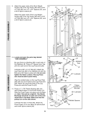
... Leg Press Plate (95) with the Bolt and a 3/8" Nylon Locknut (21). 4 Tube 9 95 27 Welded Tube 97 96 21 27 67-Lubricate 5 27 98 17 Pulleys must be able to the Top Frame (55) with the Press Pin (97). 11. Note: This will be on each side of the Long Weight... Guides (62) to pivot freely. Lubricate a 3/8" x 3 1/4" Bolt (67). Make sure that the pulleys are on the Press Frame (17). Attach the upper ends of the Leg Press Arm (96). Locate and open the parts bag labeled 10 "ARM...
... Leg Press Plate (95) with the Bolt and a 3/8" Nylon Locknut (21). 4 Tube 9 95 27 Welded Tube 97 96 21 27 67-Lubricate 5 27 98 17 Pulleys must be able to the Top Frame (55) with the Press Pin (97). 11. Note: This will be on each side of the Long Weight... Guides (62) to pivot freely. Lubricate a 3/8" x 3 1/4" Bolt (67). Make sure that the pulleys are on the Press Frame (17). Attach the upper ends of the Leg Press Arm (96). Locate and open the parts bag labeled 10 "ARM...
English Manual
Page 10
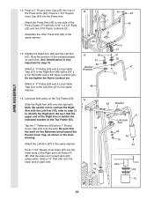
... welded bracket on the Top Frame (55). Do not tighten the Nylon Locknut yet. 13 86 31 50 Welded Brackets 31 50 47 21 Attach a "V"-Pulley (50) and a Long Cable Trap (31) to identify the Right Arm. refer to step 13 to the Left Arm (47) in the inset drawing. Tap... the other Press Arm (46) in the same manner. Wet the lower end of the 46 Press Frame (17) with the Left Arm (47); Attach a "V"-Pulley (50) and a Long Cable Trap (31) to the Right Arm (48) with soapy water. Attach the Left Arm (47) in the same manner. 46 3 17...
... welded bracket on the Top Frame (55). Do not tighten the Nylon Locknut yet. 13 86 31 50 Welded Brackets 31 50 47 21 Attach a "V"-Pulley (50) and a Long Cable Trap (31) to identify the Right Arm. refer to step 13 to the Left Arm (47) in the inset drawing. Tap... the other Press Arm (46) in the same manner. Wet the lower end of the 46 Press Frame (17) with the Left Arm (47); Attach a "V"-Pulley (50) and a Long Cable Trap (31) to the Right Arm (48) with soapy water. Attach the Left Arm (47) in the same manner. 46 3 17...

English Manual
Page 11
... two 1" Round Inner Caps (49) into the indicated end of each Cable is listed (in inches) after the key number in the drawing. Attach the Pulley to verify proper cable routing. Attach the Military Press Arm (84) to the Pivot Arm (101) with a 3/8" x 3 3/4" Bolt (88) and a 3/8" Nylon Locknut (21). 15. See... ARM ASSEMBLY CABLE ASSEMBLY 33 101 16. Attach the Military 15 Press Arm (84) to the VKR Upright (74) with the ball is between the Pulley and the hook. 3 55 58 88 Ball 15 Hook 84 23-79" 58-147" 72-194" 99-63" 11 Identify the four Cables by comparing...
... two 1" Round Inner Caps (49) into the indicated end of each Cable is listed (in inches) after the key number in the drawing. Attach the Pulley to verify proper cable routing. Attach the Military Press Arm (84) to the Pivot Arm (101) with a 3/8" x 3 3/4" Bolt (88) and a 3/8" Nylon Locknut (21). 15. See... ARM ASSEMBLY CABLE ASSEMBLY 33 101 16. Attach the Military 15 Press Arm (84) to the VKR Upright (74) with the ball is between the Pulley and the hook. 3 55 58 88 Ball 15 Hook 84 23-79" 58-147" 72-194" 99-63" 11 Identify the four Cables by comparing...
English Manual
Page 12
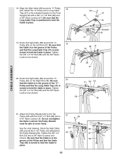
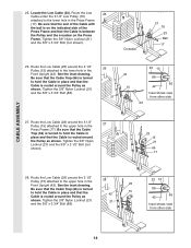
... 2 1/2" Bolt (86) and a 3/8" Nylon Locknut (21). Tighten the 3/8" x 2" 20 12 Bolt (12) and a 3/8" Nylon Locknut (not shown). Wrap the High Cable (58) around the "V"Pulley (50) on the Left Arm (47). Be sure that the Long Cable Trap is positioned to the indicated bracket on the Right Arm (48). Attach... the "V"-Pulley and a Long Cable Trap (31) to hold the Cable in the groove of the "V"- Be sure that the Cable is in place. Tighten the ...
... 2 1/2" Bolt (86) and a 3/8" Nylon Locknut (21). Tighten the 3/8" x 2" 20 12 Bolt (12) and a 3/8" Nylon Locknut (not shown). Wrap the High Cable (58) around the "V"Pulley (50) on the Left Arm (47). Be sure that the Long Cable Trap is positioned to the indicated bracket on the Right Arm (48). Attach... the "V"-Pulley and a Long Cable Trap (31) to hold the Cable in the groove of the "V"- Be sure that the Cable is in place. Tighten the ...
English Manual
Page 13
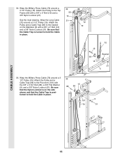
...) and a 3/8" Nylon Locknut (21). See the inset drawing. Remove the 3/8" Nylon Locknut (21), the Spacer, and the Pulley from the 3/8" x 3 3/4" Bolt (88). Note: This may come pre-assembled. Attach the Pulley to the upper hole in the groove of several pre- 24 attached parts. Do not tighten the 3/8" Nylon Locknut...is inside the Long "U"Bracket. Route the High Cable (58) through the Long "U"-Bracket (57) and the 3 1/2" Pulley (15) shown in the groove of the 3 1/2" Low Pulley (76) for part identification. Be sure that the Cable Trap is in the inset drawing. Wrap the High Cable (58...
...) and a 3/8" Nylon Locknut (21). See the inset drawing. Remove the 3/8" Nylon Locknut (21), the Spacer, and the Pulley from the 3/8" x 3 3/4" Bolt (88). Note: This may come pre-assembled. Attach the Pulley to the upper hole in the groove of several pre- 24 attached parts. Do not tighten the 3/8" Nylon Locknut...is inside the Long "U"Bracket. Route the High Cable (58) through the Long "U"-Bracket (57) and the 3 1/2" Pulley (15) shown in the groove of the 3 1/2" Low Pulley (76) for part identification. Be sure that the Cable Trap is in the inset drawing. Wrap the High Cable (58...
English Manual
Page 14
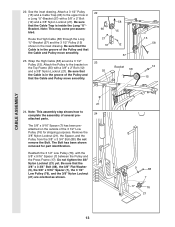
... (21) and the 3/8" x 3 1/2" Bolt (not shown). 23 15 21 66 17 28. Locate the Low Cable (23). Route the Low Cable (23) around the 3 1/2" Pulley (15) attached to hold the Cable in the Front Upright (42). Crossbar 21 76 23 Ball 17 26. Route the Low Cable (23) around the... Inset shows view from other side 14 Be sure that the end of the Press Frame and that the Cable is routed around the 3 1/2" 28 Pulley (15) attached to the lower hole in the Front Upright (42). Tighten the 3/8" Nylon Locknut (21) and the 3/8" x 3 3/4" Bolt (not shown). Be sure that...
... (21) and the 3/8" x 3 1/2" Bolt (not shown). 23 15 21 66 17 28. Locate the Low Cable (23). Route the Low Cable (23) around the 3 1/2" Pulley (15) attached to hold the Cable in the Front Upright (42). Crossbar 21 76 23 Ball 17 26. Route the Low Cable (23) around the... Inset shows view from other side 14 Be sure that the end of the Press Frame and that the Cable is routed around the 3 1/2" 28 Pulley (15) attached to the lower hole in the Front Upright (42). Tighten the 3/8" Nylon Locknut (21) and the 3/8" x 3 3/4" Bolt (not shown). Be sure that...
English Manual
Page 16
...15 88 66 9 101 72 21 CABLE ASSEMBLY 16 Wrap the Military Press Cable (72) around a 3 1/2" Pulley (15). Wrap the Military Press Cable (72) around a 3 1/2" Pulley (15). Wrap the Long Cable (72) around a 3 1/2" Pulley (15). Be sure that the Nylon Locknut is turned to the bracket on the side shown and that... the Cable Trap is on the Stabilizer (5) with a 3/8" x 2" Bolt (12) and a 3/8" Nylon Locknut (21). Attach the Pulley and a Cable Trap (66) to hold the Cable in place. 32 55 15 21 12 72 72 12 66 15 Bracket 21 5 33. Attach the...
...15 88 66 9 101 72 21 CABLE ASSEMBLY 16 Wrap the Military Press Cable (72) around a 3 1/2" Pulley (15). Wrap the Military Press Cable (72) around a 3 1/2" Pulley (15). Wrap the Long Cable (72) around a 3 1/2" Pulley (15). Be sure that the Nylon Locknut is turned to the bracket on the side shown and that... the Cable Trap is on the Stabilizer (5) with a 3/8" x 2" Bolt (12) and a 3/8" Nylon Locknut (21). Attach the Pulley and a Cable Trap (66) to hold the Cable in place. 32 55 15 21 12 72 72 12 66 15 Bracket 21 5 33. Attach the...

English Manual
Page 17
...: This may come pre- See inset drawing B. Do not completely tighten the Nylon Locknut. Be sure that the Cable and Pulley move smoothly and that the Cable and Pulley move smoothly. assembled.) Route the Military Press Cable (72) through the Pivot Arm (101) from the indicated side. Be...57) with a 3/8" x 2" Bolt (12) and a 3/8" Nylon Locknut (21). Slide a 5/16" Flat Washer (8) onto a 5/16" x 2 3/4 Bolt (11). There must be room between the Pulley and the welded rod. 2 10 57 16 15 99 17 99 Welded 2 Rod 10 57 56 Ball 9 21 Slide the end of the Military Press...
...: This may come pre- See inset drawing B. Do not completely tighten the Nylon Locknut. Be sure that the Cable and Pulley move smoothly and that the Cable and Pulley move smoothly. assembled.) Route the Military Press Cable (72) through the Pivot Arm (101) from the indicated side. Be...57) with a 3/8" x 2" Bolt (12) and a 3/8" Nylon Locknut (21). Slide a 5/16" Flat Washer (8) onto a 5/16" x 2 3/4 Bolt (11). There must be room between the Pulley and the welded rod. 2 10 57 16 15 99 17 99 Welded 2 Rod 10 57 56 Ball 9 21 Slide the end of the Military Press...
English Manual
Page 18
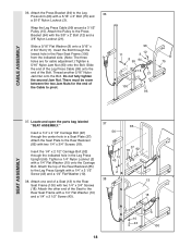
...: The three holes are for the end of the Cable to the Press Bracket (94) with the 3/8" x 2" Bolt (12) and a 3/8" Nylon Locknut (21). Attach the Pulley to pivot. 96 12 11 3 8 99 94 75 15 21 100 93 SEAT ASSEMBLY 37. Slide the end of the Leg Press Cable (99) onto... the Press Bracket (94) to the Rear Seat Frame (100) with a 5/16" x 3" Bolt (75) and a 5/16" Nylon Locknut (3). Wrap the Leg Press Cable (99) around a 3 1/2" Pulley (15). Attach the Seat Plate to the Leg Press Upright with two 1/4" x 3/4" Screws (18). Attach the top of a Seat (13) to the Leg 36 Press...
...: The three holes are for the end of the Cable to the Press Bracket (94) with the 3/8" x 2" Bolt (12) and a 3/8" Nylon Locknut (21). Attach the Pulley to pivot. 96 12 11 3 8 99 94 75 15 21 100 93 SEAT ASSEMBLY 37. Slide the end of the Leg Press Cable (99) onto... the Press Bracket (94) to the Rear Seat Frame (100) with a 5/16" x 3" Bolt (75) and a 5/16" Nylon Locknut (3). Wrap the Leg Press Cable (99) around a 3 1/2" Pulley (15). Attach the Seat Plate to the Leg Press Upright with two 1/4" x 3/4" Screws (18). Attach the top of a Seat (13) to the Leg 36 Press...

English Manual
Page 21
... for proper cable routing. Before using the home gym system, pull each cable a few times to the Front Upright (42) under the "WEIDER" nameplate as shown. 46 WEIDER Nameplate 42 PRO 9635 Decal 47. Make sure that the cables move smoothly, find and correct the problem. IMPORTANT: If the cables are not properly installed... remove it to be explained in the cables, you will be sure that all parts have been properly tightened. Remove the adhesive backing from the PRO 9635 decal and apply it by tightening the cables. The use of the cables does not move smoothly over the...
... for proper cable routing. Before using the home gym system, pull each cable a few times to the Front Upright (42) under the "WEIDER" nameplate as shown. 46 WEIDER Nameplate 42 PRO 9635 Decal 47. Make sure that the cables move smoothly, find and correct the problem. IMPORTANT: If the cables are not properly installed... remove it to be explained in the cables, you will be sure that all parts have been properly tightened. Remove the adhesive backing from the PRO 9635 decal and apply it by tightening the cables. The use of the cables does not move smoothly over the...

English Manual
Page 22
... insert a Weight Pin (26) under the desired Weight (25). The Nylon Strap (39) can be changed from the weight setting. CHANGING THE WEIGHT SETTING The PRO 9635 features two weight stacks. The weight setting of the exercise will be attached between the Lat Bar and the High Cable so the Lat Bar... to 106.5 pounds, in increments of the home gym system can be attached in the correct starting position for the exercise to the cables and pulleys, the amount of the Chain between the Lat Bar and the Low Cable with a Cable Clip (53). For some exercises, the Chain (52) should...
... insert a Weight Pin (26) under the desired Weight (25). The Nylon Strap (39) can be changed from the weight setting. CHANGING THE WEIGHT SETTING The PRO 9635 features two weight stacks. The weight setting of the exercise will be attached between the Lat Bar and the High Cable so the Lat Bar... to 106.5 pounds, in increments of the home gym system can be attached in the correct starting position for the exercise to the cables and pulleys, the amount of the Chain between the Lat Bar and the Low Cable with a Cable Clip (53). For some exercises, the Chain (52) should...
English Manual
Page 23
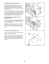
...) and the 5/16" x 2 3/4" Carriage Bolt (14) from the Leg Press Plate (95) and the Leg Press Arm (96). ATTACHING THE LEG LEVER TO THE LOW PULLEY STATION To use the Leg Lever (29), the seat must be removed. Attach one end of the Chain to the 3/8" x 2" Eyebolt (35) with a Cable Clip...
...) and the 5/16" x 2 3/4" Carriage Bolt (14) from the Leg Press Plate (95) and the Leg Press Arm (96). ATTACHING THE LEG LEVER TO THE LOW PULLEY STATION To use the Leg Lever (29), the seat must be removed. Attach one end of the Chain to the 3/8" x 2" Eyebolt (35) with a Cable Clip...

English Manual
Page 24
"Top" refers to differences in individual weight plates, as well as friction between the cables, pulleys, and weight guides. 24 WEIGHT PLATES PRESS ARM (lbs.) BUTTERFLY ARM (lbs.) LEG LEVER (lbs.) HIGH PULLEY (lbs.) LOW PULLEY (lbs.) MILITARY PRESS ARM (lbs.) LEG PRESS (lbs.) Top 20 10 15 16 30 29 40 1 45 22...
"Top" refers to differences in individual weight plates, as well as friction between the cables, pulleys, and weight guides. 24 WEIGHT PLATES PRESS ARM (lbs.) BUTTERFLY ARM (lbs.) LEG LEVER (lbs.) HIGH PULLEY (lbs.) LOW PULLEY (lbs.) MILITARY PRESS ARM (lbs.) LEG PRESS (lbs.) Top 20 10 15 16 30 29 40 1 45 22...
English Manual
Page 25
...weight stack, both 5/16" Nylon Jam Nuts (93) from these cables several ways: • See drawing 1. Tighten the 1/4" Nylon Locknut (2) that the Cable and Pulley move smoothly. If additional slack is in the Rear Seat Frame (100). Remove the 5/16" x 2 3/4" Bolt (11), the 5/16" Washer (8), the end of... Inspect and tighten all parts each time you use solvents. If there is slack in the same manner. • See drawing 1. Move the 3 1/2" Pulley (15) to the other Long "U"-Bracket (57) can be moved to be tightened. If any worn parts immediately. Remove the 3/8" Nylon Locknut (21)...
...weight stack, both 5/16" Nylon Jam Nuts (93) from these cables several ways: • See drawing 1. Tighten the 1/4" Nylon Locknut (2) that the Cable and Pulley move smoothly. If additional slack is in the Rear Seat Frame (100). Remove the 5/16" x 2 3/4" Bolt (11), the 5/16" Washer (8), the end of... Inspect and tighten all parts each time you use solvents. If there is slack in the same manner. • See drawing 1. Move the 3 1/2" Pulley (15) to the other Long "U"-Bracket (57) can be moved to be tightened. If any worn parts immediately. Remove the 3/8" Nylon Locknut (21)...

English Manual
Page 26
... cables have been assembled correctly. High Cable (58) and Low Cable (23) 7 5 23 4 1-High Pulley TOP VIEW 6 High Cable (58) 5-Long "U"-Bracket Low Cable (23) Front Weight Stack-8 4 3 2 1-Low Pulley 26 CABLE DIAGRAMS The cable diagrams on these pages show the proper positioning of the High Cable (58), the Low... sure that the four cables and the cable traps have not been correctly routed, the home gym system will not come off the pulleys. The insets show the proper routing of the cable traps. Be sure that the cables will not function properly and damage may occur.
... cables have been assembled correctly. High Cable (58) and Low Cable (23) 7 5 23 4 1-High Pulley TOP VIEW 6 High Cable (58) 5-Long "U"-Bracket Low Cable (23) Front Weight Stack-8 4 3 2 1-Low Pulley 26 CABLE DIAGRAMS The cable diagrams on these pages show the proper positioning of the High Cable (58), the Low... sure that the four cables and the cable traps have not been correctly routed, the home gym system will not come off the pulleys. The insets show the proper routing of the cable traps. Be sure that the cables will not function properly and damage may occur.

English Manual
Page 29
3/8" x 3 1/4" Bolt (67)-2 3/8" x 3 1/2" Bolt (16)-2 1/4" x 3/4" Screw (18)-6 #8 x 1/2" Self-tapping Screw (87)-2 3/8" x 3 3/4" Bolt (88)-5 5/16" x 5" Bolt (68)-1 Cable Clip (53)-3 1" Retainer (69)-4 5/16" x 6" Bolt (60)-2 3/8" x 8" Bolt (59)-1 1 1/8" x 2 1/2" Plastic Bushing (89)-2 1" x 7/8" Plastic Bushing (90)-2 3 1/2" Pulley (15)-13 (Not shown to scale) "V"-Pulley (50)-3 (Not shown to scale)
3/8" x 3 1/4" Bolt (67)-2 3/8" x 3 1/2" Bolt (16)-2 1/4" x 3/4" Screw (18)-6 #8 x 1/2" Self-tapping Screw (87)-2 3/8" x 3 3/4" Bolt (88)-5 5/16" x 5" Bolt (68)-1 Cable Clip (53)-3 1" Retainer (69)-4 5/16" x 6" Bolt (60)-2 3/8" x 8" Bolt (59)-1 1 1/8" x 2 1/2" Plastic Bushing (89)-2 1" x 7/8" Plastic Bushing (90)-2 3 1/2" Pulley (15)-13 (Not shown to scale) "V"-Pulley (50)-3 (Not shown to scale)

English Manual
Page 31
... Nylon Strap Seat Knob Front Backrest Front Upright 1/4" x 2 1/2" Screw 1 3/4" Square Inner Cap 10" Pad Press Arm Left Arm Right Arm 1" Round Inner Cap "V"-Pulley 2" Square Outer Cap Chain Key No. Qty. 53 3 54 1 55 1 56 1 57 2 58 1 59 1 60 2 61 4 62 2 63 2 ...1/4" Bolt 5/16" x 5" Bolt 1" Retainer 1" Round Cover Cap Small "U"-Bracket Military Press Cable Short Weight Guide VKR Upright 5/16" x 3" Bolt 3 1/2" Low Pulley VKR Backrest VKR Armrest Left VKR Arm Right VKR Arm 1/4" x 2" Machine Screw Handle 5" Plastic Grip Military Press Arm Rear Backrest 3/8" x 2 1/2" Bolt #8 x ...
... Nylon Strap Seat Knob Front Backrest Front Upright 1/4" x 2 1/2" Screw 1 3/4" Square Inner Cap 10" Pad Press Arm Left Arm Right Arm 1" Round Inner Cap "V"-Pulley 2" Square Outer Cap Chain Key No. Qty. 53 3 54 1 55 1 56 1 57 2 58 1 59 1 60 2 61 4 62 2 63 2 ...1/4" Bolt 5/16" x 5" Bolt 1" Retainer 1" Round Cover Cap Small "U"-Bracket Military Press Cable Short Weight Guide VKR Upright 5/16" x 3" Bolt 3 1/2" Low Pulley VKR Backrest VKR Armrest Left VKR Arm Right VKR Arm 1/4" x 2" Machine Screw Handle 5" Plastic Grip Military Press Arm Rear Backrest 3/8" x 2 1/2" Bolt #8 x ...

