
English Manual
Page 1
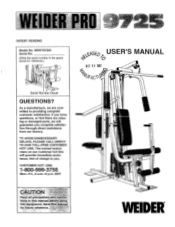
..., free of charge to providing complete customer satisfaction. PATENT PENDING Model No. If you have questions, or find there are missing or damaged parts, we are committed to you complete satisfaction through direct assistance from our factory. Save tills manual for reference.) 0 Serial Number Decal QUESTIONS? tions in the space above for future reference. • WEIDER MST 40E0 USER'S MANUAL )6 OCT...
..., free of charge to providing complete customer satisfaction. PATENT PENDING Model No. If you have questions, or find there are missing or damaged parts, we are committed to you complete satisfaction through direct assistance from our factory. Save tills manual for reference.) 0 Serial Number Decal QUESTIONS? tions in the space above for future reference. • WEIDER MST 40E0 USER'S MANUAL )6 OCT...
English Manual
Page 2
...:allPi:the pulleys. 13 AlWa.07diaConneCffthelat bar from-thaliome avmeYsteiii:when performing an exercise 14. TABLE OF CONTENTS IMPORTANT PRECAUTIONS BEFORE YOU BEGIN ASSEMBLY ADJUSTMENT TROUBLE-SHOOTING AND MAINTENANCE CABLE DIAGRAM ORDERING REPLACEMENT PARTS LIMITED WARRANTY 2 3 4 19 22 23 Back Cover Back Cover Note: An EXPLODED DRAWING/PART LIST and a PART IDENTIFICATION CHART are raised. The weights will fall with great force. 4. Always wear athletic shoes for home ,use not use of serious...
...:allPi:the pulleys. 13 AlWa.07diaConneCffthelat bar from-thaliome avmeYsteiii:when performing an exercise 14. TABLE OF CONTENTS IMPORTANT PRECAUTIONS BEFORE YOU BEGIN ASSEMBLY ADJUSTMENT TROUBLE-SHOOTING AND MAINTENANCE CABLE DIAGRAM ORDERING REPLACEMENT PARTS LIMITED WARRANTY 2 3 4 19 22 23 Back Cover Back Cover Note: An EXPLODED DRAWING/PART LIST and a PART IDENTIFICATION CHART are raised. The weights will fall with great force. 4. Always wear athletic shoes for home ,use not use of serious...
English Manual
Page 3
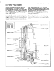
... our Customer Service Department toll-free at 1-800-999- Width: 38 in. The versatile PRO 9725 is WESY97250. Before reading further, please review the drawing below and familiarize yourself with the parts that are labeled. BEFORE YOU BEGIN Thank you want. 3756, Monday through Friday, 6 a.m. until 6 p.m. C Butterfly Arms 4 Squat Arm High Pulley Station Lat Bar Backrests Seats Weight Stack of 3 Press Arm Leg Lever Low Pulley Station...
... our Customer Service Department toll-free at 1-800-999- Width: 38 in. The versatile PRO 9725 is WESY97250. Before reading further, please review the drawing below and familiarize yourself with the parts that are labeled. BEFORE YOU BEGIN Thank you want. 3756, Monday through Friday, 6 a.m. until 6 p.m. C Butterfly Arms 4 Squat Arm High Pulley Station Lat Bar Backrests Seats Weight Stack of 3 Press Arm Leg Lever Low Pulley Station...
English Manual
Page 4
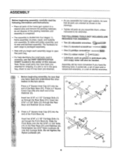
...: 1) frame assembly, 2) press, squat, and butterfly arm assembly, 3) cable and pulley assembly, and 4) seat and backrest assembly. Hand-tighten two 5/16" Nylon Locknuts (3) 11 4 onto the Carriage Bolts. ASSEMBLY Before beginning assembly, carefully read and understand the infor- 1 mation in the parts bag, check to see if it has been pre-attached. • As you assemble the home gym system, be more convenient if you assemble them, unless instructed to...
...: 1) frame assembly, 2) press, squat, and butterfly arm assembly, 3) cable and pulley assembly, and 4) seat and backrest assembly. Hand-tighten two 5/16" Nylon Locknuts (3) 11 4 onto the Carriage Bolts. ASSEMBLY Before beginning assembly, carefully read and understand the infor- 1 mation in the parts bag, check to see if it has been pre-attached. • As you assemble the home gym system, be more convenient if you assemble them, unless instructed to...
English Manual
Page 6
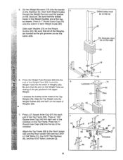
...). Insert both Weight Guides 5 through the Weight Bumpers and the bracket on the Stabilizer (5). Attach the Top Frame (55) to the Front Upright (42) and the Rear Upright (56) with four 5/16" x 2 3/4" Bolts (11), four 5/16" Flat Washers (8), and four 5/16" Nylon Locknuts (3). 6 7 11 27 8 55 44 3 56 3 11 27 49 44 27 Crossbar 42 Press a 1" Round Cover Cap (70...
...). Insert both Weight Guides 5 through the Weight Bumpers and the bracket on the Stabilizer (5). Attach the Top Frame (55) to the Front Upright (42) and the Rear Upright (56) with four 5/16" x 2 3/4" Bolts (11), four 5/16" Flat Washers (8), and four 5/16" Nylon Locknuts (3). 6 7 11 27 8 55 44 3 56 3 11 27 49 44 27 Crossbar 42 Press a 1" Round Cover Cap (70...

English Manual
Page 7
... the Front Base (4) with a 3/8" x 2 1/2" Bolt (7) and a 3/8" Nylon Locknut (21). Assemble the other Press Arm (46) in steps 2 through 8. 3\ 55 , 61 . 62 . 60 . . a 3 17 11 r7 A(.91-50 50.,--,tr_ i 6 -:- Lubricate the 3/8" x 8" Bolt (59). Note the position of the Press Frame (17) with the 5/16" x 6" Bolt (60), two 1/2" x 3/4" Spacers (61), and a 5/16" Nylon Locknut (3). Attach a "V"-Pulley (6) and a Long Cable Trap (50) to one...
... the Front Base (4) with a 3/8" x 2 1/2" Bolt (7) and a 3/8" Nylon Locknut (21). Assemble the other Press Arm (46) in steps 2 through 8. 3\ 55 , 61 . 62 . 60 . . a 3 17 11 r7 A(.91-50 50.,--,tr_ i 6 -:- Lubricate the 3/8" x 8" Bolt (59). Note the position of the Press Frame (17) with the 5/16" x 6" Bolt (60), two 1/2" x 3/4" Spacers (61), and a 5/16" Nylon Locknut (3). Attach a "V"-Pulley (6) and a Long Cable Trap (50) to one...
English Manual
Page 9
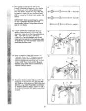
... this manual to hold the Cable in place. 15 55 23 21 0 . 5 Ball . Wrap the Medium Cable (23) around a 3 1/2" Pulley (15). Route the Medium Cable (23) around the "V"Pulley (6) on the Front Upright (42...Tighten the 3/8" x 2 1/2" Bolt (7) and the 3/8" Nylon Locknut (not shown). 6 7 5° 47 2 3 ill 9 Locate the Medium Cable (23). Attach the Pulley to turn freely. 14 C( ___( ) @.L.._( ) CJ--r S S-----L--®--86 (169") S 23 (155") S i===l-- 4--58 (47") 15. Be sure that 17 the Cable is in place. 14. During steps 15 through 36, refer to the CABLE DIAGRAM...
... this manual to hold the Cable in place. 15 55 23 21 0 . 5 Ball . Wrap the Medium Cable (23) around a 3 1/2" Pulley (15). Route the Medium Cable (23) around the "V"Pulley (6) on the Front Upright (42...Tighten the 3/8" x 2 1/2" Bolt (7) and the 3/8" Nylon Locknut (not shown). 6 7 5° 47 2 3 ill 9 Locate the Medium Cable (23). Attach the Pulley to turn freely. 14 C( ___( ) @.L.._( ) CJ--r S S-----L--®--86 (169") S 23 (155") S i===l-- 4--58 (47") 15. Be sure that 17 the Cable is in place. 14. During steps 15 through 36, refer to the CABLE DIAGRAM...

English Manual
Page 11
... the Medium Cable (23) around a 3 1/2" 21 Pulley (15). pletely tighten the Nylon Locknut. Attach the Pulley and a Cable Trap (66) to the Top Frame (55) with a 3/8" x 3 3/4" Bolt (71), a 3/8" Flat Washer (9), and a 3/8" Nylon Lock Nut (21). Ii I /`t lc) and a 1/4" Flat Washer (10). Locate the Short Cable (58). Wrap the Short Cable (58) around a 3 1/2" Pulley (15). Attach the Pulley to the Rear Upright (56) with a 3/8" x 1 3/4" Bolt (87) and...
... the Medium Cable (23) around a 3 1/2" 21 Pulley (15). pletely tighten the Nylon Locknut. Attach the Pulley and a Cable Trap (66) to the Top Frame (55) with a 3/8" x 3 3/4" Bolt (71), a 3/8" Flat Washer (9), and a 3/8" Nylon Lock Nut (21). Ii I /`t lc) and a 1/4" Flat Washer (10). Locate the Short Cable (58). Wrap the Short Cable (58) around a 3 1/2" Pulley (15). Attach the Pulley to the Rear Upright (56) with a 3/8" x 1 3/4" Bolt (87) and...

English Manual
Page 13
... that the Cable is routed around a "V"-Pulley (6). Attach the "V"-Pulley to the Press Frame (17) with a 3/8" x 3 3/4" Bolt (71), a 3/8" Flat Washer (9), and a 3/8" Nylon Locknut (21). Locate the Long Cable (86). Route the Long Cable under the 3 1/2" Low Pulley (88). Wrap the Long Cable (86) around a 3 1/2" Pulley (15). Wrap the Long Cable (86) around the Pulley as shown. 29. Be sure that the Cable is in the Front Upright (42...
... that the Cable is routed around a "V"-Pulley (6). Attach the "V"-Pulley to the Press Frame (17) with a 3/8" x 3 3/4" Bolt (71), a 3/8" Flat Washer (9), and a 3/8" Nylon Locknut (21). Locate the Long Cable (86). Route the Long Cable under the 3 1/2" Low Pulley (88). Wrap the Long Cable (86) around a 3 1/2" Pulley (15). Wrap the Long Cable (86) around the Pulley as shown. 29. Be sure that the Cable is in the Front Upright (42...

English Manual
Page 14
... Base (4) with a 3/8" x 3 1/2" Bolt (16), a 3/8" Flat Washer (9), and a 3/8" Nylon Locknut (21). Route the Long Cable (86) over the lower n 4 PV , II r- Attach the Pulley and a Cable 34 Trap (66) to hold the Cable in place and that the Cable Trap is routed around the Pulley as shown. r)..n.,..• I 81 15 86 42 9 21 H 34. The Cable must be routed from the CO' direction shown. Wrap...
... Base (4) with a 3/8" x 3 1/2" Bolt (16), a 3/8" Flat Washer (9), and a 3/8" Nylon Locknut (21). Route the Long Cable (86) over the lower n 4 PV , II r- Attach the Pulley and a Cable 34 Trap (66) to hold the Cable in place and that the Cable Trap is routed around the Pulley as shown. r)..n.,..• I 81 15 86 42 9 21 H 34. The Cable must be routed from the CO' direction shown. Wrap...

English Manual
Page 17
...) from the direction shown. Tighten a 5/16" Nylon Locknut (3) with a 1/4" Rat Washer (10) and the 1/4" x 2 1/4" Screw (82). 42. Insert the 1/4" x 2 1/4" Carriage Bolt (38) into the indicated hole in a Seat Plate (37). Press a 1 1/2" Square Inner Cap (32) into the center hole in the Front Seat Frame (36). The Leg Lever must be able to the Front Upright with the 5/16" x 2 1/4" Bolt and...
...) from the direction shown. Tighten a 5/16" Nylon Locknut (3) with a 1/4" Rat Washer (10) and the 1/4" x 2 1/4" Screw (82). 42. Insert the 1/4" x 2 1/4" Carriage Bolt (38) into the indicated hole in a Seat Plate (37). Press a 1 1/2" Square Inner Cap (32) into the center hole in the Front Seat Frame (36). The Leg Lever must be able to the Front Upright with the 5/16" x 2 1/4" Bolt and...

English Manual
Page 18
... over the pulleys. Make sure that the cables move smoothly, find and correct the problem. See the CABLE DIAGRAM on page 23 of this manual for proper cable routing. See TROUBLE-SHOOTING AND MAINTENANCE on page 19 of this manual.' EAT ASSEMB 44. Slide a Foam Pad (30) onto each cable a few times to the home gym system as 45 shown. If there is used. Insert the...
... over the pulleys. Make sure that the cables move smoothly, find and correct the problem. See the CABLE DIAGRAM on page 23 of this manual for proper cable routing. See TROUBLE-SHOOTING AND MAINTENANCE on page 19 of this manual.' EAT ASSEMB 44. Slide a Foam Pad (30) onto each cable a few times to the home gym system as 45 shown. If there is used. Insert the...
English Manual
Page 19
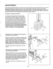
.... 25 26 ATTACHING THE LAT BAR OR NYLON STRAP TO THE HIGH PULLEY STATION Attach the Lat Bar (54) to be attached between the Lat Bar and the Medium Cable so the Lat Bar is in the same manner. CHANGING THE WEIGHT SETTING To change the weight setting of resistance at each part of 12.5 pounds. Refer to the exercise poster accompanying this manual to see how the home gym system should be performed. Adjust the length...
.... 25 26 ATTACHING THE LAT BAR OR NYLON STRAP TO THE HIGH PULLEY STATION Attach the Lat Bar (54) to be attached between the Lat Bar and the Medium Cable so the Lat Bar is in the same manner. CHANGING THE WEIGHT SETTING To change the weight setting of resistance at each part of 12.5 pounds. Refer to the exercise poster accompanying this manual to see how the home gym system should be performed. Adjust the length...
English Manual
Page 20
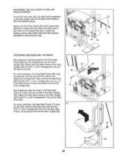
... Bolt (14) from the Eyebolt (35) before removing the seat. 53 0 52 35 29 86 ATTACHING AND REMOVING THE SEATS A See drawing A. Set the bracket on the Front Seat Frame (36) onto the indicated pins on the Front Upright (42). Lift the Front Seat Frame off the Rear Upright (56). 40 77 14-c, 56 20 ATTACHING THE LEG LEVER TO THE LOW PULLEY STATION To use the Leg...
... Bolt (14) from the Eyebolt (35) before removing the seat. 53 0 52 35 29 86 ATTACHING AND REMOVING THE SEATS A See drawing A. Set the bracket on the Front Seat Frame (36) onto the indicated pins on the Front Upright (42). Lift the Front Seat Frame off the Rear Upright (56). 40 77 14-c, 56 20 ATTACHING THE LEG LEVER TO THE LOW PULLEY STATION To use the Leg...

English Manual
Page 21
Weight resistance shown for the butterfly arm station is for each station. WEIGHT PLATES PRESS ARM (lbs.) BUTTERFLY ARM (lbs.) LEG LEVER (lbs.) HIGH PULLEY (lbs.) LOW PULLEY (lbs.) SQUAT ARM (lbs.) Top 24 1 45 2 69 3 98 4 117 5 142 6 ... resistance at each butterfly arm. top weight. The other numbers refer to differences in individual weight plates, as well as friction between the cables, pulleys, and weight guides. 21 weight plates. "Top" refers to the 6.5 lb. WEIGHT RESISTANCE CHART This chart shows the approximate weight resistance at each weight station...
Weight resistance shown for the butterfly arm station is for each station. WEIGHT PLATES PRESS ARM (lbs.) BUTTERFLY ARM (lbs.) LEG LEVER (lbs.) HIGH PULLEY (lbs.) LOW PULLEY (lbs.) SQUAT ARM (lbs.) Top 24 1 45 2 69 3 98 4 117 5 142 6 ... resistance at each butterfly arm. top weight. The other numbers refer to differences in individual weight plates, as well as friction between the cables, pulleys, and weight guides. 21 weight plates. "Top" refers to the 6.5 lb. WEIGHT RESISTANCE CHART This chart shows the approximate weight resistance at each weight station...
English Manual
Page 22
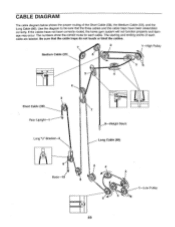
... cable are labeled. CABLE DIAGRAM The cable diagram below shows the proper routing of each cable. Be sure that the three cables and the cable traps have not been correctly routed, the home gym system will not function properly and damage may occur. Use the diagram to be sure that the cable traps do not touch or bind the cables. 7 2 1-High Pulley Medium Cable (23) 8 14) Short Cable (58) Rear Upright-1 6 2 0 5 7 4 O Weight...
... cable are labeled. CABLE DIAGRAM The cable diagram below shows the proper routing of each cable. Be sure that the three cables and the cable traps have not been correctly routed, the home gym system will not function properly and damage may occur. Use the diagram to be sure that the cable traps do not touch or bind the cables. 7 2 1-High Pulley Medium Cable (23) 8 14) Short Cable (58) Rear Upright-1 6 2 0 5 7 4 O Weight...
English Manual
Page 23
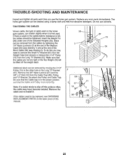
... Weight Pin (26) under one of the Short Cable (58) (see ORDERING 86 REPLACEMENT PARTS on the home gym system, can be replaced, see drawing 2). Remove the 15 cable and re-install it is felt, the cables should be cleaned using a damp cloth and mild non-abrasive detergent. TROUBLE-SHOOTING AND MAINTENANCE Inspect and tighten all parts each time you may have become twisted. Replace any worn parts immediately. TIGHTENING...
... Weight Pin (26) under one of the Short Cable (58) (see ORDERING 86 REPLACEMENT PARTS on the home gym system, can be replaced, see drawing 2). Remove the 15 cable and re-install it is felt, the cables should be cleaned using a damp cloth and mild non-abrasive detergent. TROUBLE-SHOOTING AND MAINTENANCE Inspect and tighten all parts each time you may have become twisted. Replace any worn parts immediately. TIGHTENING...

English Manual
Page 24
... of purchase. ORDERING REPLACEMENT PARTS To order replacement parts, simply call our Customer Service Department toll-free at the center of this manual). Mountain Time (excluding holidays). All returns must be prepared to replacing or repairing, at ICON's option, the product at one of its authorized service centers. ICON's obligation under normal use , costs of removal, installation or other warranty beyond that specifically set forth herein. ICON HEALTH & FITNESS, INC., 1500...
... of purchase. ORDERING REPLACEMENT PARTS To order replacement parts, simply call our Customer Service Department toll-free at the center of this manual). Mountain Time (excluding holidays). All returns must be prepared to replacing or repairing, at ICON's option, the product at one of its authorized service centers. ICON's obligation under normal use , costs of removal, installation or other warranty beyond that specifically set forth herein. ICON HEALTH & FITNESS, INC., 1500...
English Manual
Page 25
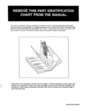
... divided into four stages: 1) frame assembly, 2) press, squat, and butterfly arm assembly, 3) cable and pulley assembly, and 4) seat and backrest assembly. WESY97250 R0897A The number in parenthesis below each part refers to open that parts bag. Wait until you begin each stage is packaged separately. Important: Some parts may have been pre-assembled for each assembly stage to the key number of the part. The hardware for shipping purposes...
... divided into four stages: 1) frame assembly, 2) press, squat, and butterfly arm assembly, 3) cable and pulley assembly, and 4) seat and backrest assembly. WESY97250 R0897A The number in parenthesis below each part refers to open that parts bag. Wait until you begin each stage is packaged separately. Important: Some parts may have been pre-assembled for each assembly stage to the key number of the part. The hardware for shipping purposes...
English Manual
Page 31
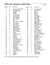
...Clip Lat Bar Top Frame Rear Upright Long "U"-Bracket Short Cable 3/8" x 8" Bolt 5/16" x 6" Bolt 1/2" x 3/4" Spacer Weight Guide Weight Tube Weight Tube Bumper 1" Square Inner Cap Cable Trap Small "U"-Bracket 5/16" x 5" Bolt 1" Retainer 1" Round Cover Cap 3/8" x 3 3/4" Bolt 5/16" x 1 3/4" Bolt 5/8" x 9/16" Spacer 4 4 ill" I " Plate 1/4" x 2 1/4" Screw 1" x 2" Inner Cap 5/16" Nylon Jam Nut 3/8" x 3 1/4" Bolt Long Cable 3/8" x 1 3/4" Bolt 3 1/2" Low Pulley #8 x 1/2" Tap Screw Rubber Bumper 1/4" x 2 1/2" Carriage Bolt Handle 5/16" x 3" Bolt User's Manual Exercise...
...Clip Lat Bar Top Frame Rear Upright Long "U"-Bracket Short Cable 3/8" x 8" Bolt 5/16" x 6" Bolt 1/2" x 3/4" Spacer Weight Guide Weight Tube Weight Tube Bumper 1" Square Inner Cap Cable Trap Small "U"-Bracket 5/16" x 5" Bolt 1" Retainer 1" Round Cover Cap 3/8" x 3 3/4" Bolt 5/16" x 1 3/4" Bolt 5/8" x 9/16" Spacer 4 4 ill" I " Plate 1/4" x 2 1/4" Screw 1" x 2" Inner Cap 5/16" Nylon Jam Nut 3/8" x 3 1/4" Bolt Long Cable 3/8" x 1 3/4" Bolt 3 1/2" Low Pulley #8 x 1/2" Tap Screw Rubber Bumper 1/4" x 2 1/2" Carriage Bolt Handle 5/16" x 3" Bolt User's Manual Exercise...


