

English Manual
Page 2
... pre-existing health problems. Read all instructions before beginning assembly. Table of Contents IMPORTANT PRECAUTIONS 2 BEFORE YOU BEGIN 3 ASSEMBLY 4 HOW TO USE THE HOME GYM SYSTEM 22 WEIGHT RESISTANCE CHART 24 TROUBLE-SHOOTING AND MAINTENANCE 25 CABLE DIAGRAMS 26 ORDERING REPLACEMENT PARTS Back Cover LIMITED WARRANTY Back Cover Note: A PART IDENTIFICATION CHART and a PART LIST/EXPLODED DRAWING are on all of the pulleys. 12. Remove the PART IDENTIFICATION CHART and the PART LIST/EXPLODED DRAWING before using the home gym system. 3. Use the home gym system only...
... pre-existing health problems. Read all instructions before beginning assembly. Table of Contents IMPORTANT PRECAUTIONS 2 BEFORE YOU BEGIN 3 ASSEMBLY 4 HOW TO USE THE HOME GYM SYSTEM 22 WEIGHT RESISTANCE CHART 24 TROUBLE-SHOOTING AND MAINTENANCE 25 CABLE DIAGRAMS 26 ORDERING REPLACEMENT PARTS Back Cover LIMITED WARRANTY Back Cover Note: A PART IDENTIFICATION CHART and a PART LIST/EXPLODED DRAWING are on all of the pulleys. 12. Remove the PART IDENTIFICATION CHART and the PART LIST/EXPLODED DRAWING before using the home gym system. 3. Use the home gym system only...

English Manual
Page 3
... Backrest Press Arm Leg Lever Low Pulley Station Leg Press Plate Foot Plate Weight Stacks 3 Before You Begin Thank you , please note the product model number and serial number before using the WEIDER¨ PRO 9925 Training System. Customer Service Department toll-free at 1-800-999-3756, Monday through Friday, 6 a.m. To help you to the WEIDER¨ PRO 9925 (see the front cover of the body. Mountain Time, to the location shown. until 6 p.m. The model number...
... Backrest Press Arm Leg Lever Low Pulley Station Leg Press Plate Foot Plate Weight Stacks 3 Before You Begin Thank you , please note the product model number and serial number before using the WEIDER¨ PRO 9925 Training System. Customer Service Department toll-free at 1-800-999-3756, Monday through Friday, 6 a.m. To help you to the WEIDER¨ PRO 9925 (see the front cover of the body. Mountain Time, to the location shown. until 6 p.m. The model number...

English Manual
Page 4
... (2) adjustable wrenches ¥ One (1) standard screwdriver Unpacking the Box To make the task enjoyable, assembly will be sure that connect the moving parts will begin the assembly process itself, take timeÑpossibly several hours. Some assembly steps require two people. The seat and all moving arms with many small parts. Cable Assembly Completes the cables and pulleys that all parts as the skeleton of open the parts bag...
... (2) adjustable wrenches ¥ One (1) standard screwdriver Unpacking the Box To make the task enjoyable, assembly will be sure that connect the moving parts will begin the assembly process itself, take timeÑpossibly several hours. Some assembly steps require two people. The seat and all moving arms with many small parts. Cable Assembly Completes the cables and pulleys that all parts as the skeleton of open the parts bag...
English Manual
Page 6
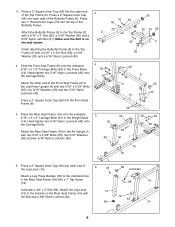
... side shown. Hand tighten two 5/16Ó Nylon Locknuts (40) onto the Carriage Bolts. 4 55 20 Attach the other end of the Front Seat Frame (8) to the Ab Upright (1) with two 5/16Ó x 2 3/4Ó Bolts (55), two 5/16Ó Washers (20) and two 5/16Ó Nylon Locknuts (40). Attach the Rear Seat Frame (16) to the Leg Press Upright (4) with two 5/16...
... side shown. Hand tighten two 5/16Ó Nylon Locknuts (40) onto the Carriage Bolts. 4 55 20 Attach the other end of the Front Seat Frame (8) to the Ab Upright (1) with two 5/16Ó x 2 3/4Ó Bolts (55), two 5/16Ó Washers (20) and two 5/16Ó Nylon Locknuts (40). Attach the Rear Seat Frame (16) to the Leg Press Upright (4) with two 5/16...
English Manual
Page 9
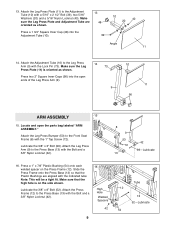
... Lock Pin (73). Attach the Leg Press Plate (11) to the Front Seat Frame (8) with a 5/16Ó x 2 1/2Ó Bolt (39), two 5/16Ó Washers (20) and a 5/16Ó Nylon Locknut (40). Make sure the Leg Press Plate (11) is on the Press Frame (12). Locate and open ends of the Leg Press Arm (9). 14 73 9 10 11 56 ARM ASSEMBLY 15 15. Attach the Leg Press Arm (9) to the Press Base...
... Lock Pin (73). Attach the Leg Press Plate (11) to the Front Seat Frame (8) with a 5/16Ó x 2 1/2Ó Bolt (39), two 5/16Ó Washers (20) and a 5/16Ó Nylon Locknut (40). Make sure the Leg Press Plate (11) is on the Press Frame (12). Locate and open ends of the Leg Press Arm (9). 14 73 9 10 11 56 ARM ASSEMBLY 15 15. Attach the Leg Press Arm (9) to the Press Base...
English Manual
Page 10
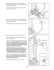
...they must be assembled only once. Attach the Right Arm (5) in the same manner. 39 7 18. Attach the other Press Arm (not shown). 40 7 12 48 80 7 19. Lubricate both axles on the Butterfly Frame (3). 19 Refer to one Press Arm (7). Be sure that you will need to order new Retainers. Press a 1 ... Outer Cap, as shown in this step for the other Press Arm (7) to confuse the Left Arm with two 5/16Ó x 2 1/2Ó Bolts (39) and two 5/16Ó Nylon Locknuts (40). The Retainers can be removed, you thoroughly understand the step. Press a 1Ó Inner Cap (80)...
...they must be assembled only once. Attach the Right Arm (5) in the same manner. 39 7 18. Attach the other Press Arm (not shown). 40 7 12 48 80 7 19. Lubricate both axles on the Butterfly Frame (3). 19 Refer to one Press Arm (7). Be sure that you will need to order new Retainers. Press a 1 ... Outer Cap, as shown in this step for the other Press Arm (7) to confuse the Left Arm with two 5/16Ó x 2 1/2Ó Bolts (39) and two 5/16Ó Nylon Locknuts (40). The Retainers can be removed, you thoroughly understand the step. Press a 1Ó Inner Cap (80)...
English Manual
Page 11
Locate and open the parts bags labeled ÒCABLE ASSEMBLYÓ and ÒPULLEYS.Ó During steps 19 through the bracket on pages 26 and 27 of each Cable, in the drawing. Tighten a 5/16Ó Nylon Jam Nut (91) onto the Bolt. The approximate length of this manual to the CABLE DIAGRAMS on 22 the Right Arm (5). Slide one end of the Left Arm (6) and the...
Locate and open the parts bags labeled ÒCABLE ASSEMBLYÓ and ÒPULLEYS.Ó During steps 19 through the bracket on pages 26 and 27 of each Cable, in the drawing. Tighten a 5/16Ó Nylon Jam Nut (91) onto the Bolt. The approximate length of this manual to the CABLE DIAGRAMS on 22 the Right Arm (5). Slide one end of the Left Arm (6) and the...
English Manual
Page 12
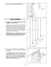
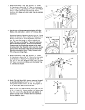
...). Locate one of the preassembled pairs of the Butterfly Cable (89) onto the 5/16Ó x 1Ó Bolt (97). Note: The Left Arm (6) is over the stresspoint, where the Cable wraps around a 3 1/2Ó Pulley (82) in the following assembly steps. Use this orientation of the bracket on the Left Arm. Wide Tab Stress-point on the Leg Press Upright (4) with a 3/8Ó x 2 1/2Ó Bolt (65), a Large Cable...
...). Locate one of the preassembled pairs of the Butterfly Cable (89) onto the 5/16Ó x 1Ó Bolt (97). Note: The Left Arm (6) is over the stresspoint, where the Cable wraps around a 3 1/2Ó Pulley (82) in the following assembly steps. Use this orientation of the bracket on the Left Arm. Wide Tab Stress-point on the Leg Press Upright (4) with a 3/8Ó x 2 1/2Ó Bolt (65), a Large Cable...
English Manual
Page 13
...) until the Weight Spacer (32) touches the Weight Tube. Orient the wide tab on top of the Rear 30 Cable (87). Attach the Pulley to pivot. 91 92 87 28. Thread the end of the Rear Cable (87) into the upper end of the Rear Cable onto the 5/16Ó x 3Ó Bolt (92). The Cable must be routed from the direction shown. 82 94...
...) until the Weight Spacer (32) touches the Weight Tube. Orient the wide tab on top of the Rear 30 Cable (87). Attach the Pulley to pivot. 91 92 87 28. Thread the end of the Rear Cable (87) into the upper end of the Rear Cable onto the 5/16Ó x 3Ó Bolt (92). The Cable must be routed from the direction shown. 82 94...
English Manual
Page 17
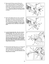
... (43). Attach the Pulley and two Pulley Covers (94) to pivot. 8 20 55 88 91 44. Insert the Bolt into the Front Seat Frame (8). Make sure the end of the Press Cable (88) onto the Bolt. Wrap the Press Cable (88) around a 3 1/2Ó Pulley (82) in step 40. Leave enough room between the Pulley and the post. Attach the Pulley and two Pulley Covers (94) to the Leg Press Arm (9) with...
... (43). Attach the Pulley and two Pulley Covers (94) to pivot. 8 20 55 88 91 44. Insert the Bolt into the Front Seat Frame (8). Make sure the end of the Press Cable (88) onto the Bolt. Wrap the Press Cable (88) around a 3 1/2Ó Pulley (82) in step 40. Leave enough room between the Pulley and the post. Attach the Pulley and two Pulley Covers (94) to the Leg Press Arm (9) with...
English Manual
Page 18
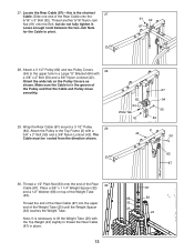
... (25) with the Top Weight (24) slightly to the Pulley Plates (31) with a 3/8Ó x 3 3/4Ó Bolt (76), two 3/8Ó Washers (38) and a 3/8Ó Nylon Jam Nut (43). Route the High Cable (85) around a 3 1/2Ó Pulley (82) 47 in the direction shown. Wrap the High Cable (85) around a 3 1/2Ó Pulley (82) in the direction shown. Attach the Pulley and two Pulley Covers (94) to thread...
... (25) with the Top Weight (24) slightly to the Pulley Plates (31) with a 3/8Ó x 3 3/4Ó Bolt (76), two 3/8Ó Washers (38) and a 3/8Ó Nylon Jam Nut (43). Route the High Cable (85) around a 3 1/2Ó Pulley (82) 47 in the direction shown. Wrap the High Cable (85) around a 3 1/2Ó Pulley (82) in the direction shown. Attach the Pulley and two Pulley Covers (94) to thread...
English Manual
Page 20
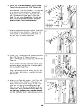
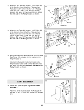
... (43). Locate and open the parts bag labeled ÒSEAT ASSEMBLY.Ó Attach the Small Backrest (18) to the indicated hole in the direction shown. 53. Wrap the Low Cable (86) around a 3 1/2Ó Pulley (82) 54 in the Ab Upright (1) with a 3/8Ó x 1 1/2Ó Bolt (66) and a 3/8Ó Nylon Jam Nut (43). Attach a Pro Pulley (62) inside the bracket on the Pulley Covers as shown. 86 SEAT ASSEMBLY 56...
... (43). Locate and open the parts bag labeled ÒSEAT ASSEMBLY.Ó Attach the Small Backrest (18) to the indicated hole in the direction shown. 53. Wrap the Low Cable (86) around a 3 1/2Ó Pulley (82) 54 in the Ab Upright (1) with a 3/8Ó x 1 1/2Ó Bolt (66) and a 3/8Ó Nylon Jam Nut (43). Attach a Pro Pulley (62) inside the bracket on the Pulley Covers as shown. 86 SEAT ASSEMBLY 56...

English Manual
Page 22
... need to remove the slack by tightening the cables. IMPORTANT: If the cables are not properly installed, they may be sure that all parts have been properly tightened. See TROUBLE-SHOOTING AND MAINTENANCE on page 23 of this step for proper cable routing. See the CABLE DIAGRAMS on page 26 and 27 of this manual. If one of the Uprights, as shown. 59 59 59 51 64. Attach...
... need to remove the slack by tightening the cables. IMPORTANT: If the cables are not properly installed, they may be sure that all parts have been properly tightened. See TROUBLE-SHOOTING AND MAINTENANCE on page 23 of this step for proper cable routing. See the CABLE DIAGRAMS on page 26 and 27 of this manual. If one of the Uprights, as shown. 59 59 59 51 64. Attach...

English Manual
Page 23
... of resistance at each weight station. 90 93 ATTACHING THE LAT BAR OR NYLON STRAP TO THE LOW PULLEY STATION 33 Attach the Lat Bar (36) to the fly and press arms and the leg press. 93 To change the weight setting of either weight stack can be attached in the same man- 96 ner. Note: Due to Use the Home Gym System The instructions below describe how each part of either weight stack, insert a Weight Pin...
... of resistance at each weight station. 90 93 ATTACHING THE LAT BAR OR NYLON STRAP TO THE LOW PULLEY STATION 33 Attach the Lat Bar (36) to the fly and press arms and the leg press. 93 To change the weight setting of either weight stack can be attached in the same man- 96 ner. Note: Due to Use the Home Gym System The instructions below describe how each part of either weight stack, insert a Weight Pin...

English Manual
Page 24
...) should be performed. ATTACHING THE AB STRAP TO THE AB PULLEY STATION Attach the Ab Strap (35) to be attached between the Lat Bar and the High Cable so the Lat Bar is in the same manner. ADJUSTING THE FOAM PADS The Foam Pads (29) attached to the Leg Lever (15) can be attached in the correct starting position for the exercise to the Low Cable (86) at...
...) should be performed. ATTACHING THE AB STRAP TO THE AB PULLEY STATION Attach the Ab Strap (35) to be attached between the Lat Bar and the High Cable so the Lat Bar is in the same manner. ADJUSTING THE FOAM PADS The Foam Pads (29) attached to the Leg Lever (15) can be attached in the correct starting position for the exercise to the Low Cable (86) at...

English Manual
Page 25
... (32) can be removed. Remove the cable and re-install it. 86, 88 If the cables need to be tightened. To tighten the cables, first insert the weight pin into the spider nut (not shown) in the end of cable used . Re-attach the Pulley and Pulley Covers to the other weight stack, the Rear Cable (87), the Press Cable (88), and the Butterfly Cable (89) will need to slip off the weight stack. 3 82 50...
... (32) can be removed. Remove the cable and re-install it. 86, 88 If the cables need to be tightened. To tighten the cables, first insert the weight pin into the spider nut (not shown) in the end of cable used . Re-attach the Pulley and Pulley Covers to the other weight stack, the Rear Cable (87), the Press Cable (88), and the Butterfly Cable (89) will need to slip off the weight stack. 3 82 50...
English Manual
Page 26
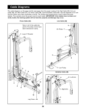
... all of the cable diagrams, the pulley covers have been assembled correctly. The starting and ending points of the High Cable (85), the Low Cable (86), the Rear Cable (87), the Press Cable (88), and the Butterfly Cable (89). Use the diagrams to be sure that the Cables have been removed for each Cable have been labeled. IMPORTANT: If the Cables have not been correctly routed, the training system will not...
... all of the cable diagrams, the pulley covers have been assembled correctly. The starting and ending points of the High Cable (85), the Low Cable (86), the Rear Cable (87), the Press Cable (88), and the Butterfly Cable (89). Use the diagrams to be sure that the Cables have been removed for each Cable have been labeled. IMPORTANT: If the Cables have not been correctly routed, the training system will not...
English Manual
Page 27
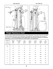
... Cable (85) High PulleyÑ1 2 4 Rear Cable (87) 1ÑTop Frame 3 2 3 4ÑWeight Stack Weight StackÑ5 Weight Resistance Chart This chart shows the approximate weight resistance at each weight station may vary due to differences in individual weight plates, as well as friction between the cables, pulleys, and weight guides. The actual resistance at each butterfly arm. WEIGHT PLATES PRESS ARM (lbs.) BUTTERFLY ARM (lbs.) LEG LEVER (lbs.) HIGH PULLEY (lbs.) LOW PULLEY (lbs.) LEG PRESS (lbs.) AB PULLEY...
... Cable (85) High PulleyÑ1 2 4 Rear Cable (87) 1ÑTop Frame 3 2 3 4ÑWeight Stack Weight StackÑ5 Weight Resistance Chart This chart shows the approximate weight resistance at each weight station may vary due to differences in individual weight plates, as well as friction between the cables, pulleys, and weight guides. The actual resistance at each butterfly arm. WEIGHT PLATES PRESS ARM (lbs.) BUTTERFLY ARM (lbs.) LEG LEVER (lbs.) HIGH PULLEY (lbs.) LOW PULLEY (lbs.) LEG PRESS (lbs.) AB PULLEY...

English Manual
Page 31
... 9 Description Ab Upright Top Frame Butterfly Frame Leg Press Upright Right Fly Arm Left Fly Arm Press Arm Front Seat Frame Leg Press Arm Adjustment Tube Leg Press Plate Press Frame Press Base Weight Base Leg Lever Rear Seat Frame Seat Small Backrest Large Backrest 5/16Ó Washer 5Ó Plastic Grip Butterfly Pad Weight Guide Top Weight Weight Tube Weight Tube Bumper Weight Bumper Pad Tube Foam Pad Leg Lever Spacer Pulley Plate 3/8Ó x 1 1/4Ó Weight Spacer Cable Clip Chain Ab Strap Lat Bar 1/4Ó...
... 9 Description Ab Upright Top Frame Butterfly Frame Leg Press Upright Right Fly Arm Left Fly Arm Press Arm Front Seat Frame Leg Press Arm Adjustment Tube Leg Press Plate Press Frame Press Base Weight Base Leg Lever Rear Seat Frame Seat Small Backrest Large Backrest 5/16Ó Washer 5Ó Plastic Grip Butterfly Pad Weight Guide Top Weight Weight Tube Weight Tube Bumper Weight Bumper Pad Tube Foam Pad Leg Lever Spacer Pulley Plate 3/8Ó x 1 1/4Ó Weight Spacer Cable Clip Chain Ab Strap Lat Bar 1/4Ó...
English Manual
Page 33
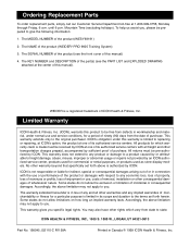
... © 1999 ICON Health & Fitness, Inc. No other rights which warranty claim is limited to replacing or repairing, at ICON's option, the product at one of the product (see the PART LIST and EXPLODED DRAWING attached at 1-800-999-3756, Monday through Friday, 6 a.m. The SERIAL NUMBER of its authorized service centers. This warranty gives you . You may also have other warranty beyond that specifically set forth herein. Mountain...
... © 1999 ICON Health & Fitness, Inc. No other rights which warranty claim is limited to replacing or repairing, at ICON's option, the product at one of the product (see the PART LIST and EXPLODED DRAWING attached at 1-800-999-3756, Monday through Friday, 6 a.m. The SERIAL NUMBER of its authorized service centers. This warranty gives you . You may also have other warranty beyond that specifically set forth herein. Mountain...


