

English Manual
Page 1
As a manufacturer, we are missing or damaged parts, we will provide immediate assistance, free of charge to providing complete customer satisfaction. The trained technicians on our customer hot line will guarantee complete satisfaction through direct assistance from our factory. Save this equipment. If you have questions, or if there are committed to you. TO AVOID UNNECESSARY DELAYS, PLEASE CALL DIRECT TO OUR TOLL-FREE CUSTOMER HOT LINE. MST Patent Pending CAUTION Read all precautions and instructions in the space above for future reference. Serial Number Decal (Under ...
As a manufacturer, we are missing or damaged parts, we will provide immediate assistance, free of charge to providing complete customer satisfaction. The trained technicians on our customer hot line will guarantee complete satisfaction through direct assistance from our factory. Save this equipment. If you have questions, or if there are committed to you. TO AVOID UNNECESSARY DELAYS, PLEASE CALL DIRECT TO OUR TOLL-FREE CUSTOMER HOT LINE. MST Patent Pending CAUTION Read all precautions and instructions in the space above for future reference. Serial Number Decal (Under ...

English Manual
Page 2
Remove the PART IDENTIFICATION CHART and the PART LIST/EXPLODED DRAWING before using . Important Precautions WARNING: To reduce the risk of serious injury, read the following important precautions before beginning assembly. Always stand on all of the pulleys. 12. Replace any exercise program, consult your physician. Keep children under the age of 12 and pets away from the home gym system at any commercial, rental or institutional setting. Keep hands and feet away from the home gym system when performing an exercise that does not use the home gym system in the accompanying ...
Remove the PART IDENTIFICATION CHART and the PART LIST/EXPLODED DRAWING before using . Important Precautions WARNING: To reduce the risk of serious injury, read the following important precautions before beginning assembly. Always stand on all of the pulleys. 12. Replace any exercise program, consult your physician. Keep children under the age of 12 and pets away from the home gym system at any commercial, rental or institutional setting. Keep hands and feet away from the home gym system when performing an exercise that does not use the home gym system in the accompanying ...

English Manual
Page 3
...additional questions, please call our Customer Service Department toll-free at 1-800-9993756, Monday through Friday, 6 a.m. For your cardiovascular system, the WEIDER¨ PRO 9925 will help us assist you want. Length: 70 in . until 6 p.m. The decal shown to order a replacement decal. until 6 p.m.... decal to achieve the specific results you , please note the product model number and serial number before using the WEIDER¨ PRO 9925 Training System. Width: 64 in the two locations shown. Warning Decal Ab Pulley Station Backrest Curl Pad Butterfly Arms...
...additional questions, please call our Customer Service Department toll-free at 1-800-9993756, Monday through Friday, 6 a.m. For your cardiovascular system, the WEIDER¨ PRO 9925 will help us assist you want. Length: 70 in . until 6 p.m. The decal shown to order a replacement decal. until 6 p.m.... decal to achieve the specific results you , please note the product model number and serial number before using the WEIDER¨ PRO 9925 Training System. Width: 64 in the two locations shown. Warning Decal Ab Pulley Station Backrest Curl Pad Butterfly Arms...

English Manual
Page 4
Clearing the Workspace Clear a workspace that all the way around the assembled equipment. If a part is not in each other and with many small parts. Cable Assembly Completes the cables and pulleys that connect the moving parts will save you more convenient if you identify the small parts used in the parts bag, check to see if it is a sophisticated product with the weights. Arm Assembly Completes the press and butterfly arms that assembly stage. Place the chart on the floor or work table and use it to quickly identify different parts as you open the packages for ...
Clearing the Workspace Clear a workspace that all the way around the assembled equipment. If a part is not in each other and with many small parts. Cable Assembly Completes the cables and pulleys that connect the moving parts will save you more convenient if you identify the small parts used in the parts bag, check to see if it is a sophisticated product with the weights. Arm Assembly Completes the press and butterfly arms that assembly stage. Place the chart on the floor or work table and use it to quickly identify different parts as you open the packages for ...
English Manual
Page 5
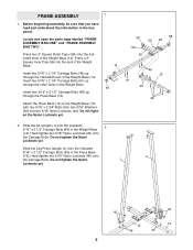
Press a 2Ó Square Inner Cap (56) into the end of the Weight Base (14). Attach the Press Base (13) to the Weight Base (14) with two 5/16Ó x 2 3/4Ó Bolts (55), two 5/16Ó Washers (20) and two 5/16Ó Nylon Locknuts (40). Slide the Leg Press Upright (4) onto the indicated 5/16Ó x 2 1/2Ó Carriage Bolts (49) in the box above. Before beginning assembly, be sure that you have read and understand the information in the Press Base (13). cated ends of the Weight Base. 14 Insert two 5/16Ó x 2 1/2Ó Carriage Bolts (49) up through ...
Press a 2Ó Square Inner Cap (56) into the end of the Weight Base (14). Attach the Press Base (13) to the Weight Base (14) with two 5/16Ó x 2 3/4Ó Bolts (55), two 5/16Ó Washers (20) and two 5/16Ó Nylon Locknuts (40). Slide the Leg Press Upright (4) onto the indicated 5/16Ó x 2 1/2Ó Carriage Bolts (49) in the box above. Before beginning assembly, be sure that you have read and understand the information in the Press Base (13). cated ends of the Weight Base. 14 Insert two 5/16Ó x 2 1/2Ó Carriage Bolts (49) up through ...
English Manual
Page 6
Slide the Front Seat Frame (8) onto the indicated 5/16Ó x 2 1/2Ó Carriage Bolts (49) in the Rear Seat Frame (16) with two 5/16Ó x 2 3/4Ó Bolts (55), two 5/16Ó Washers (20) and two 5/16Ó Nylon Locknuts (40). 16 40 40 4 13 49 55 55 40 1 8 56 40 20 40 20 14 61 6. Press a 2Ó Square Inner Cap (56) into the top of the Butterfly Frame. Press a 2Ó Square Inner Cap (56) into each side of the Top Frame (2). Attach the Leg Lever 15 (15) to the indicated hole in the Press Base (13). Press two 1Ó Round Inner Caps (70) into the Front ...
Slide the Front Seat Frame (8) onto the indicated 5/16Ó x 2 1/2Ó Carriage Bolts (49) in the Rear Seat Frame (16) with two 5/16Ó x 2 3/4Ó Bolts (55), two 5/16Ó Washers (20) and two 5/16Ó Nylon Locknuts (40). 16 40 40 4 13 49 55 55 40 1 8 56 40 20 40 20 14 61 6. Press a 2Ó Square Inner Cap (56) into the top of the Butterfly Frame. Press a 2Ó Square Inner Cap (56) into each side of the Top Frame (2). Attach the Leg Lever 15 (15) to the indicated hole in the Press Base (13). Press two 1Ó Round Inner Caps (70) into the Front ...

English Manual
Page 7
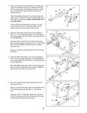
7. Attach the lower ends of Weights. 14 69 67 90 Pin Grooves 90 Pin 27 Grooves 27 23 23 9. Do not overtighten the Nylon Locknut. Attach the other Weight Guides (23) in the upper Weights. 25 26 90 90 Pin Grooves 7 Make sure the pins on the Weight Base (14). Make sure the pin grooves are in the pin grooves in the same manner. 23 23 40 8. Press a Weight Tube Bumper (26) into each stack of the Weight Guides with a 5/16Ó x 6Ó Bolt (67), two 1/2Ó x 3/4Ó Spacers (69), and a 5/16Ó Nylon Locknut (40). Insert two Weight Guides (23) ...
7. Attach the lower ends of Weights. 14 69 67 90 Pin Grooves 90 Pin 27 Grooves 27 23 23 9. Do not overtighten the Nylon Locknut. Attach the other Weight Guides (23) in the upper Weights. 25 26 90 90 Pin Grooves 7 Make sure the pins on the Weight Base (14). Make sure the pin grooves are in the pin grooves in the same manner. 23 23 40 8. Press a Weight Tube Bumper (26) into each stack of the Weight Guides with a 5/16Ó x 6Ó Bolt (67), two 1/2Ó x 3/4Ó Spacers (69), and a 5/16Ó Nylon Locknut (40). Insert two Weight Guides (23) ...

English Manual
Page 8
10. Attach the Top Frame (2) to the Ab Upright (1) with two 5/16Ó x 2 3/4Ó Bolts (55), a 20 3 Support Plate (95) and two 5/16Ó Nylon Locknuts 2 (40). Attach the upper ends of the other set of Weight Guides (23) to the Leg Press Upright (4) with 11 two 5/16Ó x 2 3/4Ó Bolts (55), two 5/16Ó Washers (20) and two 5/16Ó Nylon Locknuts (40). Do not tighten the Nylon Locknuts yet. 55 95 55 Attach the Butterfly Frame (3) to the Top Frame (2) with a 5/16Ó x 6Ó Bolt (67), two 1/2Ó x 3/4Ó Spacers (69) and a 5/16Ó ...
10. Attach the Top Frame (2) to the Ab Upright (1) with two 5/16Ó x 2 3/4Ó Bolts (55), a 20 3 Support Plate (95) and two 5/16Ó Nylon Locknuts 2 (40). Attach the upper ends of the other set of Weight Guides (23) to the Leg Press Upright (4) with 11 two 5/16Ó x 2 3/4Ó Bolts (55), two 5/16Ó Washers (20) and two 5/16Ó Nylon Locknuts (40). Do not tighten the Nylon Locknuts yet. 55 95 55 Attach the Butterfly Frame (3) to the Top Frame (2) with a 5/16Ó x 6Ó Bolt (67), two 1/2Ó x 3/4Ó Spacers (69) and a 5/16Ó ...
English Manual
Page 9
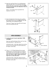
13. Make sure the Leg Press Plate (11) is on the Press Frame (12). Press two 2Ó Square Inner Caps (56) into the Adjustment Tube (10). 39 10 20 40 Angle 11 14. Slide the Press Frame onto the Press Base (13) so that the high hole is oriented as shown. 13 48 Press a 1 3/4Ó Square Inner Cap (48) into the open the parts bag labeled ÒARM ASSEMBLY.Ó Attach the Leg Press Bumper (53) to the Press Base (13) with the Bolt and a 3/8Ó Nylon Locknut (42). 16 High Hole Welded Spacers 42 9 Tube 12 13 52ÑLubricate 54 Locate and open ends of the Leg ...
13. Make sure the Leg Press Plate (11) is on the Press Frame (12). Press two 2Ó Square Inner Caps (56) into the Adjustment Tube (10). 39 10 20 40 Angle 11 14. Slide the Press Frame onto the Press Base (13) so that the high hole is oriented as shown. 13 48 Press a 1 3/4Ó Square Inner Cap (48) into the open the parts bag labeled ÒARM ASSEMBLY.Ó Attach the Leg Press Bumper (53) to the Press Base (13) with the Bolt and a 3/8Ó Nylon Locknut (42). 16 High Hole Welded Spacers 42 9 Tube 12 13 52ÑLubricate 54 Locate and open ends of the Leg ...
English Manual
Page 10
Slide the Left Arm onto the indicated axle. Be sure that the teeth on the Retainers bend toward the Round Outer Cap, as shown in this step for the other Press Arm (7) to the Press Frame (12) in the same manner. 3 Lubricate Axle 48 Bracket 45 46 6 Axle 45 46 10 Press a 1 3/4Ó Square Inner Cap (48) into the indicated end of 18 one side of the Left Arm (6). Press a 1 3/4Ó Square Inner Cap (48) into the upper end of the Press 17 Frame (12) with the Right Arm (5). Note: Be careful not to order new Retainers. The Retainers can be sure that ...
Slide the Left Arm onto the indicated axle. Be sure that the teeth on the Retainers bend toward the Round Outer Cap, as shown in this step for the other Press Arm (7) to the Press Frame (12) in the same manner. 3 Lubricate Axle 48 Bracket 45 46 6 Axle 45 46 10 Press a 1 3/4Ó Square Inner Cap (48) into the indicated end of 18 one side of the Left Arm (6). Press a 1 3/4Ó Square Inner Cap (48) into the upper end of the Press 17 Frame (12) with the Right Arm (5). Note: Be careful not to order new Retainers. The Retainers can be sure that ...
English Manual
Page 11
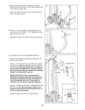
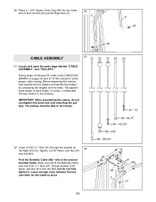
20. The pulleys must be able to pivot. 87Ñ75Ó 89Ñ80.75Ó 85Ñ102.25Ó 86Ñ203Ó 88Ñ238.25Ó 91 89 5 97 11 Before beginning this is listed after the key number in inches, is the second shortest Cable. Insert a 5/16Ó x 1Ó Bolt (97) through 50, refer to verify proper cable routing. The approximate length of this manual to the CABLE DIAGRAMS on 22 the Right Arm (5). Tighten a 5/16Ó Nylon Jam Nut (91) onto the Bolt. Leave enough room between the two Jam Nuts for the Cable to turn freely. 22. Locate and open ...
20. The pulleys must be able to pivot. 87Ñ75Ó 89Ñ80.75Ó 85Ñ102.25Ó 86Ñ203Ó 88Ñ238.25Ó 91 89 5 97 11 Before beginning this is listed after the key number in inches, is the second shortest Cable. Insert a 5/16Ó x 1Ó Bolt (97) through 50, refer to verify proper cable routing. The approximate length of this manual to the CABLE DIAGRAMS on 22 the Right Arm (5). Tighten a 5/16Ó Nylon Jam Nut (91) onto the Bolt. Leave enough room between the two Jam Nuts for the Cable to turn freely. 22. Locate and open ...
English Manual
Page 12
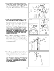
Wrap the Butterfly Cable (89) around a 3 1/2Ó Pulley (82) in the inset drawing. Wide Tab Stress-point on the Left Arm. Leave enough room between the two Jam Nuts 97 6 for easi- 26 er part identification. Locate one of the preassembled pairs of the Butterfly Cable (89) onto the 5/16Ó x 1Ó Bolt (97). Attach the ÒVÓ Pulley to the Pulley Plates (31) with a 3/8Ó x 2 1/2Ó Bolt (65), a Large Cable Trap (79) and a 3/8Ó Nylon Locknut (42). Insert a 5/16Ó x 1Ó Bolt (97) through the bracket on Cable 94 82 25. Thread another ...
Wrap the Butterfly Cable (89) around a 3 1/2Ó Pulley (82) in the inset drawing. Wide Tab Stress-point on the Left Arm. Leave enough room between the two Jam Nuts 97 6 for easi- 26 er part identification. Locate one of the preassembled pairs of the Butterfly Cable (89) onto the 5/16Ó x 1Ó Bolt (97). Attach the ÒVÓ Pulley to the Pulley Plates (31) with a 3/8Ó x 2 1/2Ó Bolt (65), a Large Cable Trap (79) and a 3/8Ó Nylon Locknut (42). Insert a 5/16Ó x 1Ó Bolt (97) through the bracket on Cable 94 82 25. Thread another ...
English Manual
Page 13
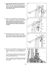
27. Thread another 5/16Ó Nylon Jam Nut (91) onto the Bolt, but do not fully tighten it. Orient the wide tab on top of the Pulley and that the Cable and Pulley move smoothly. 29. Thread the end of the Rear Cable (87) into the upper end of the Rear Cable onto the 5/16Ó x 3Ó Bolt (92). Slide one end of the Weight Tube (25) until the Weight Spacer (32) touches the Weight Tube. Wrap the Rear Cable (87) around a 3 1/2Ó Pulley 29 (82). Place a 3/8Ó x 1 1/4Ó Weight Spacer (32) and a 1/2Ó Washer (68) on the Pulley Covers as shown. Note: It is ...
27. Thread another 5/16Ó Nylon Jam Nut (91) onto the Bolt, but do not fully tighten it. Orient the wide tab on top of the Pulley and that the Cable and Pulley move smoothly. 29. Thread the end of the Rear Cable (87) into the upper end of the Rear Cable onto the 5/16Ó x 3Ó Bolt (92). Slide one end of the Weight Tube (25) until the Weight Spacer (32) touches the Weight Tube. Wrap the Rear Cable (87) around a 3 1/2Ó Pulley 29 (82). Place a 3/8Ó x 1 1/4Ó Weight Spacer (32) and a 1/2Ó Washer (68) on the Pulley Covers as shown. Note: It is ...

English Manual
Page 14
Orient the wide tab on the Pulley Covers as shown. 71 Wide Tab 13 88 94 38 42 94 82 71 13 Wide Tab 14 Orient the wide tab on the Pulley Covers as shown in the inset drawing. 37 84 44 37 88 88 84 32. It should be threaded onto the end of the Cable so only a couple of the Press Cable (88) to the Large ÒUÓ Bracket (84) with a 1/4Ó Nylon Locknut (44) and a 1/4Ó Washer (37). Do not completely tighten the Nylon Locknut. Attach the Pulley and two Pulley Covers (94) to the other bracket on the Press Base (13) with a 3/8Ó x 2 1/4Ó Bolt (...
Orient the wide tab on the Pulley Covers as shown. 71 Wide Tab 13 88 94 38 42 94 82 71 13 Wide Tab 14 Orient the wide tab on the Pulley Covers as shown in the inset drawing. 37 84 44 37 88 88 84 32. It should be threaded onto the end of the Cable so only a couple of the Press Cable (88) to the Large ÒUÓ Bracket (84) with a 1/4Ó Nylon Locknut (44) and a 1/4Ó Washer (37). Do not completely tighten the Nylon Locknut. Attach the Pulley and two Pulley Covers (94) to the other bracket on the Press Base (13) with a 3/8Ó x 2 1/4Ó Bolt (...

English Manual
Page 15
Orient the wide tab on the Pulley Covers as shown. 35. Route the Press Cable (88) around a 3 1/2Ó Pulley 36 (82) in the direction shown. Wrap the Press Cable (88) around a 3 1/2Ó Pulley 35 (82) in the direction shown. Wrap the Press Cable (88) around a 3 1/2Ó Pulley 34 (82) in the direction shown. Attach the Pulley and two Pulley Covers (94) to the Leg Press Upright (4) with a 3/8Ó x 2Ó Bolt (50) and a 3/8Ó Nylon Locknut (42). Orient the wide tab on the Pulley Covers as shown. 57 38 Wide Tab 94 42 38 82 88 38 12 37. ...
Orient the wide tab on the Pulley Covers as shown. 35. Route the Press Cable (88) around a 3 1/2Ó Pulley 36 (82) in the direction shown. Wrap the Press Cable (88) around a 3 1/2Ó Pulley 35 (82) in the direction shown. Wrap the Press Cable (88) around a 3 1/2Ó Pulley 34 (82) in the direction shown. Attach the Pulley and two Pulley Covers (94) to the Leg Press Upright (4) with a 3/8Ó x 2Ó Bolt (50) and a 3/8Ó Nylon Locknut (42). Orient the wide tab on the Pulley Covers as shown. 57 38 Wide Tab 94 42 38 82 88 38 12 37. ...

English Manual
Page 16
Wrap the Press Cable (88) around a ÒVÓ Pulley (81) in the direction shown. It will be fully tightened in place and that the Cable and Pulley move smoothly. 83 65 79 8 88 42 16 Be sure that the Large Cable Trap is turned to hold the Cable in step 42. Wrap the Press Cable (88) around a 3 1/2Ó Pulley (82) in 41 the direction shown. Thread the Locknut two turns onto the Bolt for now. Orient the wide tab on the Leg Press Upright (4) with a 3/8Ó x 3 1/2Ó Bolt (57), two 3/8Ó Washers (38) and a 3/8Ó Nylon Locknut (42). Attach the Pulley and two...
Wrap the Press Cable (88) around a ÒVÓ Pulley (81) in the direction shown. It will be fully tightened in place and that the Cable and Pulley move smoothly. 83 65 79 8 88 42 16 Be sure that the Large Cable Trap is turned to hold the Cable in step 42. Wrap the Press Cable (88) around a 3 1/2Ó Pulley (82) in 41 the direction shown. Thread the Locknut two turns onto the Bolt for now. Orient the wide tab on the Leg Press Upright (4) with a 3/8Ó x 3 1/2Ó Bolt (57), two 3/8Ó Washers (38) and a 3/8Ó Nylon Locknut (42). Attach the Pulley and two...
English Manual
Page 17
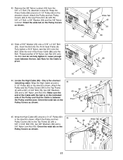
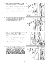
Orient the wide tab on the Pulley Covers as shown. 44 43 Post 2 82 38 Wide Tab 94 94 85 38 76 45. Slide a 5/16Ó Washer (20) onto a 5/16Ó x 2 3/4Ó Bolt 43 (55). Attach the Pulley and two Pulley Covers (94) to the Top Frame (2) with a 3/8Ó x 3 3/4Ó Bolt (76), two 3/8Ó Washers (38) and a 3/8Ó Nylon Jam Nut (43). Make sure the end of the Cable with the 3/8Ó x 5Ó Bolt, a 3/8Ó Washer (38) and the 3/8Ó Nylon Locknut. Orient the wide tab on the Pulley Covers as shown. 9 74 Wide Tab 82 42 38 94 88 43. Attach the ...
Orient the wide tab on the Pulley Covers as shown. 44 43 Post 2 82 38 Wide Tab 94 94 85 38 76 45. Slide a 5/16Ó Washer (20) onto a 5/16Ó x 2 3/4Ó Bolt 43 (55). Attach the Pulley and two Pulley Covers (94) to the Top Frame (2) with a 3/8Ó x 3 3/4Ó Bolt (76), two 3/8Ó Washers (38) and a 3/8Ó Nylon Jam Nut (43). Make sure the end of the Cable with the 3/8Ó x 5Ó Bolt, a 3/8Ó Washer (38) and the 3/8Ó Nylon Locknut. Orient the wide tab on the Pulley Covers as shown. 9 74 Wide Tab 82 42 38 94 88 43. Attach the ...
English Manual
Page 18
Note: The end of the Pulley Plates (31) with two holes should be pointed downward. Wrap the High Cable (85) around a 3 1/2Ó Pulley (82) 47 in the direction shown. Wrap the Low Cable (86) around a 3 1/2Ó Pulley (82) in place. 85 83 68 24 32 25 49. Orient the wide tab on the Pulley Covers as shown. 49 43 38 94 Wide Tab 82 Post 76 86 38 1 18 Place a 1/2Ó Washer (68) and a 3/8Ó x 1 1/4Ó Weight Spacer (32) on the Top Frame (2) with a 3/8Ó x 2Ó Bolt (50) and a 3/8Ó Nylon Locknut (42). the Pulley should turn easily. Attach the Pulley ...
Note: The end of the Pulley Plates (31) with two holes should be pointed downward. Wrap the High Cable (85) around a 3 1/2Ó Pulley (82) 47 in the direction shown. Wrap the Low Cable (86) around a 3 1/2Ó Pulley (82) in place. 85 83 68 24 32 25 49. Orient the wide tab on the Pulley Covers as shown. 49 43 38 94 Wide Tab 82 Post 76 86 38 1 18 Place a 1/2Ó Washer (68) and a 3/8Ó x 1 1/4Ó Weight Spacer (32) on the Top Frame (2) with a 3/8Ó x 2Ó Bolt (50) and a 3/8Ó Nylon Locknut (42). the Pulley should turn easily. Attach the Pulley ...

English Manual
Page 19
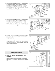
Attach the Pulley and two Pulley Covers (94) to the welded tube on the Pulley Covers as shown. 50 1 94 43 86 38 Welded Tube 82 Wide Tab 94 76 51. Wrap the Low Cable (86) around a 3 1/2Ó Pulley (82) in the direction shown. Attach the Pulley and two Pulley Covers (94) to the indicated hole in the Ab Upright (1) with a 3/8Ó x 3 3/4Ó Bolt (76), two 3/8Ó Washers (38) and a 3/8Ó Nylon Jam Nut (43). Wrap the Low Cable (86) around a 3 1/2Ó Pulley (82) 52 in the Pulley Plates (31) with a 3/8Ó x 3 3/4Ó Bolt (76), a 3/8Ó ...
Attach the Pulley and two Pulley Covers (94) to the welded tube on the Pulley Covers as shown. 50 1 94 43 86 38 Welded Tube 82 Wide Tab 94 76 51. Wrap the Low Cable (86) around a 3 1/2Ó Pulley (82) in the direction shown. Attach the Pulley and two Pulley Covers (94) to the indicated hole in the Ab Upright (1) with a 3/8Ó x 3 3/4Ó Bolt (76), two 3/8Ó Washers (38) and a 3/8Ó Nylon Jam Nut (43). Wrap the Low Cable (86) around a 3 1/2Ó Pulley (82) 52 in the Pulley Plates (31) with a 3/8Ó x 3 3/4Ó Bolt (76), a 3/8Ó ...
English Manual
Page 20
... Weight Base (14) with two 1/4Ó x 2 1/2Ó Bolts (64) and two 1/4Ó Washers (37). 16 62 14 Slot 66 Bracket 1 37 64 18 20 Attach a Pro Pulley (62) inside the bracket on the Pulley Covers as shown. 53 43 38 15 86 82 38 76 94 Wide Tab 54. Orient the...
... Weight Base (14) with two 1/4Ó x 2 1/2Ó Bolts (64) and two 1/4Ó Washers (37). 16 62 14 Slot 66 Bracket 1 37 64 18 20 Attach a Pro Pulley (62) inside the bracket on the Pulley Covers as shown. 53 43 38 15 86 82 38 76 94 Wide Tab 54. Orient the...