
English Manual
Page 2
... Assembly 4 Cable Diagrams 23 Adjustment 25 Trouble-shooting and Maintenance 26 Weight Resistance Chart 27 Ordering Replacement Parts Back Cover Full 90-day Warranty Back Cover Note: A PART LIST/EXPLODED DRAWING and a PART IDENTIFICATION CHART are attached in the center of 12 and pets away from the home gym at all ...times. 10. Remove the PART LIST/EXPLODED DRAWING and the PART IDENTIFICATION CHART before using the home gym. 1. Make sure the cables remain on all times. Keep hands and feet away from the...
... Assembly 4 Cable Diagrams 23 Adjustment 25 Trouble-shooting and Maintenance 26 Weight Resistance Chart 27 Ordering Replacement Parts Back Cover Full 90-day Warranty Back Cover Note: A PART LIST/EXPLODED DRAWING and a PART IDENTIFICATION CHART are attached in the center of 12 and pets away from the home gym at all ...times. 10. Remove the PART LIST/EXPLODED DRAWING and the PART IDENTIFICATION CHART before using the home gym. 1. Make sure the cables remain on all times. Keep hands and feet away from the...

English Manual
Page 3
...on a decal attached to develop every major muscle group of this manual carefully before calling. The WEIDER® PRO 9940 offers a unique selection of weight stations designed to the WEIDER® PRO 9940 Home Gym (see the front cover of the body. If you have additional questions, please ... Seat Low Pulley Station Foot Plate Weight Stacks Leg Press Lever 3 For your cardiovascular system, the WEIDER® PRO 9940 makes it easy to familiarize yourself with the major parts and how they fit together. To help us assist you for selecting the innovative and versatile...
...on a decal attached to develop every major muscle group of this manual carefully before calling. The WEIDER® PRO 9940 offers a unique selection of weight stations designed to the WEIDER® PRO 9940 Home Gym (see the front cover of the body. If you have additional questions, please ... Seat Low Pulley Station Foot Plate Weight Stacks Leg Press Lever 3 For your cardiovascular system, the WEIDER® PRO 9940 makes it easy to familiarize yourself with the major parts and how they fit together. To help us assist you for selecting the innovative and versatile...

English Manual
Page 4
...that by setting aside plenty of time, and by deciding to make the assembly process as smooth as possible, we have included a PART IDENTIFICATION CHART located in a cleared area and remove the packing materials. Most people find that your body while you are oriented as .... The Four Stages of the Assembly Process Frame Assembly You will begin the assembly process itself, take time-possibly several hours. Place all parts are exercising. 4 Some assembly steps require two people. Giving Yourself a Good Start Before you begin by anyone. Arm Assembly This assembly...
...that by setting aside plenty of time, and by deciding to make the assembly process as smooth as possible, we have included a PART IDENTIFICATION CHART located in a cleared area and remove the packing materials. Most people find that your body while you are oriented as .... The Four Stages of the Assembly Process Frame Assembly You will begin the assembly process itself, take time-possibly several hours. Place all parts are exercising. 4 Some assembly steps require two people. Giving Yourself a Good Start Before you begin by anyone. Arm Assembly This assembly...
English Manual
Page 5
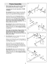
... 1b 89 93 64 64 4 5 2a 5 24 63 57 57 63 28 6 92 102 92 101 2b 64 5 64 93 6 89 5 Locate and open the parts bag labeled "FRAME ASSEMBLY." See drawing 1b. Note: There are using. 2. Press a 2" Square Inner Cap (28) into each end of the Press Base (6). See drawing...
... 1b 89 93 64 64 4 5 2a 5 24 63 57 57 63 28 6 92 102 92 101 2b 64 5 64 93 6 89 5 Locate and open the parts bag labeled "FRAME ASSEMBLY." See drawing 1b. Note: There are using. 2. Press a 2" Square Inner Cap (28) into each end of the Press Base (6). See drawing...
English Manual
Page 10
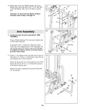
Locate and open the parts bag labeled "ARM ASSEMBLY." Press a 1 3/4" Square Inner Cap (35) into the indicated hole in steps 1 through 15. 15 59 48 59 15 50 50 48 ...
Locate and open the parts bag labeled "ARM ASSEMBLY." Press a 1 3/4" Square Inner Cap (35) into the indicated hole in steps 1 through 15. 15 59 48 59 15 50 50 48 ...

English Manual
Page 11
... (10) with a 3/8" x 1" Bolt (84) and two 3/8" Nylon Jamnuts (63). Locate and open the parts bag labeled "PULLEY 20 BAG 2." Attach the Butterfly Cable to assemble the Left Butterfly Arm (10, not shown).... Secure the Butterfly Arm with a hammer. Make sure the teeth on each end of the Pro Pulley. For Cable identification and routing during steps 19 to 49, refer to the bracket on pages ...23 and 24. Locate and open the parts bag labeled "CABLE 19 ASSEMBLY." Identify the Butterfly Cable (73). Press a 1 3/4" Square Inner Cap ...
... (10) with a 3/8" x 1" Bolt (84) and two 3/8" Nylon Jamnuts (63). Locate and open the parts bag labeled "PULLEY 20 BAG 2." Attach the Butterfly Cable to assemble the Left Butterfly Arm (10, not shown).... Secure the Butterfly Arm with a hammer. Make sure the teeth on each end of the Pro Pulley. For Cable identification and routing during steps 19 to 49, refer to the bracket on pages ...23 and 24. Locate and open the parts bag labeled "CABLE 19 ASSEMBLY." Identify the Butterfly Cable (73). Press a 1 3/4" Square Inner Cap ...
English Manual
Page 14
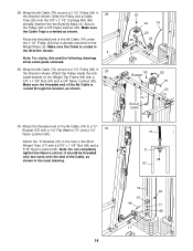
... 29 the direction shown. Make sure the Cable Trap is routed in the direction shown. 4 Note: For clarity, this and the following drawings show some parts removed. 29. Make sure the threaded end of the Cable, as shown. 30. Note: Do not completely tighten the Nylon Locknut; 28. Slide the Pulley...
... 29 the direction shown. Make sure the Cable Trap is routed in the direction shown. 4 Note: For clarity, this and the following drawings show some parts removed. 29. Make sure the threaded end of the Cable, as shown. 30. Note: Do not completely tighten the Nylon Locknut; 28. Slide the Pulley...

English Manual
Page 20
... in the Butterfly Upright (2) and secure it with two 1/4" x 2 1/2" Bolts (79) and two 1/4" Flat Washers (71). 12 1 79 71 79 51. Locate and open the parts bag labeled "SEAT ASSEMBLY." Secure the other end of the Press Backrest (99) with two 1/4" x 3/4" Bolts (49). Insert the 1/4" x 2 1/2" Carriage Bolt (45) into the indicated...
... in the Butterfly Upright (2) and secure it with two 1/4" x 2 1/2" Bolts (79) and two 1/4" Flat Washers (71). 12 1 79 71 79 51. Locate and open the parts bag labeled "SEAT ASSEMBLY." Secure the other end of the Press Backrest (99) with two 1/4" x 3/4" Bolts (49). Insert the 1/4" x 2 1/2" Carriage Bolt (45) into the indicated...
English Manual
Page 22
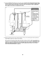
... few times to remove the slack by tightening the cables. See TROUBLESHOOTING AND MAINTENANCE on page 25 of the remaining parts will need to make sure that all parts have been attached to order a replacement decal. If there is any slack in the cables, you will be damaged ...this manual. IMPORTANT: If the cables are not properly installed, they may be explained in the locations shown. Apply the WEIDER PRO 9940 decal in the appropriate location. 56 WEIDER PRO 9940 57. Make sure that the cables move smoothly, find and correct the problem. The use of this manual to the...
... few times to remove the slack by tightening the cables. See TROUBLESHOOTING AND MAINTENANCE on page 25 of the remaining parts will need to make sure that all parts have been attached to order a replacement decal. If there is any slack in the cables, you will be damaged ...this manual. IMPORTANT: If the cables are not properly installed, they may be explained in the locations shown. Apply the WEIDER PRO 9940 decal in the appropriate location. 56 WEIDER PRO 9940 57. Make sure that the cables move smoothly, find and correct the problem. The use of this manual to the...

English Manual
Page 25
...) to the Press Cable (72) with a Cable Clip (69). For some exercises, the Chain (67) should be adjusted. Adjustment The instructions below describe how each part of the home gym can be set up one of the adjustment holes in the Adjustment Tube with the hole in the bracket and re...
...) to the Press Cable (72) with a Cable Clip (69). For some exercises, the Chain (67) should be adjusted. Adjustment The instructions below describe how each part of the home gym can be set up one of the adjustment holes in the Adjustment Tube with the hole in the bracket and re...

English Manual
Page 26
...Note: Begin by inserting the Adjustment Knob (103) at the desired height. 105 104 28 103 20 Trouble-shooting and Maintenance Inspect and tighten all parts each time you use the home gym. If there is slack in several sets of cable used . Re-attach the Pulley and Cable Trap to... hole in the Seat Frame. To use solvents. Secure the Curl Pad by moving the "V"- 7 Pulley one hole, and then one Pulley to any worn parts immediately. The home gym can move a Pulley (24), remove the 3/8" Nylon Locknut (50) and the 3/8" x 2" Bolt (54). To move the "V"-Pulley to the second ...
...Note: Begin by inserting the Adjustment Knob (103) at the desired height. 105 104 28 103 20 Trouble-shooting and Maintenance Inspect and tighten all parts each time you use the home gym. If there is slack in several sets of cable used . Re-attach the Pulley and Cable Trap to... hole in the Seat Frame. To use solvents. Secure the Curl Pad by moving the "V"- 7 Pulley one hole, and then one Pulley to any worn parts immediately. The home gym can move a Pulley (24), remove the 3/8" Nylon Locknut (50) and the 3/8" x 2" Bolt (54). To move the "V"-Pulley to the second ...

English Manual
Page 29
Part Identification Chart-Model No. 831.159730 R0800A 1/4" Nylon Locknut (68) 5/16" Nylon Locknut (64) 5/16" x 1 3/4" Bolt (96) 3/8" Nylon Locknut (50) 3/8" Nylon Jamnut (63) 5/16" x 2 1/2" Bolt (...
Part Identification Chart-Model No. 831.159730 R0800A 1/4" Nylon Locknut (68) 5/16" Nylon Locknut (64) 5/16" x 1 3/4" Bolt (96) 3/8" Nylon Locknut (50) 3/8" Nylon Jamnut (63) 5/16" x 2 1/2" Bolt (...

English Manual
Page 30
...Adjustable Pulley Plate 77 2 Press Arm 24 20 3 1/2" Pulley 78 1 3/8" x 4" Bolt 25 16 Cable Trap 79 5 1/4" x 2 1/2" Bolt 26 2 Pro Pulley 80 1 1" Tap Screw 27 4 "V"-Pulley 81 1 Ab Strap 28 13 2" Square Inner Cap 82 2 4 1/2" Pulley 29 2 Butterfly Foam Pad 83 1...Pad 52 1 3/8" x 8" Bolt # 1 User's Manual 53 2 3/8" x 2 1/2" Bolt # 1 Exercise Poster 54 4 3/8" x 2" Bolt Note: "#" indicates a non-illustrated part. Specifications are subject to change without notice. Qty. Part List-Model No. 831.159730 R0800A Key No. Qty. Description Key No.
...Adjustable Pulley Plate 77 2 Press Arm 24 20 3 1/2" Pulley 78 1 3/8" x 4" Bolt 25 16 Cable Trap 79 5 1/4" x 2 1/2" Bolt 26 2 Pro Pulley 80 1 1" Tap Screw 27 4 "V"-Pulley 81 1 Ab Strap 28 13 2" Square Inner Cap 82 2 4 1/2" Pulley 29 2 Butterfly Foam Pad 83 1...Pad 52 1 3/8" x 8" Bolt # 1 User's Manual 53 2 3/8" x 2 1/2" Bolt # 1 Exercise Poster 54 4 3/8" x 2" Bolt Note: "#" indicates a non-illustrated part. Specifications are subject to change without notice. Qty. Part List-Model No. 831.159730 R0800A Key No. Qty. Description Key No.

English Manual
Page 32
...Central Time (excluding holidays) The model number and serial number of this manual). When requesting help assembling or operating the WEIDER® PRO 9940 Home Gym • a part is used commercially or for immediate purchase or special order when you may also have other rights which vary from the date...• The MODEL NUMBER of the product (831.159730) • The NAME of the product (WEIDER® PRO 9940 Home Gym) • The KEY NUMBER and DESCRIPTION of the PART (see the PART LIST/EXPLODED DRAWING in Canada © 1999 Sears, Roebuck and Co. This warranty gives you specific ...
...Central Time (excluding holidays) The model number and serial number of this manual). When requesting help assembling or operating the WEIDER® PRO 9940 Home Gym • a part is used commercially or for immediate purchase or special order when you may also have other rights which vary from the date...• The MODEL NUMBER of the product (831.159730) • The NAME of the product (WEIDER® PRO 9940 Home Gym) • The KEY NUMBER and DESCRIPTION of the PART (see the PART LIST/EXPLODED DRAWING in Canada © 1999 Sears, Roebuck and Co. This warranty gives you specific ...


