
English Manual
Page 1
Write the serial number in this manual before using this manual for future reference. Serial Number Decal USERʼS MANUAL SEARS, ROEBUCK AND CO., HOFFMAN ESTATES, IL 60179 CAUTION Read all precautions and instructions in the space above for future reference. Keep this equipment. Visit our website at www.weslo.com new products, prizes, fitness tips, and much more! Model No. 831.283500 Serial No.
Write the serial number in this manual before using this manual for future reference. Serial Number Decal USERʼS MANUAL SEARS, ROEBUCK AND CO., HOFFMAN ESTATES, IL 60179 CAUTION Read all precautions and instructions in the space above for future reference. Keep this equipment. Visit our website at www.weslo.com new products, prizes, fitness tips, and much more! Model No. 831.283500 Serial No.
English Manual
Page 2
TABLE OF CONTENTS IMPORTANT PRECAUTIONS 3 BEFORE YOU BEGIN 4 ASSEMBLY 5 HOW TO USE THE ELLIPTICAL CROSSTRAINER 9 MAINTENANCE AND TROUBLESHOOTING 11 CONDITIONING GUIDELINES 13 PART LIST 14 EXPLODED DRAWING 15 HOW TO ORDER REPLACEMENT PARTS Back Cover FULL 90-DAY WARRANTY Back Cover 2
TABLE OF CONTENTS IMPORTANT PRECAUTIONS 3 BEFORE YOU BEGIN 4 ASSEMBLY 5 HOW TO USE THE ELLIPTICAL CROSSTRAINER 9 MAINTENANCE AND TROUBLESHOOTING 11 CONDITIONING GUIDELINES 13 PART LIST 14 EXPLODED DRAWING 15 HOW TO ORDER REPLACEMENT PARTS Back Cover FULL 90-DAY WARRANTY Back Cover 2
English Manual
Page 3
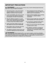
... reduce the risk of all instructions in a commercial, rental, or institutional setting. It is the responsibility of the owner to ensure that all users of the elliptical crosstrainer are adequately informed of serious injury, read the following important precau- Replace any exercise program, consult your back. 10. The elliptical crosstrainer should not be used by or through the use the elliptical crosstrainer in this manual before using the elliptical crosstrainer.
... reduce the risk of all instructions in a commercial, rental, or institutional setting. It is the responsibility of the owner to ensure that all users of the elliptical crosstrainer are adequately informed of serious injury, read the following important precau- Replace any exercise program, consult your back. 10. The elliptical crosstrainer should not be used by or through the use the elliptical crosstrainer in this manual before using the elliptical crosstrainer.
English Manual
Page 4
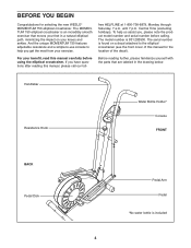
...). Handlebar Resistance Knob Water Bottle Holder* Console FRONT BACK Pedal Disk Pedal Arm Pedal *No water bottle is found on your benefit, read this manual, please call our toll- And the unique MOMENTUM 750 features adjustable resistance and a simple-to-use console to the elliptical crosstrainer (see the front cover of the decal). free HELPLINE at 1-800-736-6879, Monday through Saturday, 7 a.m. The model number is an incredibly smooth exerciser that...
...). Handlebar Resistance Knob Water Bottle Holder* Console FRONT BACK Pedal Disk Pedal Arm Pedal *No water bottle is found on your benefit, read this manual, please call our toll- And the unique MOMENTUM 750 features adjustable resistance and a simple-to-use console to the elliptical crosstrainer (see the front cover of the decal). free HELPLINE at 1-800-736-6879, Monday through Saturday, 7 a.m. The model number is an incredibly smooth exerciser that...
English Manual
Page 5
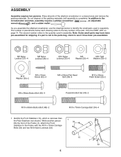
... (38)-4 M10 Nylon Locknut (33)-6 M6 Washer (25)-4 M10 Split Washer (59)-2 M10 Washer (35)-2 M4 x 16mm Screw (42)-4 M6 x 54mm Flat Head Bolt (36)-4 M10 x 25mm Patch Screw (22)-2 M8 x 38mm Button Bolt (50)-4 Pedal Arm Bolt Set (40)-2 M10 x 66mm Button Bolt (48)-2 M10 x 75mm Carriage Bolt (34)-4 1. Place all parts of the part, from the PART LIST on page 14. ASSEMBLY Assembly requires two persons.
... (38)-4 M10 Nylon Locknut (33)-6 M6 Washer (25)-4 M10 Split Washer (59)-2 M10 Washer (35)-2 M4 x 16mm Screw (42)-4 M6 x 54mm Flat Head Bolt (36)-4 M10 x 25mm Patch Screw (22)-2 M8 x 38mm Button Bolt (50)-4 Pedal Arm Bolt Set (40)-2 M10 x 66mm Button Bolt (48)-2 M10 x 75mm Carriage Bolt (34)-4 1. Place all parts of the part, from the PART LIST on page 14. ASSEMBLY Assembly requires two persons.
English Manual
Page 6
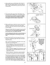
... Lower Cable (55) as shown by the diagram inside the battery compartment. 3 23 33 28 34 Batteries 4. Slide the Upright (2) onto the Frame. Turn the Resistance Knob (63) counterclockwise to the lowest setting before continuing to drawing A. Pull up on the metal bracket on the upper end of the Frame (1), attach the Rear Stabilizer (28) to the Upright (2) with two M10 x 75mm Carriage Bolts...
... Lower Cable (55) as shown by the diagram inside the battery compartment. 3 23 33 28 34 Batteries 4. Slide the Upright (2) onto the Frame. Turn the Resistance Knob (63) counterclockwise to the lowest setting before continuing to drawing A. Pull up on the metal bracket on the upper end of the Frame (1), attach the Rear Stabilizer (28) to the Upright (2) with two M10 x 75mm Carriage Bolts...

English Manual
Page 7
... (38). Repeat this step to the Handlebar Arm with a 6 sticker. Slide a Handlebar Spacer (47) and the Left Handlebar onto the left axle on the indicated side. Make sure that the Nylon Locknuts are on the Upright (2). Identify the Left Pedal Arm (11). Do not fully tighten the Button Bolts yet. Attach the Left Handlebar to assemble the Right Handlebar (8) and...
... (38). Repeat this step to the Handlebar Arm with a 6 sticker. Slide a Handlebar Spacer (47) and the Left Handlebar onto the left axle on the indicated side. Make sure that the Nylon Locknuts are on the Upright (2). Identify the Left Pedal Arm (11). Do not fully tighten the Button Bolts yet. Attach the Left Handlebar to assemble the Right Handlebar (8) and...
English Manual
Page 8
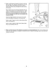
... Arm (5) inside of the elliptical crosstrainer in the same way. 16 Grease 40 Refer to step 5. Make sure that all parts of grease to the left over after assembly is completed. the Handlebar Arm must pivot freely. Attach the Left 5 Pedal Arm to the axle on the Left Pedal Arm (11). Tighten the M10 x 66mm Button Bolts (48) in the Handlebar Arms (5). 40 11 22 35 9. Refer to a Pedal Arm Bolt Set...
... Arm (5) inside of the elliptical crosstrainer in the same way. 16 Grease 40 Refer to step 5. Make sure that all parts of grease to the left over after assembly is completed. the Handlebar Arm must pivot freely. Attach the Left 5 Pedal Arm to the axle on the Left Pedal Arm (11). Tighten the M10 x 66mm Button Bolts (48) in the Handlebar Arms (5). 40 11 22 35 9. Refer to a Pedal Arm Bolt Set...
English Manual
Page 9
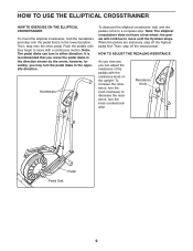
... flywheel stops. HOW TO ADJUST THE PEDALING RESISTANCE As you exercise, you can turn the knob clockwise; the pedals will continue to decrease the resistance, turn the knob counterclockwise. To increase the resistance, turn in either direction. Note: The pedal disks can adjust the resistance of the pedals with a continuous motion. Resistance Knob Pedal Pedal Disk 9 Then, step off the highest pedal first. Then, step onto the other pedal. Note: The elliptical crosstrainer does not have a free wheel; to move...
... flywheel stops. HOW TO ADJUST THE PEDALING RESISTANCE As you exercise, you can turn the knob clockwise; the pedals will continue to decrease the resistance, turn the knob counterclockwise. To increase the resistance, turn in either direction. Note: The pedal disks can adjust the resistance of the pedals with a continuous motion. Resistance Knob Pedal Pedal Disk 9 Then, step off the highest pedal first. Then, step onto the other pedal. Note: The elliptical crosstrainer does not have a free wheel; to move...
English Manual
Page 10
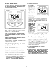
... the scan mode. Speed, time, distance, or calorie mode-To select one of measurement, press the On/Reset button for continuous display, repeatedly press the Mode button. The letters mph or km/h will appear in the console (see BATTERY REPLACEMENT on , the scan mode will turn on the console, remove it may be selected automati- If the pedals are not moved and the console buttons are replaced, it . Speed-This mode displays your workouts. To turn off " feature...
... the scan mode. Speed, time, distance, or calorie mode-To select one of measurement, press the On/Reset button for continuous display, repeatedly press the Mode button. The letters mph or km/h will appear in the console (see BATTERY REPLACEMENT on , the scan mode will turn on the console, remove it may be selected automati- If the pedals are not moved and the console buttons are replaced, it . Speed-This mode displays your workouts. To turn off " feature...
English Manual
Page 11
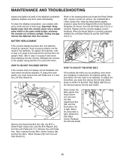
... the wires. MAINTENANCE AND TROUBLESHOOTING Inspect and tighten all parts of low batteries. Loosen, but do not remove, the indicated M4 x 16mm Screw (42). Replace any worn parts immediately. Remove the Left Pedal Arm. BATTERY REPLACEMENT If the console display becomes dim, the batteries should be replaced; Repeat until the 41 Drive Belt (19) is tight, tighten the 62 Flat Head Screw. Refer to step 4 on page 6 and remove the console from the Left Pedal Arm (11). Turn the...
... the wires. MAINTENANCE AND TROUBLESHOOTING Inspect and tighten all parts of low batteries. Loosen, but do not remove, the indicated M4 x 16mm Screw (42). Replace any worn parts immediately. Remove the Left Pedal Arm. BATTERY REPLACEMENT If the console display becomes dim, the batteries should be replaced; Repeat until the 41 Drive Belt (19) is tight, tighten the 62 Flat Head Screw. Refer to step 4 on page 6 and remove the console from the Left Pedal Arm (11). Turn the...
English Manual
Page 12
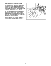
... too much resistance. To adjust the resistance strap, first remove the left pedal arm. 26 18 17 12 Close the Strap Clamp and turn the resistance knob to the lowest setting. Open the Strap Clamp (26) and pull the end of the Resistance Strap (18) downward slightly. When the resistance strap is properly adjusted, reattach the left side shield and the left side shield (see HOW TO ADJUST THE REED SWITCH on...
... too much resistance. To adjust the resistance strap, first remove the left pedal arm. 26 18 17 12 Close the Strap Clamp and turn the resistance knob to the lowest setting. Open the Strap Clamp (26) and pull the end of the Resistance Strap (18) downward slightly. When the resistance strap is properly adjusted, reattach the left side shield and the left side shield (see HOW TO ADJUST THE REED SWITCH on...
English Manual
Page 13
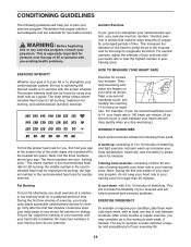
... of your exercise until your heart rate is between workouts. CONDITIONING GUIDELINES The following three parts: A warm-up, consisting of 5 to 10 minutes of your everyday life. 13 The chart below shows recommended heart rates for aerobic exercise. The three numbers are essential for longer than 20 minutes. For aerobic exercise, adjust the intensity of exercising with 5 to 10 minutes of exercise, your body uses easily...
... of your exercise until your heart rate is between workouts. CONDITIONING GUIDELINES The following three parts: A warm-up, consisting of 5 to 10 minutes of your everyday life. 13 The chart below shows recommended heart rates for aerobic exercise. The three numbers are essential for longer than 20 minutes. For aerobic exercise, adjust the intensity of exercising with 5 to 10 minutes of exercise, your body uses easily...
English Manual
Page 14
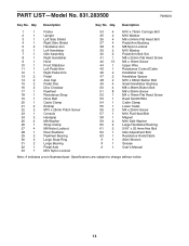
... x 38mm Button Bolt 51 8 M6 x 35mm Screw 52 1 M4 x 16mm Flat Head Screw 53 1 Reed Switch/Wire 54 1 Cable Clamp 55 1 Lower Cable 56 2 M4 x 25mm Screw 57 1 M10 Flat Head Bolt 58 1 Magnet 59 2 M10 Split Washer 60 4 Large Handlebar Bushing 61 2 5/16" x 25.4mm Hex Bolt 62 1 Idler Adjustment Bolt 63 1 Resistance Knob/Cable # 1 Allen Wrench # 1 Grease # 1 Userʼs Manual Note: # indicates a non-illustrated part. Qty. Specifications are subject to change without...
... x 38mm Button Bolt 51 8 M6 x 35mm Screw 52 1 M4 x 16mm Flat Head Screw 53 1 Reed Switch/Wire 54 1 Cable Clamp 55 1 Lower Cable 56 2 M4 x 25mm Screw 57 1 M10 Flat Head Bolt 58 1 Magnet 59 2 M10 Split Washer 60 4 Large Handlebar Bushing 61 2 5/16" x 25.4mm Hex Bolt 62 1 Idler Adjustment Bolt 63 1 Resistance Knob/Cable # 1 Allen Wrench # 1 Grease # 1 Userʼs Manual Note: # indicates a non-illustrated part. Qty. Specifications are subject to change without...
English Manual
Page 15
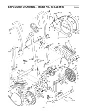
EXPLODED DRAWING-Model No. 831.283500 R0802A 42 42 46 42 24 4 42 42 24 8 56 23 42 3 46 42 50 5 60 6 38 49 14 60 42 49 47 33 44 21 49 47 49 14 42 63 36 45 50 40 42 38 2 59 48 59 60 13 40 5 12 25 27 35 22 25 60 37 17 39 20 18 27 37 51 34 21 40 10 36 13 11 40 25 27 35 37 51 22 55 29 39 57 52 26 58 33 33 29 9 16 30 61 31 3742 33 41 53 54 31 1 32 61 30 16 7 38 33 33 28 51 15 21 19 51 15 21 34 62 51 15
EXPLODED DRAWING-Model No. 831.283500 R0802A 42 42 46 42 24 4 42 42 24 8 56 23 42 3 46 42 50 5 60 6 38 49 14 60 42 49 47 33 44 21 49 47 49 14 42 63 36 45 50 40 42 38 2 59 48 59 60 13 40 5 12 25 27 35 22 25 60 37 17 39 20 18 27 37 51 34 21 40 10 36 13 11 40 25 27 35 37 51 22 55 29 39 57 52 26 58 33 33 29 9 16 30 61 31 3742 33 41 53 54 31 1 32 61 30 16 7 38 33 33 28 51 15 21 19 51 15 21 34 62 51 15
English Manual
Page 16
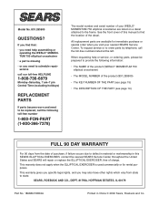
...? This warranty does not apply when the ELLIPTICAL EXERCISER is missing • or you need to be prepared to provide the following toll-free number 1-800-FON-PART (1-800-366-7278) The model number and serial number of your nearest SEARS Service Center. If you find the location of this SEARS ELLIPTICAL EXERCISER, contact the nearest SEARS Service Center throughout the United States and SEARS will repair or replace the ELLIPTICAL EXERCISER, free of purchase...
...? This warranty does not apply when the ELLIPTICAL EXERCISER is missing • or you need to be prepared to provide the following toll-free number 1-800-FON-PART (1-800-366-7278) The model number and serial number of your nearest SEARS Service Center. If you find the location of this SEARS ELLIPTICAL EXERCISER, contact the nearest SEARS Service Center throughout the United States and SEARS will repair or replace the ELLIPTICAL EXERCISER, free of purchase...


