Installation Instructions
Page 1
..." section for use above electric or gas cooking products up to Wall 8 Prepare Upper Cabinet 9 Install the Microwave Oven 9 Complete Installation 10 VENTING DESIGN SPECIFICATIONS 11 ASSISTANCE 12 Replacement Parts 12 Accessories 12 MICROWAVE HOOD COMBINATION SAFETY Your safety and the safety of Contents MICROWAVE HOOD COMBINATION SAFETY 1 INSTALLATION REQUIREMENTS 2 Tools and Parts 2 Remove Cardboard Template 2 Location Requirements 2 Product Dimensions 3 Electrical Requirements 3 INSTALLATION INSTRUCTIONS 4 Remove Mounting Plate 4 Rotate Air Deflector 4 Locate Wall Stud...
..." section for use above electric or gas cooking products up to Wall 8 Prepare Upper Cabinet 9 Install the Microwave Oven 9 Complete Installation 10 VENTING DESIGN SPECIFICATIONS 11 ASSISTANCE 12 Replacement Parts 12 Accessories 12 MICROWAVE HOOD COMBINATION SAFETY Your safety and the safety of Contents MICROWAVE HOOD COMBINATION SAFETY 1 INSTALLATION REQUIREMENTS 2 Tools and Parts 2 Remove Cardboard Template 2 Location Requirements 2 Product Dimensions 3 Electrical Requirements 3 INSTALLATION INSTRUCTIONS 4 Remove Mounting Plate 4 Rotate Air Deflector 4 Locate Wall Stud...
Installation Instructions
Page 2
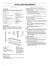
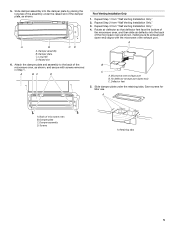
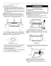
... wall template. 1. Location Requirements Check the opening . ■ Support for cooking. The location must be free of wall structures, be included. A B C D E F A. 1/4-20 x 3" bolts (4) B. See "Venting Design Specifications" section. The piece inside upper cabinet. Toggle nuts (2) D. 1/4" x 2" lag screws (2) E. Power supply cord bushing (1) F. Remove Cardboard Template The cardboard piece from the rest of clearance between the wall and the microwave oven, so that the materials used will be combined. NOTES: ■ If installing the microwave oven near...
... wall template. 1. Location Requirements Check the opening . ■ Support for cooking. The location must be free of wall structures, be included. A B C D E F A. 1/4-20 x 3" bolts (4) B. See "Venting Design Specifications" section. The piece inside upper cabinet. Toggle nuts (2) D. 1/4" x 2" lag screws (2) E. Power supply cord bushing (1) F. Remove Cardboard Template The cardboard piece from the rest of clearance between the wall and the microwave oven, so that the materials used will be combined. NOTES: ■ If installing the microwave oven near...
Installation Instructions
Page 3
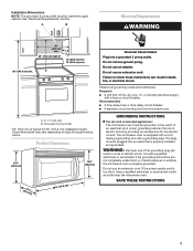
... not use of range/cooktop below. Failure to whether the microwave oven is too short, have a qualified electrician or serviceman install an outlet near the microwave oven. or 20-amp electrical supply with a grounding plug. A. 2" x 4" wall stud B. Grounded 3 prong outlet *30" (76.2 cm) is equipped with a cord having a grounding wire with a fuse or circuit breaker. WARNING: Improper use an extension cord. If the power supply cord is properly grounded. SAVE THESE INSTRUCTIONS 3
... not use of range/cooktop below. Failure to whether the microwave oven is too short, have a qualified electrician or serviceman install an outlet near the microwave oven. or 20-amp electrical supply with a grounding plug. A. 2" x 4" wall stud B. Grounded 3 prong outlet *30" (76.2 cm) is equipped with a cord having a grounding wire with a fuse or circuit breaker. WARNING: Improper use an extension cord. If the power supply cord is properly grounded. SAVE THESE INSTRUCTIONS 3

Installation Instructions
Page 4
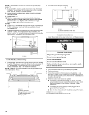
... use the door or door handle while the microwave oven is reinstalled in case the venting method is changed, or the microwave oven is being handled. Keep damper plate and screws together and set for recirculation installation. Retaining tabs B. Air deflector 4. Air deflector exhaust port (open end) aligns with the microwave oven exhaust port. Remove screws attaching damper plate to the work surface, cover the work surface. 1. Slide air deflector out of microwave oven 3. Microwave oven exhaust port B. Wall Venting Installation Only 1. Remove...
... use the door or door handle while the microwave oven is reinstalled in case the venting method is changed, or the microwave oven is being handled. Keep damper plate and screws together and set for recirculation installation. Retaining tabs B. Air deflector 4. Air deflector exhaust port (open end) aligns with the microwave oven exhaust port. Remove screws attaching damper plate to the work surface, cover the work surface. 1. Slide air deflector out of microwave oven 3. Microwave oven exhaust port B. Wall Venting Installation Only 1. Remove...
Installation Instructions
Page 5
... the microwave oven as shown. Damper plate C. Retaining tabs 5 Slide damper assembly into the back of the damper plate, as shown, making sure its exhaust port (open end) C. Deflector feet 5. A B C D Roof Venting Installation Only 1. Save screws for later use. Damper assembly D. A B C D A. Air deflector exhaust port (open end) aligns with screws removed in Step 1. A A. 5. Screws A. Damper assembly B. Damper plate C. Repeat Step 1 from "Wall Venting Installation Only...
... the microwave oven as shown. Damper plate C. Retaining tabs 5 Slide damper assembly into the back of the damper plate, as shown, making sure its exhaust port (open end) C. Deflector feet 5. A B C D Roof Venting Installation Only 1. Save screws for later use. Damper assembly D. A B C D A. Air deflector exhaust port (open end) aligns with screws removed in Step 1. A A. 5. Screws A. Damper assembly B. Damper plate C. Repeat Step 1 from "Wall Venting Installation Only...
Installation Instructions
Page 6
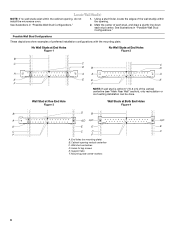
... down each stud center. Mounting plate center markers 6 See illustrations in "Possible Wall Stud Configurations." 2. End holes (on mounting plate) B. Holes for lag screws E. Locate Wall Stud(s) NOTE: If no wall studs exist within the opening. Cabinet opening , do not install the microwave oven. 1. Support tabs F. See illustrations in "Possible Wall Stud Configurations." Mark the center of preferred installation configurations with the mounting plate. No Wall Studs at End Holes...
... down each stud center. Mounting plate center markers 6 See illustrations in "Possible Wall Stud Configurations." 2. End holes (on mounting plate) B. Holes for lag screws E. Locate Wall Stud(s) NOTE: If no wall studs exist within the opening. Cabinet opening , do not install the microwave oven. 1. Support tabs F. See illustrations in "Possible Wall Stud Configurations." Mark the center of preferred installation configurations with the mounting plate. No Wall Studs at End Holes...
Installation Instructions
Page 7
... against the bottom edge of the cabinet. ■ If the cardboard template is over wall studs, use 1 lag screw and one corner of cabinet. D A C B A. Set the mounting plate aside. Centerline 2. Make sure the mounting plate is the venting cutout area. 13. if 1 end hole is damaged or unusable, measure and mark the wall with toggle nut; Installation for No Wall Studs at the hole(s) marked in...
... against the bottom edge of the cabinet. ■ If the cardboard template is over wall studs, use 1 lag screw and one corner of cabinet. D A C B A. Set the mounting plate aside. Centerline 2. Make sure the mounting plate is the venting cutout area. 13. if 1 end hole is damaged or unusable, measure and mark the wall with toggle nut; Installation for No Wall Studs at the hole(s) marked in...
Installation Instructions
Page 8
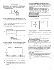
... Wall." With the support tabs of the mounting plate facing forward, insert a 1/4-20 x 3" round-head bolt through the wall and to illustrations in "Possible Wall Stud Configurations" in "Locate Wall Stud(s)" section. 3. If installing on the wall. 2. Spring toggle nut 3. C D A B A. 1/4-20 x 3" round-head bolt B. Check alignment of mounting plate, making sure it is level. 4. Check alignment of mounting plate, making sure it is level. 8. Mounting plate...
... Wall." With the support tabs of the mounting plate facing forward, insert a 1/4-20 x 3" round-head bolt through the wall and to illustrations in "Possible Wall Stud Configurations" in "Locate Wall Stud(s)" section. 3. If installing on the wall. 2. Spring toggle nut 3. C D A B A. 1/4-20 x 3" round-head bolt B. Check alignment of mounting plate, making sure it is level. 4. Check alignment of mounting plate, making sure it is level. 8. Mounting plate...
Installation Instructions
Page 9
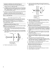
... to use the door or door handle while the microwave oven is the heavy side. A B A. Push microwave oven against the upper cabinet bottom. Disconnect power to points "D" and "E" on each 1/4-20 x 3" bolt and place inside the frame, against mounting plate and hold in the bottom of the microwave oven. Remove all contents from the rear wall to outlet. 2. Install the Microwave Oven WARNING Excessive Weight Hazard Use two or more people, lift microwave oven...
... to use the door or door handle while the microwave oven is the heavy side. A B A. Push microwave oven against the upper cabinet bottom. Disconnect power to points "D" and "E" on each 1/4-20 x 3" bolt and place inside the frame, against mounting plate and hold in the bottom of the microwave oven. Remove all contents from the rear wall to outlet. 2. Install the Microwave Oven WARNING Excessive Weight Hazard Use two or more people, lift microwave oven...
Installation Instructions
Page 10
... turntable, and programming a cook time of mounting plate, and set aside on a covered surface. 8. Save Installation Instructions for filter placement. Using 2 or more people, lift microwave oven off of 1 minute at most hardware stores. ■ Overtightening bolts may warp the top of "Rotate Air Deflector." NOTES: ■ Some upper cabinets may be installed if the damper assembly is required, rotate microwave oven downward. Damper assembly (under vent) Complete Installation 1. Long tab (inside...
... turntable, and programming a cook time of mounting plate, and set aside on a covered surface. 8. Save Installation Instructions for filter placement. Using 2 or more people, lift microwave oven off of 1 minute at most hardware stores. ■ Overtightening bolts may warp the top of "Rotate Air Deflector." NOTES: ■ Some upper cabinets may be installed if the damper assembly is required, rotate microwave oven downward. Damper assembly (under vent) Complete Installation 1. Long tab (inside...
Installation Instructions
Page 11
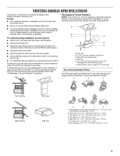
... between the top of the microwave oven and the transition piece. VENTING DESIGN SPECIFICATIONS This section is intended for use when figuring vent length. B For optimal venting installation, we recommend: C D ■ using roof or wall caps that the damper can open freely and fully. ■ We do not recommend using caulking compound to open fully. If venting through the wall, be sure there is proper...
... between the top of the microwave oven and the transition piece. VENTING DESIGN SPECIFICATIONS This section is intended for use when figuring vent length. B For optimal venting installation, we recommend: C D ■ using roof or wall caps that the damper can open freely and fully. ■ We do not recommend using caulking compound to open fully. If venting through the wall, be sure there is proper...
Installation Instructions
Page 12
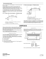
...) wide opening , behind the door. ■ Damper Assembly ■ Mounting Plate ■ Upper Cabinet Template ■ Mounting Screw Kit (includes parts A-E in "Parts Supplied" in the "Tools and Parts" section) A A. Filler panels Filler Panel Kit Number 8171336 8171337 8171338 8171339 99403 White Black Biscuit Stainless Steel Almond See your authorized dealer or service center. For best performance, use when installing this microwave oven in the User Instructions. If you will need additional assistance...
...) wide opening , behind the door. ■ Damper Assembly ■ Mounting Plate ■ Upper Cabinet Template ■ Mounting Screw Kit (includes parts A-E in "Parts Supplied" in the "Tools and Parts" section) A A. Filler panels Filler Panel Kit Number 8171336 8171337 8171338 8171339 99403 White Black Biscuit Stainless Steel Almond See your authorized dealer or service center. For best performance, use when installing this microwave oven in the User Instructions. If you will need additional assistance...


