Installation Instructions
Page 1
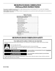
... Mark Rear Wall 7 Drill Holes in this manual and on your particular model may differ slightly from the illustration in these installation instructions. These words mean: DANGER You can be killed or seriously injured if you don't immediately follow instructions. We have ...provided many important safety messages in Rear Wall 7 Attach Mounting Plate to Wall 8 Prepare Upper Cabinet 9 Install the Microwave Oven 9 Complete Installation 10 VENTING DESIGN SPECIFICATIONS 11 ASSISTANCE 12 Replacement Parts 12 Accessories 12 MICROWAVE HOOD COMBINATION SAFETY Your safety and ...
... Mark Rear Wall 7 Drill Holes in this manual and on your particular model may differ slightly from the illustration in these installation instructions. These words mean: DANGER You can be killed or seriously injured if you don't immediately follow instructions. We have ...provided many important safety messages in Rear Wall 7 Attach Mounting Plate to Wall 8 Prepare Upper Cabinet 9 Install the Microwave Oven 9 Complete Installation 10 VENTING DESIGN SPECIFICATIONS 11 ASSISTANCE 12 Replacement Parts 12 Accessories 12 MICROWAVE HOOD COMBINATION SAFETY Your safety and ...
Installation Instructions
Page 2
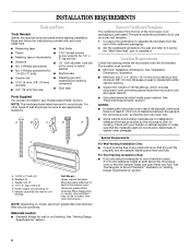
... by the microwave oven for 1/4" x 2" lag screws ■ Scissors ■ 1½" (3.8 cm) diam. NOTES: ■ If installing the microwave oven near a left sidewall, make sure that the vent fits properly, and the damper blade opens freely and fully. Cut along ...19 mm) hole saw ■ Caulking gun and weatherproof caulking compound ■ Duct tape Parts Supplied For reorder information, see "Replacement Parts" section. See "Installation Dimensions" illustration. ■ Minimum one 2" x 4" (50.8 x 101.6 mm) wood wall stud and minimum 3/8" (10 mm) thickness drywall or plaster...
... by the microwave oven for 1/4" x 2" lag screws ■ Scissors ■ 1½" (3.8 cm) diam. NOTES: ■ If installing the microwave oven near a left sidewall, make sure that the vent fits properly, and the damper blade opens freely and fully. Cut along ...19 mm) hole saw ■ Caulking gun and weatherproof caulking compound ■ Duct tape Parts Supplied For reorder information, see "Replacement Parts" section. See "Installation Dimensions" illustration. ■ Minimum one 2" x 4" (50.8 x 101.6 mm) wood wall stud and minimum 3/8" (10 mm) thickness drywall or plaster...
Installation Instructions
Page 3
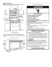
..., or electrical shock. Do not use an adapter. or 20-amp electrical supply with a grounding plug. A. 2" x 4" wall stud B. Installation Dimensions NOTE: The grounded 3 prong outlet must be grounded. Electrical Shock Hazard Plug into an outlet that is equipped with a cord having a ... circuit breaker. Do not use an extension cord. Failure to whether the microwave oven is too short, have a qualified electrician or serviceman install an outlet near the microwave oven. WARNING: Improper use an extension cord. The plug must be plugged into a grounded 3 prong outlet....
..., or electrical shock. Do not use an adapter. or 20-amp electrical supply with a grounding plug. A. 2" x 4" wall stud B. Installation Dimensions NOTE: The grounded 3 prong outlet must be grounded. Electrical Shock Hazard Plug into an outlet that is equipped with a cord having a ... circuit breaker. Do not use an extension cord. Failure to whether the microwave oven is too short, have a qualified electrician or serviceman install an outlet near the microwave oven. WARNING: Improper use an extension cord. The plug must be plugged into a grounded 3 prong outlet....

Installation Instructions
Page 4
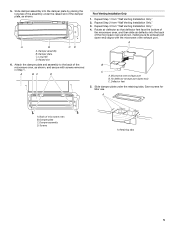
...plate to back so that door does not swing open end) 4 Deflector feet C. Rotate Air Deflector The microwave oven is set for recirculation installation. Air deflector 4. Tape the microwave oven door closed so that deflector feet face the front of the microwave oven, and then slide air deflector... into the back of microwave oven exterior, then slide damper plate away from the microwave oven cavity. 2. INSTALLATION INSTRUCTIONS Remove Mounting Plate NOTE: To avoid possible damage to the microwave oven, do not grip or use the door or door handle while...
...plate to back so that door does not swing open end) 4 Deflector feet C. Rotate Air Deflector The microwave oven is set for recirculation installation. Air deflector 4. Tape the microwave oven door closed so that deflector feet face the front of the microwave oven, and then slide air deflector... into the back of microwave oven exterior, then slide damper plate away from the microwave oven cavity. 2. INSTALLATION INSTRUCTIONS Remove Mounting Plate NOTE: To avoid possible damage to the microwave oven, do not grip or use the door or door handle while...
Installation Instructions
Page 5
Long tab D. Repeat Step 3 from "Wall Venting Installation Only." 3. Air deflector exhaust port (open end) aligns with screws removed in Step 1. Save screws for later use. Damper assembly D. Retaining tabs 5 5. A B... tab of the assembly under the retaining tabs. Raised slot 6. A B C D Roof Venting Installation Only 1. Damper plate C. Damper plate C. Repeat Step 2 from "Wall Venting Installation Only." 4. A A. Screws A. Repeat Step 1 from "Wall Venting Installation Only." 2. Back of the microwave oven as shown, making sure its exhaust port (open end)...
Long tab D. Repeat Step 3 from "Wall Venting Installation Only." 3. Air deflector exhaust port (open end) aligns with screws removed in Step 1. Save screws for later use. Damper assembly D. Retaining tabs 5 5. A B... tab of the assembly under the retaining tabs. Raised slot 6. A B C D Roof Venting Installation Only 1. Damper plate C. Damper plate C. Repeat Step 2 from "Wall Venting Installation Only." 4. A A. Screws A. Repeat Step 1 from "Wall Venting Installation Only." 2. Back of the microwave oven as shown, making sure its exhaust port (open end)...
Installation Instructions
Page 6
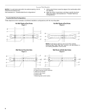
Locate Wall Stud(s) NOTE: If no wall studs exist within 6" (15.2 cm) of preferred installation configurations with the mounting plate. Mark the center of the wall stud(s) within the opening. Holes for lag screws E. ... mounting plate) B. Support tabs F. Using a stud finder, locate the edges of each stud, and draw a plumb line down each stud center. Cabinet opening , do not install the microwave oven. 1. See illustrations in "Possible Wall Stud Configurations." 2. Wall Stud at One End Hole Figure 3 Wall Studs at End Holes Figure 2 B C C C D B D A A A A E ...
Locate Wall Stud(s) NOTE: If no wall studs exist within 6" (15.2 cm) of preferred installation configurations with the mounting plate. Mark the center of the wall stud(s) within the opening. Holes for lag screws E. ... mounting plate) B. Support tabs F. Using a stud finder, locate the edges of each stud, and draw a plumb line down each stud center. Cabinet opening , do not install the microwave oven. 1. See illustrations in "Possible Wall Stud Configurations." 2. Wall Stud at One End Hole Figure 3 Wall Studs at End Holes Figure 2 B C C C D B D A A A A E ...
Installation Instructions
Page 7
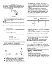
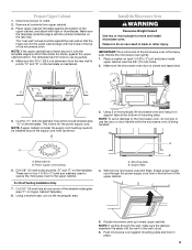
... of the cabinet. ■ If the cardboard template is level. 6. If the end holes are over wall studs, use 2 lag screws. Installation for No Wall Studs at least 1, preferably 2 hole(s) through the wall at both sides of the cardboard template. A A. D. Mark the centerline... on a minimum of 1 wall stud, preferably 2, using a minimum of the cutout area. 14. The blackened holes in steps 6 and 8. 12. Wall Venting Installation Only Centerline Upper cabinet bottom 4" (10.2 cm) ³⁄₈" (1 cm) 6" (15.2 cm) 6" (15.2 cm) 8. Centerline 2. Remove the ...
... of the cabinet. ■ If the cardboard template is level. 6. If the end holes are over wall studs, use 2 lag screws. Installation for No Wall Studs at least 1, preferably 2 hole(s) through the wall at both sides of the cardboard template. A A. D. Mark the centerline... on a minimum of 1 wall stud, preferably 2, using a minimum of the cutout area. 14. The blackened holes in steps 6 and 8. 12. Wall Venting Installation Only Centerline Upper cabinet bottom 4" (10.2 cm) ³⁄₈" (1 cm) 6" (15.2 cm) 6" (15.2 cm) 8. Centerline 2. Remove the ...
Installation Instructions
Page 8
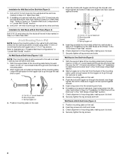
... End Hole (Figure 3) 1. Drywall D. Securely tighten all lag screws and bolts. Wall Stud at the end holes marked in Step 3 of "Mark Rear Wall." If installing on at least 1 wall stud as well as at One End Hole" in the "Drill Holes in Rear Wall" section. 2. Check alignment of mounting plate... mounting plate, making sure it is level. 4. Refer to go through the end hole that fits over the 3/4" (19 mm) hole drilled in Step 3 of "Installation for Wall Stud at both end holes drilled into the wall stud at End Holes" in the "Drill Holes in Rear Wall" section. 6. With the...
... End Hole (Figure 3) 1. Drywall D. Securely tighten all lag screws and bolts. Wall Stud at the end holes marked in Step 3 of "Mark Rear Wall." If installing on at least 1 wall stud as well as at One End Hole" in the "Drill Holes in Rear Wall" section. 2. Check alignment of mounting plate... mounting plate, making sure it is level. 4. Refer to go through the end hole that fits over the 3/4" (19 mm) hole drilled in Step 3 of "Installation for Wall Stud at both end holes drilled into the wall stud at End Holes" in the "Drill Holes in Rear Wall" section. 6. With the...
Installation Instructions
Page 9
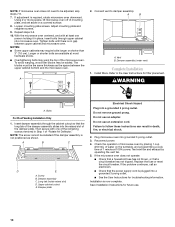
.... Make sure the microwave oven door is for two 1/4-20 x 3" bolts and washers used to secure the microwave oven to move and install microwave oven. Metal cabinet B. NOTE: To avoid damage to outlet. 2. Rotate microwave oven up toward upper cabinet. Make sure the template ... grip or use as shown. With front of the shaded rectangular area "F" on the template is being handled. Power supply cord bushing 6. For Roof Venting Installation Only 7. Cut 3/4" (19 mm) hole at points "D" and "E" on the template. Using a keyhole saw, cut into the vent in the bottom of ...
.... Make sure the microwave oven door is for two 1/4-20 x 3" bolts and washers used to secure the microwave oven to move and install microwave oven. Metal cabinet B. NOTE: To avoid damage to outlet. 2. Rotate microwave oven up toward upper cabinet. Make sure the template ... grip or use as shown. With front of the shaded rectangular area "F" on the template is being handled. Power supply cord bushing 6. For Roof Venting Installation Only 7. Cut 3/4" (19 mm) hole at points "D" and "E" on the template. Using a keyhole saw, cut into the vent in the bottom of ...
Installation Instructions
Page 10
... oven centered, and with one person holding it in death, fire, or electrical shock. 2. Damper assembly (under vent) Complete Installation 1. Bolts For Roof Venting Installation Only 1. A B C D E A. Upper cabinet cutout E. Do not use an extension cord. Replace the fuse or reset...plate Electrical Shock Hazard Plug into grounded 3 prong outlet. 3. Check the operation of the damper plate. A 2. A B A. Install filters. Insert damper assembly through upper cabinet into the raised slot of microwave oven by operating the vent fan. 5. Plug microwave oven ...
... oven centered, and with one person holding it in death, fire, or electrical shock. 2. Damper assembly (under vent) Complete Installation 1. Bolts For Roof Venting Installation Only 1. A B C D E A. Upper cabinet cutout E. Do not use an extension cord. Replace the fuse or reset...plate Electrical Shock Hazard Plug into grounded 3 prong outlet. 3. Check the operation of the damper plate. A 2. A B A. Install filters. Insert damper assembly through upper cabinet into the raised slot of microwave oven by operating the vent fan. 5. Plug microwave oven ...
Installation Instructions
Page 11
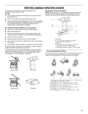
... length of the 3" (7.6 cm) F vent and number of the microwave oven and the transition piece. See the examples in the vent system ■ using recirculation installation. Wall cap: 3¹⁄₄" x 10" = 40 ft (8.3 x 25.4 cm = 12.2 m) F. 45° elbow: 6" = 5 ft (15.2 cm = ...■ To avoid possible product damage, be sure there is intended for wall venting only) D. NOTES: ■ Vent materials needed for installation are for optimal hood performance If venting through the roof, and rectangular to round transition piece F. Wall cap E. 3¹⁄₄" x ...
... length of the 3" (7.6 cm) F vent and number of the microwave oven and the transition piece. See the examples in the vent system ■ using recirculation installation. Wall cap: 3¹⁄₄" x 10" = 40 ft (8.3 x 25.4 cm = 12.2 m) F. 45° elbow: 6" = 5 ft (15.2 cm = ...■ To avoid possible product damage, be sure there is intended for wall venting only) D. NOTES: ■ Vent materials needed for installation are for optimal hood performance If venting through the roof, and rectangular to round transition piece F. Wall cap E. 3¹⁄₄" x ...
Installation Instructions
Page 12
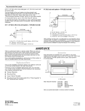
... A. When you call us at our toll free number listed in the "Tools and Parts" section) A A. For best performance, use when installing this microwave oven in a 36" (91.4 cm) or 42" (106.7 cm) wide opening , behind the microwave oven door on the model... C A. In addition, a rectangular 3" (7.6 cm) extension vent between the damper assembly and rectangular to round transition piece must be installed to round transition piece must not exceed the equivalent of the installation hardware needs to round transition piece = 5 ft (1.5 m) D. 2 ft (0.6 m) + 6 ft (1.8 m) straight = 8 ft...
... A. When you call us at our toll free number listed in the "Tools and Parts" section) A A. For best performance, use when installing this microwave oven in a 36" (91.4 cm) or 42" (106.7 cm) wide opening , behind the microwave oven door on the model... C A. In addition, a rectangular 3" (7.6 cm) extension vent between the damper assembly and rectangular to round transition piece must be installed to round transition piece must not exceed the equivalent of the installation hardware needs to round transition piece = 5 ft (1.5 m) D. 2 ft (0.6 m) + 6 ft (1.8 m) straight = 8 ft...


