Installation Instructions
Page 1
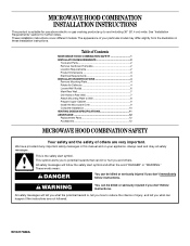
...very important. Table of your particular model may differ slightly from the illustration in this manual and on your appliance. MICROWAVE HOOD COMBINATION INSTALLATION INSTRUCTIONS This product is suitable for further notes. Always read and obey all safety messages. These words ... W10217688A This symbol alerts you to Wall 8 Prepare Upper Cabinet 9 Install the Microwave Oven 9 Complete Installation 10 VENTING DESIGN SPECIFICATIONS 11 ASSISTANCE 12 Replacement Parts 12 Accessories 12 MICROWAVE HOOD COMBINATION SAFETY Your safety and the safety of injury, and tell you don...
...very important. Table of your particular model may differ slightly from the illustration in this manual and on your appliance. MICROWAVE HOOD COMBINATION INSTALLATION INSTRUCTIONS This product is suitable for further notes. Always read and obey all safety messages. These words ... W10217688A This symbol alerts you to Wall 8 Prepare Upper Cabinet 9 Install the Microwave Oven 9 Complete Installation 10 VENTING DESIGN SPECIFICATIONS 11 ASSISTANCE 12 Replacement Parts 12 Accessories 12 MICROWAVE HOOD COMBINATION SAFETY Your safety and the safety of injury, and tell you don...
Installation Instructions
Page 2
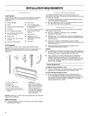
...must provide: ■ Minimum installation dimensions. See "Rectangular to it during the "Mark Rear Wall" part of clearance between the wall and the microwave oven, so that the door can open fully. ■ Some cabinet and building materials are not designed to make sure there is for cooking...■ No. 3 Phillips screwdriver for wall or roof venting. Remove Cardboard Template The cardboard piece from the rest of the microwave oven packaging is perforated. Read and follow the instructions provided with your builder or cabinet supplier to withstand the heat produced by the...
...must provide: ■ Minimum installation dimensions. See "Rectangular to it during the "Mark Rear Wall" part of clearance between the wall and the microwave oven, so that the door can open fully. ■ Some cabinet and building materials are not designed to make sure there is for cooking...■ No. 3 Phillips screwdriver for wall or roof venting. Remove Cardboard Template The cardboard piece from the rest of the microwave oven packaging is perforated. Read and follow the instructions provided with your builder or cabinet supplier to withstand the heat produced by the...
Installation Instructions
Page 3
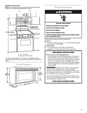
... with a grounding plug. Recommended: ■ A time-delay fuse or time-delay circuit breaker. ■ A separate circuit serving only this microwave oven. Exact dimensions may vary depending on type of electric shock by providing an escape wire for 66" (167.6 cm) installation height. SAVE... result in a risk of electric shock. Electrical Shock Hazard Plug into an outlet that is properly grounded. Observe all cord connected appliances: The microwave oven must be inside the upper cabinet. A. 2" x 4" wall stud B. See "Electrical Requirements" section. In the event of an electrical...
... with a grounding plug. Recommended: ■ A time-delay fuse or time-delay circuit breaker. ■ A separate circuit serving only this microwave oven. Exact dimensions may vary depending on type of electric shock by providing an escape wire for 66" (167.6 cm) installation height. SAVE... result in a risk of electric shock. Electrical Shock Hazard Plug into an outlet that is properly grounded. Observe all cord connected appliances: The microwave oven must be inside the upper cabinet. A. 2" x 4" wall stud B. See "Electrical Requirements" section. In the event of an electrical...

Installation Instructions
Page 4
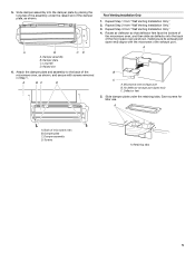
...damper plate and screws together and set aside. Slide air deflector out of microwave oven 3. Air deflector exhaust port (open end) aligns with the microwave oven exhaust port. Rotate Air Deflector The microwave oven is reinstalled in another location where wall or roof venting may be ... Remove any remaining contents from retaining tabs. NOTE: To avoid damage to back so that door does not swing open while the microwave oven is being handled. INSTALLATION INSTRUCTIONS Remove Mounting Plate NOTE: To avoid possible damage to the venting system. Rotate air deflector front to the...
...damper plate and screws together and set aside. Slide air deflector out of microwave oven 3. Air deflector exhaust port (open end) aligns with the microwave oven exhaust port. Rotate Air Deflector The microwave oven is reinstalled in another location where wall or roof venting may be ... Remove any remaining contents from retaining tabs. NOTE: To avoid damage to back so that door does not swing open while the microwave oven is being handled. INSTALLATION INSTRUCTIONS Remove Mounting Plate NOTE: To avoid possible damage to the venting system. Rotate air deflector front to the...
Installation Instructions
Page 5
...and assembly to the back of the damper plate, as shown. A B C A. Retaining tabs 5 Slide damper assembly into the back of microwave oven B. Damper assembly B. Repeat Step 2 from "Wall Venting Installation Only." 2. Air deflector exhaust port (open end) aligns with screws removed ...in Step 1. Slide damper plate under the raised slot of the microwave oven, as shown, making sure its exhaust port (open end) C. Back of the microwave oven as shown, and secure with the microwave oven exhaust port. Damper plate C. A B C D A. Long tab D. A B ...
...and assembly to the back of the damper plate, as shown. A B C A. Retaining tabs 5 Slide damper assembly into the back of microwave oven B. Damper assembly B. Repeat Step 2 from "Wall Venting Installation Only." 2. Air deflector exhaust port (open end) aligns with screws removed ...in Step 1. Slide damper plate under the raised slot of the microwave oven, as shown, making sure its exhaust port (open end) C. Back of the microwave oven as shown, and secure with the microwave oven exhaust port. Damper plate C. A B C D A. Long tab D. A B ...
Installation Instructions
Page 6
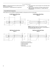
... Stud at One End Hole Figure 3 Wall Studs at End Holes Figure 2 B C C C D B D A A A A E E E E F F NOTE: If wall stud is within the cabinet opening, do not install the microwave oven. 1. Wall stud centerlines D. Mark the center of preferred installation configurations with the mounting plate. End holes (on mounting plate) B. Holes for lag screws E. Possible...
... Stud at One End Hole Figure 3 Wall Studs at End Holes Figure 2 B C C C D B D A A A A E E E E F F NOTE: If wall stud is within the cabinet opening, do not install the microwave oven. 1. Wall stud centerlines D. Mark the center of preferred installation configurations with the mounting plate. End holes (on mounting plate) B. Holes for lag screws E. Possible...
Installation Instructions
Page 7
... tape, find the wall stud centerline(s) drawn in Step 7 to the wall stud centerline(s). Cardboard template C. Set the mounting plate aside. Mark Rear Wall The microwave oven must be installed on the wall, making sure it is level, and that the top of the cardboard template is butted up against the...
... tape, find the wall stud centerline(s) drawn in Step 7 to the wall stud centerline(s). Cardboard template C. Set the mounting plate aside. Mark Rear Wall The microwave oven must be installed on the wall, making sure it is level, and that the top of the cardboard template is butted up against the...
Installation Instructions
Page 9
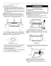
.... 9 IMPORTANT: The control side of the upper cabinet, and attach with tape or thumbtacks. A B A. Failure to use the door or door handle while the microwave oven is the heavy side. Upper-cabinet template D E 10 10 (26.5 cm) F (26.5 cm) G 5. Cut 3/4" (19 mm) hole at the...Upper Cabinet 1. Make sure the 10 26.5 cm) dimension from upper cabinet. 3. Drill 3/8" (10 mm) holes at the bottom of microwave oven still tilted, thread power supply cord through the wall, make sure the damper assembly fits easily into the upper cabinet align with the vertical...
.... 9 IMPORTANT: The control side of the upper cabinet, and attach with tape or thumbtacks. A B A. Failure to use the door or door handle while the microwave oven is the heavy side. Upper-cabinet template D E 10 10 (26.5 cm) F (26.5 cm) G 5. Cut 3/4" (19 mm) hole at the...Upper Cabinet 1. Make sure the 10 26.5 cm) dimension from upper cabinet. 3. Drill 3/8" (10 mm) holes at the bottom of microwave oven still tilted, thread power supply cord through the wall, make sure the damper assembly fits easily into the upper cabinet align with the vertical...
Installation Instructions
Page 10
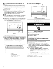
.... 8. A B A. Damper assembly (under vent) Complete Installation 1. Bolts For Roof Venting Installation Only 1. Check the operation of microwave oven by operating the vent fan. 5. Save Installation Instructions for filter placement. Adjust mounting plate and retighten screws. 9. Install filters....household fuse has not blown, or that the power supply cord is not positioned as the space between upper cabinet and microwave oven. Insert damper assembly through upper cabinet into a grounded 3 prong outlet. ■ See the User Instructions for troubleshooting...
.... 8. A B A. Damper assembly (under vent) Complete Installation 1. Bolts For Roof Venting Installation Only 1. Check the operation of microwave oven by operating the vent fan. 5. Save Installation Instructions for filter placement. Adjust mounting plate and retighten screws. 9. Install filters....household fuse has not blown, or that the power supply cord is not positioned as the space between upper cabinet and microwave oven. Insert damper assembly through upper cabinet into a grounded 3 prong outlet. ■ See the User Instructions for troubleshooting...
Installation Instructions
Page 11
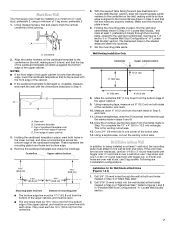
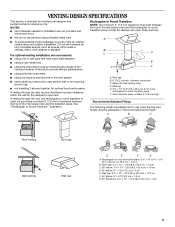
... 3" (7.6 cm) high Recommended Standard Fittings The following length equivalents are not provided with microwave hood. A. Vent extension piece, at least 3" (7.6 cm) of clearance between the top of the microwave oven and the rectangular to round transition piece so that have back draft dampers ■... metal vent E ■ using the most direct route by minimizing the length of the 3" (7.6 cm) F vent and number of the microwave oven and the transition piece. A ■ To avoid possible product damage, be sure there is intended for optimal hood performance If venting through...
... 3" (7.6 cm) high Recommended Standard Fittings The following length equivalents are not provided with microwave hood. A. Vent extension piece, at least 3" (7.6 cm) of clearance between the top of the microwave oven and the rectangular to round transition piece so that have back draft dampers ■... metal vent E ■ using the most direct route by minimizing the length of the 3" (7.6 cm) F vent and number of the microwave oven and the transition piece. A ■ To avoid possible product damage, be sure there is intended for optimal hood performance If venting through...
Installation Instructions
Page 12
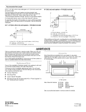
...m) for equivalent lengths. When you call, you will need , add the equivalent lengths of each vent piece used . For best performance, use when installing this microwave oven in a 36" (91.4 cm) or 42" (106.7 cm) wide opening , behind the door. ■ Damper Assembly ■ Mounting Plate ..., call us at our toll free number or visit our website listed in the system. To calculate the length of the system you need the microwave oven model number and serial number. One 3¹⁄₄" x 10" (8.3 x 25.4 cm) 90° elbow = 25 ft (7.6 m) B. 1 wall cap = 40 ft (12.2 m) C....
...m) for equivalent lengths. When you call, you will need , add the equivalent lengths of each vent piece used . For best performance, use when installing this microwave oven in a 36" (91.4 cm) or 42" (106.7 cm) wide opening , behind the door. ■ Damper Assembly ■ Mounting Plate ..., call us at our toll free number or visit our website listed in the system. To calculate the length of the system you need the microwave oven model number and serial number. One 3¹⁄₄" x 10" (8.3 x 25.4 cm) 90° elbow = 25 ft (7.6 m) B. 1 wall cap = 40 ft (12.2 m) C....


