
Specification Sheet
Page 1
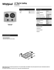
... in the U.S.A. 21" Electric Cooktop RCS2012R Electrical Details Amps 20 Volts 240 Stainless Steel RCS2012RS Key Features & Benefits Chrome Drip Bowls Helps catch spills and wipe up easily. Specifications subject to change without notice. ®/™ © 2020. D200104XXE. RCS2012RSpecSheetV01. Technical Details Fuel Type Number of Burners/ Elements Burner/Element Power Burner/Element Type/Size Dimensions Product Dimensions (H x W x D) Cutout Dimensions (W x D) Reference Material Dimension Guide Install Guide Use & Care Guide Warranty Electric 2 (1) 1250W/900W (1) 2100W...
... in the U.S.A. 21" Electric Cooktop RCS2012R Electrical Details Amps 20 Volts 240 Stainless Steel RCS2012RS Key Features & Benefits Chrome Drip Bowls Helps catch spills and wipe up easily. Specifications subject to change without notice. ®/™ © 2020. D200104XXE. RCS2012RSpecSheetV01. Technical Details Fuel Type Number of Burners/ Elements Burner/Element Power Burner/Element Type/Size Dimensions Product Dimensions (H x W x D) Cutout Dimensions (W x D) Reference Material Dimension Guide Install Guide Use & Care Guide Warranty Electric 2 (1) 1250W/900W (1) 2100W...
Installation Instructions
Page 2
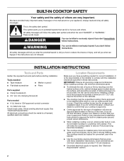
... connector ■■ UL listed wire nuts Check local codes. INSTALLATION INSTRUCTIONS Tools and Parts Gather the required tools and parts before starting installation. See "Electrical Requirements." IMPORTANT: Observe all safety messages. Check the cooktop burner box for this manual and on the top of the cabinets. ■■ The cooktop must be a specified cooktop that is to oven manufacturer's Installation Instructions for approval for correct installation. When installing cooktop, use minimum dimensions given. ■■ To...
... connector ■■ UL listed wire nuts Check local codes. INSTALLATION INSTRUCTIONS Tools and Parts Gather the required tools and parts before starting installation. See "Electrical Requirements." IMPORTANT: Observe all safety messages. Check the cooktop burner box for this manual and on the top of the cabinets. ■■ The cooktop must be a specified cooktop that is to oven manufacturer's Installation Instructions for approval for correct installation. When installing cooktop, use minimum dimensions given. ■■ To...
Installation Instructions
Page 3
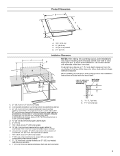
...) minimum clearance from the countertop to cooktop H. When installing a hood above this modification, use a base cabinet with the hood itself. To avoid this cooktop, follow the installation instructions included with sidewalls wider than No. 28 MSG sheet steel, 0.015" [0.04 cm] stainless steel or 0.024" [0.06 cm] aluminum or 0.020" [0.05 cm] copper) D. 13" (33 cm) recommended upper cabinet depth E. 3" (7.6 cm) F. 151/2" (34.4 cm) on 21" (53.3 cm) models B. counter illustration...
...) minimum clearance from the countertop to cooktop H. When installing a hood above this modification, use a base cabinet with the hood itself. To avoid this cooktop, follow the installation instructions included with sidewalls wider than No. 28 MSG sheet steel, 0.015" [0.04 cm] stainless steel or 0.024" [0.06 cm] aluminum or 0.020" [0.05 cm] copper) D. 13" (33 cm) recommended upper cabinet depth E. 3" (7.6 cm) F. 151/2" (34.4 cm) on 21" (53.3 cm) models B. counter illustration...

Installation Instructions
Page 4
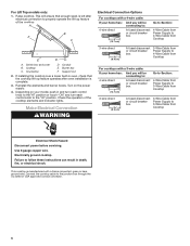
... fuse box or circuit breaker box should be moved if servicing becomes necessary in death, fire, or electrical shock. Use 8 gauge copper wire. Electrical Requirements WARNING Install Cooktop WARNING Excessive Weight Hazard Use two or more people, place the cooktop upside down on a protective surface. Burner box bottom D. Electrical Shock Hazard Disconnect power before or after is required on a separate, 40 A circuit, fused on both sides of the line. ■■ The cooktop should be connected directly...
... fuse box or circuit breaker box should be moved if servicing becomes necessary in death, fire, or electrical shock. Use 8 gauge copper wire. Electrical Requirements WARNING Install Cooktop WARNING Excessive Weight Hazard Use two or more people, place the cooktop upside down on a protective surface. Burner box bottom D. Electrical Shock Hazard Disconnect power before or after is required on a separate, 40 A circuit, fused on both sides of the line. ■■ The cooktop should be connected directly...
Installation Instructions
Page 5
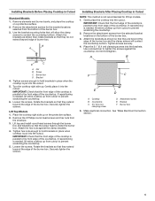
... countertop. Remove the attachment screws for lift top models. 1. Use the bracket mounting holes that they do not extend beyond the edge of the countertop. Place the 21⁄2" (6.4 cm) clamping screws into the cutout. Tighten screws enough to prevent scratching the countertop. 5. Lift Top Models 1. Rotate the brackets so that will contact the countertop bottom. See "Make Electrical Connection section." 5 Burner box D. If repositioning is needed...
... countertop. Remove the attachment screws for lift top models. 1. Use the bracket mounting holes that they do not extend beyond the edge of the countertop. Place the 21⁄2" (6.4 cm) clamping screws into the cutout. Tighten screws enough to prevent scratching the countertop. 5. Lift Top Models 1. Rotate the brackets so that will contact the countertop bottom. See "Make Electrical Connection section." 5 Burner box D. If repositioning is needed...
Installation Instructions
Page 6
... the operation of the cooktop. If installing the cooktop over a lower built-in oven, check that enough slack is left after oven installlation is manufactured with a 3-wire cable: If your model, push in death, fire, or electrical shock. Depending on the power supply. 4. Reinstall the elements and burner bowls. Support rod 2. Failure to follow these instructions can result in and turn each control knob to the"HI...
... the operation of the cooktop. If installing the cooktop over a lower built-in oven, check that enough slack is left after oven installlation is manufactured with a 3-wire cable: If your model, push in death, fire, or electrical shock. Depending on the power supply. 4. Reinstall the elements and burner bowls. Support rod 2. Failure to follow these instructions can result in and turn each control knob to the"HI...

Installation Instructions
Page 7
... listed wire nuts. 7. Install junction box cover. 9. Reconnect power. If there is an extra part, go back through the steps to remove waxy residue caused by protective shipping material. Remove junction box cover, if present. 3. Connect the two black wires together using the UL listed wire nuts. 6. Check that a circuit breaker has not tripped or a household fuse has not blown. Connect the flexible cable conduit from the cooktop to the neutral (white) junction box wire...
... listed wire nuts. 7. Install junction box cover. 9. Reconnect power. If there is an extra part, go back through the steps to remove waxy residue caused by protective shipping material. Remove junction box cover, if present. 3. Connect the two black wires together using the UL listed wire nuts. 6. Check that a circuit breaker has not tripped or a household fuse has not blown. Connect the flexible cable conduit from the cooktop to the neutral (white) junction box wire...
Dimension Guide
Page 1
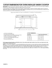
... the 2 holes. 8304571A Center the cooktop cutout over an oven. Allow 1.6 cm) for cutout dimensions. See Cutout Dimensions chart. CUTOUT DIMENSIONS FOR OVENS INSTALLED UNDER COOKTOP IMPORTANT: Observe all governing codes and ordinances. E. 27¾" (70.5 cm) minimum cutout height F. 36" (91.4 cm) from cabinet base to the junction box. On models with the maximum allowable wood cabinet temperatures of the side wall surface to pass the appliance cable through to drill...
... the 2 holes. 8304571A Center the cooktop cutout over an oven. Allow 1.6 cm) for cutout dimensions. See Cutout Dimensions chart. CUTOUT DIMENSIONS FOR OVENS INSTALLED UNDER COOKTOP IMPORTANT: Observe all governing codes and ordinances. E. 27¾" (70.5 cm) minimum cutout height F. 36" (91.4 cm) from cabinet base to the junction box. On models with the maximum allowable wood cabinet temperatures of the side wall surface to pass the appliance cable through to drill...
Dimension Guide
Page 2
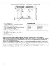
... 2" (5.1 cm) is recommended that the junction box for oven to the undercounter label located on top of countertop. F. 27¾" (70.5 cm) minimum cutout height G. H. 36" (91.4 cm) from the top of junction box to bottom of the oven chassis. Approved Built-In Oven and Gas Cooktop Combinations A B C D E D E F G H I J M L K N A. 24" (61 cm) cabinet depth B. 1" (2.5 cm) clearance from cabinet base to countertop I. CUTOUT DIMENSIONS Oven Size 24" (61 cm) 27" (68.6 cm) 30...
... 2" (5.1 cm) is recommended that the junction box for oven to the undercounter label located on top of countertop. F. 27¾" (70.5 cm) minimum cutout height G. H. 36" (91.4 cm) from the top of junction box to bottom of the oven chassis. Approved Built-In Oven and Gas Cooktop Combinations A B C D E D E F G H I J M L K N A. 24" (61 cm) cabinet depth B. 1" (2.5 cm) clearance from cabinet base to countertop I. CUTOUT DIMENSIONS Oven Size 24" (61 cm) 27" (68.6 cm) 30...

