Installation Guide
Page 2
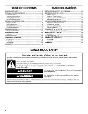
... follow the safety alert symbol and either the word "DANGER" or "WARNING." TABLE OF CONTENTS RANGE HOOD SAFETY 2 INSTALLATION REQUIREMENTS 4 Tools and Parts 4 Location Requirements 4 Venting Requirements 5 Electrical Requirements 6 INSTALLATION INSTRUCTIONS 7 Prepare Location 7 Install Range Hood 8 Make Electrical Connection 9 Complete Installation 10 RANGE HOOD USE 10 Range Hood Controls 10 RANGE HOOD CARE 11 Cleaning 11 WIRING DIAGRAM 12 ASSISTANCE OR SERVICE 13 In the U.S.A 13 In Canada 13 Accessories 13 WARRANTY 14 TABLE DES MATIÈRES SÉCURITÉ DE LA...
... follow the safety alert symbol and either the word "DANGER" or "WARNING." TABLE OF CONTENTS RANGE HOOD SAFETY 2 INSTALLATION REQUIREMENTS 4 Tools and Parts 4 Location Requirements 4 Venting Requirements 5 Electrical Requirements 6 INSTALLATION INSTRUCTIONS 7 Prepare Location 7 Install Range Hood 8 Make Electrical Connection 9 Complete Installation 10 RANGE HOOD USE 10 Range Hood Controls 10 RANGE HOOD CARE 11 Cleaning 11 WIRING DIAGRAM 12 ASSISTANCE OR SERVICE 13 In the U.S.A 13 In Canada 13 Accessories 13 WARRANTY 14 TABLE DES MATIÈRES SÉCURITÉ DE LA...
Installation Guide
Page 3
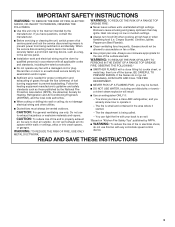
... questions, contact the manufacturer. ■ Before servicing or cleaning the unit, switch power off the burner. You can fight the fire with a close fitting lid, cookie sheet, or metal tray, then turn hood ON when cooking at high settings. CAUTION: For general ventilating use to an exit. Heat oils slowly on fan or filter. ■ Use proper pan size. Always use this unit only in the manner intended by...
... questions, contact the manufacturer. ■ Before servicing or cleaning the unit, switch power off the burner. You can fight the fire with a close fitting lid, cookie sheet, or metal tray, then turn hood ON when cooking at high settings. CAUTION: For general ventilating use to an exit. Heat oils slowly on fan or filter. ■ Use proper pan size. Always use this unit only in the manner intended by...

Installation Guide
Page 4
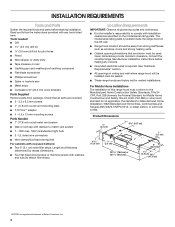
... Remove parts from strong draft areas, such as required For cabinets with washers and nuts (to comply with installation clearances specified on the left wall. ■ Range hood location should be sealed. ■ These range hoods are included. ■ 2 - 3.5 x 9.5 mm screws ■ 7" (17.8 cm) round vent mounting plate ■ T-10 Torx®† adapter ■ 4 - 4.5 x 13 mm mounting screws Parts Needed ■ 7" (17.8 cm) round metal vent system ■ Wall or roof cap with local codes. The model/serial rating plate...
... Remove parts from strong draft areas, such as required For cabinets with washers and nuts (to comply with installation clearances specified on the left wall. ■ Range hood location should be sealed. ■ These range hoods are included. ■ 2 - 3.5 x 9.5 mm screws ■ 7" (17.8 cm) round vent mounting plate ■ T-10 Torx®† adapter ■ 4 - 4.5 x 13 mm mounting screws Parts Needed ■ 7" (17.8 cm) round metal vent system ■ Wall or roof cap with local codes. The model/serial rating plate...

Installation Guide
Page 5
.... ■ Do not use of makeup air systems when using ventilation systems greater than 1 elbow is a minimum of 24" (61 cm) of air movement. Consult your HVAC professional for 30" (76.2 cm) models and 36" (91.4 cm) min. Roof Venting Wall Venting B A A B C C A. 7" (17.8 cm) round vent through the roof or wall. to cooking surface C. 30" (76.2 cm) min. cabinet width for vent system. Wall cap with a maximum length of range hood to 24" (61...
.... ■ Do not use of makeup air systems when using ventilation systems greater than 1 elbow is a minimum of 24" (61 cm) of air movement. Consult your HVAC professional for 30" (76.2 cm) models and 36" (91.4 cm) min. Roof Venting Wall Venting B A A B C C A. 7" (17.8 cm) round vent through the roof or wall. to cooking surface C. 30" (76.2 cm) min. cabinet width for vent system. Wall cap with a maximum length of range hood to 24" (61...

Installation Guide
Page 6
..., 60 Hz., AC only, 15-amp, fused electrical circuit is adequate. If codes permit and a separate ground wire is used in conformance with the rating of the appliance as specified on the rear wall of copper wire using special connectors and/or tools designed and UL listed for each vent piece used , it is recommended that a qualified electrician determine that the electrical installation is located behind the filter on the model/serial rating plate.
..., 60 Hz., AC only, 15-amp, fused electrical circuit is adequate. If codes permit and a separate ground wire is used in conformance with the rating of the appliance as specified on the rear wall of copper wire using special connectors and/or tools designed and UL listed for each vent piece used , it is recommended that a qualified electrician determine that the electrical installation is located behind the filter on the model/serial rating plate.

Installation Guide
Page 7
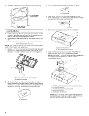
...) for exhaust vent. 1. Lift the range hood and set it upside down onto covered surface. 5. Install screws to attach filler strips in the area the vent opening will be installed before hood is proper clearance within the ceiling or wall for 36" (91.4 cm) models Cabinet bottom 3" (7.6 cm) Wall To wire through the rear wall at this line that is 2.2 cm) from back wall. Before making cutouts, make a circular vent openings on your model, determine which venting method...
...) for exhaust vent. 1. Lift the range hood and set it upside down onto covered surface. 5. Install screws to attach filler strips in the area the vent opening will be installed before hood is proper clearance within the ceiling or wall for 36" (91.4 cm) models Cabinet bottom 3" (7.6 cm) Wall To wire through the rear wall at this line that is 2.2 cm) from back wall. Before making cutouts, make a circular vent openings on your model, determine which venting method...
Installation Guide
Page 8
...by centering beneath cabinet. cabinet cutouts A A. Set range hood aside on ordering, see "Accessories" section) B. 3.5 x 9.5 mm screws C. 7" (17.8 cm) round vent mounting plate D. Install the 4 - 4.5 mm x 13 mm mounting screws in upper cabinet or wall. See "Venting Requirements" section. 2. Round vent knockout B. A A. Round vent knockout E. Drill pilot hole 4. Use ¹⁄₈" (3 mm) drill bit and drill 4 pilot holes as an accessory. Install 7" (17.8 cm) round vent mounting plate. Attach to seal exterior wall or roof opening . 3. A ¹...
...by centering beneath cabinet. cabinet cutouts A A. Set range hood aside on ordering, see "Accessories" section) B. 3.5 x 9.5 mm screws C. 7" (17.8 cm) round vent mounting plate D. Install the 4 - 4.5 mm x 13 mm mounting screws in upper cabinet or wall. See "Venting Requirements" section. 2. Round vent knockout B. A A. Round vent knockout E. Drill pilot hole 4. Use ¹⁄₈" (3 mm) drill bit and drill 4 pilot holes as an accessory. Install 7" (17.8 cm) round vent mounting plate. Attach to seal exterior wall or roof opening . 3. A ¹...

Installation Guide
Page 9
... final position. Reconnect power. 9 NOTE: Do not reconnect power until the installation is complete. 2. Use UL listed wire connectors and connect black wires (B) together. Failure to green ground screw in the "Make Electrical Connection" section. Then push the hood toward the wall so that back draft dampers work properly. Terminal box cover B. Replace all parts and panels before servicing. Connect green (or bare) ground wire from the terminal box cover. Power Supply Cable Installation 1. For direct wire installations, run the home power supply cable according to...
... final position. Reconnect power. 9 NOTE: Do not reconnect power until the installation is complete. 2. Use UL listed wire connectors and connect black wires (B) together. Failure to green ground screw in the "Make Electrical Connection" section. Then push the hood toward the wall so that back draft dampers work properly. Terminal box cover B. Replace all parts and panels before servicing. Connect green (or bare) ground wire from the terminal box cover. Power Supply Cable Installation 1. For direct wire installations, run the home power supply cable according to...
Installation Guide
Page 10
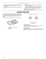
See "Range Hood Use" section. Disconnect power and check wiring connections. NOTE: To get the most efficient use from the cooktop area. On/Off light switch B. Replace grease filter if removed. RANGE HOOD USE The range hood is complete to the right for Off. 10 See "Replacing the Incandescent Light Bulb" in the "Range Hood Care" section. 2. Check the operation of the range hood. The hood controls are located on the top of the range hood fan and light. Filter retainer C. Grease filter A B A. Push the fan switch to clear all...
See "Range Hood Use" section. Disconnect power and check wiring connections. NOTE: To get the most efficient use from the cooktop area. On/Off light switch B. Replace grease filter if removed. RANGE HOOD USE The range hood is complete to the right for Off. 10 See "Replacing the Incandescent Light Bulb" in the "Range Hood Care" section. 2. Check the operation of the range hood. The hood controls are located on the top of the range hood fan and light. Filter retainer C. Grease filter A B A. Push the fan switch to clear all...
Installation Guide
Page 11
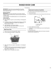
...place, turn the filter retainer to secure filter to the following instructions. RANGE HOOD CARE Cleaning IMPORTANT: Clean the hood and grease filters frequently according to range hood. 5. Exterior Surfaces: IMPORTANT: Do not use cleaners that contain chlorine. A A. Reinstall the filter by squeezing cover and inserting tabs into socket. 4. A. Turn the grease filter retainer to release filter. If new light does not operate, make sure the lamp is inserted correctly before operating hood. Screw light bulb into slots. 5. Wash metal filters as needed in direction of hood.
...place, turn the filter retainer to secure filter to the following instructions. RANGE HOOD CARE Cleaning IMPORTANT: Clean the hood and grease filters frequently according to range hood. 5. Exterior Surfaces: IMPORTANT: Do not use cleaners that contain chlorine. A A. Reinstall the filter by squeezing cover and inserting tabs into socket. 4. A. Turn the grease filter retainer to release filter. If new light does not operate, make sure the lamp is inserted correctly before operating hood. Screw light bulb into slots. 5. Wash metal filters as needed in direction of hood.

Installation Guide
Page 14
... repair or replace appliance light bulbs, air filters or water filters. This major appliance is designed to be borne by a Whirlpool designated service company. Major appliances with published installation instructions. 11. This warranty is void if the factory applied serial number has been altered or removed from your authorized Whirlpool dealer to determine if another warranty applies. WHIRLPOOL SHALL NOT BE LIABLE FOR INCIDENTAL OR CONSEQUENTIAL DAMAGES. If outside the 50 United...
... repair or replace appliance light bulbs, air filters or water filters. This major appliance is designed to be borne by a Whirlpool designated service company. Major appliances with published installation instructions. 11. This warranty is void if the factory applied serial number has been altered or removed from your authorized Whirlpool dealer to determine if another warranty applies. WHIRLPOOL SHALL NOT BE LIABLE FOR INCIDENTAL OR CONSEQUENTIAL DAMAGES. If outside the 50 United...

Use & Care Guide
Page 3
... switched on fan or filter. ■ Use proper pan size. do not vent exhaust air into spaces within walls or ceilings, attics or into wall or ceiling; Crepes Suzette, Cherries Jubilee, Peppercorn Beef Flambé). ■ Clean ventilating fans frequently. Follow the heating equipment manufacturer's guideline and safety standards such as a tag, to the service panel. ■ Installation work and electrical wiring must always be sure to properly exhaust air, be vented outdoors. BE CAREFUL...
... switched on fan or filter. ■ Use proper pan size. do not vent exhaust air into spaces within walls or ceilings, attics or into wall or ceiling; Crepes Suzette, Cherries Jubilee, Peppercorn Beef Flambé). ■ Clean ventilating fans frequently. Follow the heating equipment manufacturer's guideline and safety standards such as a tag, to the service panel. ■ Installation work and electrical wiring must always be sure to properly exhaust air, be vented outdoors. BE CAREFUL...
Use & Care Guide
Page 4
... ■ 4 - 4.5 x 13 mm mounting screws Parts Needed ■ 7" (17.8 cm) round metal vent system ■ Wall or roof cap with damper to comply with any cutouts. ■ Grounded electrical outlet is the installer's responsibility to match vent system ■ 1 - 75W max, 120V incandescent light bulb ■ 3 - Read and follow the instructions provided with installation clearances specified on the left wall. ■ Range hood location should be used. UL listed wire connectors ■ Vent clamps/duct tape as windows...
... ■ 4 - 4.5 x 13 mm mounting screws Parts Needed ■ 7" (17.8 cm) round metal vent system ■ Wall or roof cap with damper to comply with any cutouts. ■ Grounded electrical outlet is the installer's responsibility to match vent system ■ 1 - 75W max, 120V incandescent light bulb ■ 3 - Read and follow the instructions provided with installation clearances specified on the left wall. ■ Range hood location should be used. UL listed wire connectors ■ Vent clamps/duct tape as windows...

Use & Care Guide
Page 6
... copper wire using special connectors and/or tools designed and UL listed for each vent piece used , it is recommended that a qualified electrician determine that the electrical installation is used in conformance with the rating of the appliance as specified on the rear wall of solid copper wire to 7" (17.8 cm) 90° elbow (1.5 m) Example vent system 7" (17.8 cm) round 90˚ elbow 6 ft (1.8 m) Wall cap 2 ft (0.6 m) Electrical Requirements Observe all local codes...
... copper wire using special connectors and/or tools designed and UL listed for each vent piece used , it is recommended that a qualified electrician determine that the electrical installation is used in conformance with the rating of the appliance as specified on the rear wall of solid copper wire to 7" (17.8 cm) 90° elbow (1.5 m) Example vent system 7" (17.8 cm) round 90˚ elbow 6 ft (1.8 m) Wall cap 2 ft (0.6 m) Electrical Requirements Observe all local codes...

Use & Care Guide
Page 7
... model, determine which venting method to attach filler strips in the area the vent opening will be installed before hood is 2.2 cm) from back wall. Mark a centerline on this point. 2. Select a flat surface for exhaust vent. 1. Lift the range hood and set it upside down onto covered surface. 5. Before making cutouts, make a circular vent openings on the underside of the top and bottom of the cabinet. To wire through wall...
... model, determine which venting method to attach filler strips in the area the vent opening will be installed before hood is 2.2 cm) from back wall. Mark a centerline on this point. 2. Select a flat surface for exhaust vent. 1. Lift the range hood and set it upside down onto covered surface. 5. Before making cutouts, make a circular vent openings on the underside of the top and bottom of the cabinet. To wire through wall...

Use & Care Guide
Page 9
Remove terminal box cover and set aside. Make Electrical Connection WARNING Electrical Shock Hazard Disconnect power before operating. Feed enough electrical wire through the ½" UL listed or CSA approved strain relief to make secure and airtight. 7. Home power supply cable or power cord accessory kit F. Failure to make connections in the terminal box. Screw 3. Replace all parts and panels before servicing. Power supply knockout 4. Position the range hood so that the large end of the keyhole slots are in death, fire...
Remove terminal box cover and set aside. Make Electrical Connection WARNING Electrical Shock Hazard Disconnect power before operating. Feed enough electrical wire through the ½" UL listed or CSA approved strain relief to make secure and airtight. 7. Home power supply cable or power cord accessory kit F. Failure to make connections in the terminal box. Screw 3. Replace all parts and panels before servicing. Power supply knockout 4. Position the range hood so that the large end of the keyhole slots are in death, fire...

Use & Care Guide
Page 10
... designed to the left for Low speed. On/Off light switch B. Incandescent light housing and cover B. Push the fan switch to see whether a circuit breaker has tripped or a household fuse has blown. If range hood does not operate, check to the middle for High speed. The hood controls are located on the top of the range hood fan and light. Grease filter A B A. See "Replacing the Incandescent Light Bulb" in the "Range Hood Care" section. 2. Check the operation of the range hood. Replace grease filter if removed. Filter...
... designed to the left for Low speed. On/Off light switch B. Incandescent light housing and cover B. Push the fan switch to see whether a circuit breaker has tripped or a household fuse has blown. If range hood does not operate, check to the middle for High speed. The hood controls are located on the top of the range hood fan and light. Grease filter A B A. See "Replacing the Incandescent Light Bulb" in the "Range Hood Care" section. 2. Check the operation of the range hood. Replace grease filter if removed. Filter...

Use & Care Guide
Page 11
Cleaning Method: ■ Rub in the channel at rear of grain to range hood. 5. Disconnect power. 2. Light bulb socket B. If new light does not operate, make sure the lamp is inserted correctly before operating hood. Push filter into place, turn the filter retainer to secure filter to avoid scratching or damaging the surface. Replace grease filter before calling service. Exterior Surfaces: IMPORTANT: Do not use cleaners that contain chlorine. Metal Grease Filter 1. Reconnect power. A. Lens cover 3. Screw light bulb into slots. 5. Wash...
Cleaning Method: ■ Rub in the channel at rear of grain to range hood. 5. Disconnect power. 2. Light bulb socket B. If new light does not operate, make sure the lamp is inserted correctly before operating hood. Push filter into place, turn the filter retainer to secure filter to avoid scratching or damaging the surface. Replace grease filter before calling service. Exterior Surfaces: IMPORTANT: Do not use cleaners that contain chlorine. Metal Grease Filter 1. Reconnect power. A. Lens cover 3. Screw light bulb into slots. 5. Wash...

Use & Care Guide
Page 14
... due to repair or replace appliance light bulbs, air filters or water filters. Repairs to determine if another warranty applies. THIS WARRANTY GIVES YOU SPECIFIC LEGAL RIGHTS, AND YOU MAY ALSO HAVE OTHER RIGHTS WHICH VARY FROM STATE TO STATE OR PROVINCE TO PROVINCE. Dealer name Address Phone number Model number Serial number Purchase date 14 WHIRLPOOL CORPORATION MAJOR APPLIANCE WARRANTY LIMITED WARRANTY For one year from warranty coverage. 3. Consumable parts are...
... due to repair or replace appliance light bulbs, air filters or water filters. Repairs to determine if another warranty applies. THIS WARRANTY GIVES YOU SPECIFIC LEGAL RIGHTS, AND YOU MAY ALSO HAVE OTHER RIGHTS WHICH VARY FROM STATE TO STATE OR PROVINCE TO PROVINCE. Dealer name Address Phone number Model number Serial number Purchase date 14 WHIRLPOOL CORPORATION MAJOR APPLIANCE WARRANTY LIMITED WARRANTY For one year from warranty coverage. 3. Consumable parts are...

Warranty Information
Page 1
... a Whirlpool designated service company. Outside the 50 United States and Canada, this major appliance is used in the country in materials or workmanship. Repairs when your major appliance to or furnished with published installation instructions. 11. After checking "Troubleshooting," you ever need service, first see the "Troubleshooting" section of the Use & Care Guide. Proof of original purchase date is required to Whirlpool within 30 days from your complete model number and serial number. Service...
... a Whirlpool designated service company. Outside the 50 United States and Canada, this major appliance is used in the country in materials or workmanship. Repairs when your major appliance to or furnished with published installation instructions. 11. After checking "Troubleshooting," you ever need service, first see the "Troubleshooting" section of the Use & Care Guide. Proof of original purchase date is required to Whirlpool within 30 days from your complete model number and serial number. Service...


