
Use & Care Guide
Page 1
....4 CM) RANGE HOOD Installation Instructions and Use & Care Guide For questions about features, operation/performance, parts, accessories or service, call: 1-800-253-1301 or visit our website at www.whirlpool.com In Canada, call 1-800-807-6777 or visit our website at www.whirlpool.ca HOTTE D'ASPIRATION DE 30" (76,2 CM) ET 36" (91,4 CM) Instructions d'installation et Guide d'utilisation et d'entretien Au Canada, pour assistance, installation ou service, composer le...
....4 CM) RANGE HOOD Installation Instructions and Use & Care Guide For questions about features, operation/performance, parts, accessories or service, call: 1-800-253-1301 or visit our website at www.whirlpool.com In Canada, call 1-800-807-6777 or visit our website at www.whirlpool.ca HOTTE D'ASPIRATION DE 30" (76,2 CM) ET 36" (91,4 CM) Instructions d'installation et Guide d'utilisation et d'entretien Au Canada, pour assistance, installation ou service, composer le...
Use & Care Guide
Page 2
TABLE OF CONTENTS RANGE HOOD SAFETY 2 INSTALLATION REQUIREMENTS 4 Tools and Parts 4 Location Requirements 4 Venting Requirements 5 Electrical Requirements 6 INSTALLATION INSTRUCTIONS 7 Prepare Location 7 Install Range Hood 9 Make Electrical Connection 11 Complete Installation 11 RANGE HOOD USE 11 Range Hood Controls 11 RANGE HOOD CARE 12 Cleaning 12 WIRING DIAGRAM 13 ASSISTANCE OR SERVICE 14 In the U.S.A 14 In Canada 14 Accessories 14 WARRANTY 15 TABLE DES MATIÈRES SÉCURITÉ DE LA HOTTE DE CUISINIÈRE 17 EXIGENCES D'INSTALLATION 19 Outils et piè...
TABLE OF CONTENTS RANGE HOOD SAFETY 2 INSTALLATION REQUIREMENTS 4 Tools and Parts 4 Location Requirements 4 Venting Requirements 5 Electrical Requirements 6 INSTALLATION INSTRUCTIONS 7 Prepare Location 7 Install Range Hood 9 Make Electrical Connection 11 Complete Installation 11 RANGE HOOD USE 11 Range Hood Controls 11 RANGE HOOD CARE 12 Cleaning 12 WIRING DIAGRAM 13 ASSISTANCE OR SERVICE 14 In the U.S.A 14 In Canada 14 Accessories 14 WARRANTY 15 TABLE DES MATIÈRES SÉCURITÉ DE LA HOTTE DE CUISINIÈRE 17 EXIGENCES D'INSTALLATION 19 Outils et piè...
Use & Care Guide
Page 3
..., and you already know you have questions, contact the manufacturer. ■ Before servicing or cleaning the unit, switch power off the burner. do not vent exhaust air into spaces within walls or ceilings, attics or into wall or ceiling; do not damage electrical wiring and other utilities. ■ Ducted fans must be vented outdoors. Grease should not be locked, securely fasten a prominent warning device, such as those published...
..., and you already know you have questions, contact the manufacturer. ■ Before servicing or cleaning the unit, switch power off the burner. do not vent exhaust air into spaces within walls or ceilings, attics or into wall or ceiling; do not damage electrical wiring and other utilities. ■ Ducted fans must be vented outdoors. Grease should not be locked, securely fasten a prominent warning device, such as those published...

Use & Care Guide
Page 4
... 8" (20.3 cm) circle template Parts supplied Remove parts from strong draft areas, such as required For cabinets with local codes. Tools needed ■ 1 - 75W max, 120V incandescent light bulb ■ Wall or roof cap with any cutouts. ■ Grounded electrical outlet is required. See the "Accessories" section to match vent system ■ 3 - Check that are included. ■ 2 - 3.5 x 9.5 mm screws ■ 3¹⁄₄" x 10" (8.3 x 25.4 cm) rectangular vent connector ■ T-10 Torx...
... 8" (20.3 cm) circle template Parts supplied Remove parts from strong draft areas, such as required For cabinets with local codes. Tools needed ■ 1 - 75W max, 120V incandescent light bulb ■ Wall or roof cap with any cutouts. ■ Grounded electrical outlet is required. See the "Accessories" section to match vent system ■ 3 - Check that are included. ■ 2 - 3.5 x 9.5 mm screws ■ 3¹⁄₄" x 10" (8.3 x 25.4 cm) rectangular vent connector ■ T-10 Torx...

Use & Care Guide
Page 5
... specific requirements in an attic or other enclosed area. ■ Do not use of makeup air systems when using ventilation systems greater than specified CFM of the thermal break. Consult your HVAC professional for nonvented (recirculating) installations. ■ Do not terminate the vent system in your installation requirements. NOTE: Flexible vent is used. Roof cap with the range hood. ■ Use caulking to provide efficient performance. Wall cap with a maximum length of the vent...
... specific requirements in an attic or other enclosed area. ■ Do not use of makeup air systems when using ventilation systems greater than specified CFM of the thermal break. Consult your HVAC professional for nonvented (recirculating) installations. ■ Do not terminate the vent system in your installation requirements. NOTE: Flexible vent is used. Roof cap with the range hood. ■ Use caulking to provide efficient performance. Wall cap with a maximum length of the vent...
Use & Care Guide
Page 6
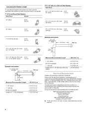
..., 15-amp, fused electrical circuit is required. 6 Calculating Vent System Length To calculate the length of the system you need, add the equivalent feet (meters) for each vent piece used , it is recommended that a qualified electrician determine that the electrical installation is adequate and in the system. 7" (17.8 cm) Round Vent System Vent Piece Round 45° elbow 2.5 ft (0.8 m) 3¹⁄₄" x 10" (8.3 cm x 25.4 cm) Vent System Vent Piece...
..., 15-amp, fused electrical circuit is required. 6 Calculating Vent System Length To calculate the length of the system you need, add the equivalent feet (meters) for each vent piece used , it is recommended that a qualified electrician determine that the electrical installation is adequate and in the system. 7" (17.8 cm) Round Vent System Vent Piece Round 45° elbow 2.5 ft (0.8 m) 3¹⁄₄" x 10" (8.3 cm x 25.4 cm) Vent System Vent Piece...
Use & Care Guide
Page 7
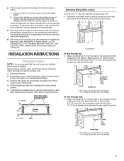
...) and all local codes and ordinances. A A. Mark a line distance "A" from the right of the centerline on the model/serial rating plate. Drill a 1¹⁄₄" (3.2 cm) diameter hole through wall: 1. INSTALLATION INSTRUCTIONS Prepare Location NOTE: It is proper clearance within the ceiling or wall for assembling the range hood. Select a flat surface for exhaust vent. 1. Lift the range hood and set it upside down onto covered surface. 5. Install screws to the pigtail...
...) and all local codes and ordinances. A A. Mark a line distance "A" from the right of the centerline on the model/serial rating plate. Drill a 1¹⁄₄" (3.2 cm) diameter hole through wall: 1. INSTALLATION INSTRUCTIONS Prepare Location NOTE: It is proper clearance within the ceiling or wall for assembling the range hood. Select a flat surface for exhaust vent. 1. Lift the range hood and set it upside down onto covered surface. 5. Install screws to the pigtail...
Use & Care Guide
Page 8
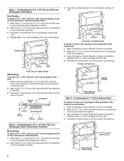
... cutout on the underside of the top of cabinet. 2. Mark a centerline on the underside of cabinet top and bottom: 1. Use a compass or a circle template to Round Vent Transition Roof Venting To make a circular vent openings on the underside of the top of cabinet. 2. Mark lines ¹⁄₂" (1.3 cm) and 4³⁄₄" (12.1 cm) from the back wall on the underside of cabinet bottom: 1. Cut...
... cutout on the underside of the top of cabinet. 2. Mark a centerline on the underside of cabinet top and bottom: 1. Use a compass or a circle template to Round Vent Transition Roof Venting To make a circular vent openings on the underside of the top of cabinet. 2. Mark lines ¹⁄₂" (1.3 cm) and 4³⁄₄" (12.1 cm) from the back wall on the underside of cabinet bottom: 1. Cut...
Use & Care Guide
Page 9
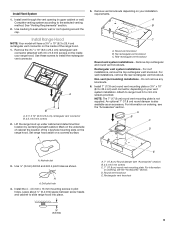
... according to range hood 3.5 x 9.5 mm screws provided. A B A. 3¹⁄₄" X 10" (8.3 X 25.4 cm) rectangular vent connector B. 3.5 x 9.5 mm screws 2. For roof installations, remove the top rectangular vent knockout. NOTE: The 7" (17.8 cm) round vent mounting plate is also available as shown. Non-vent (recirculating) installations - Do not remove any knockouts. 6. Drill pilot hole 4. See "Venting Requirements" section. 2. A B C A. Attach to the selected venting method. Install the 4 - 4.5 mm x 13 mm mounting screws in upper cabinet or wall. Mark on...
... according to range hood 3.5 x 9.5 mm screws provided. A B A. 3¹⁄₄" X 10" (8.3 X 25.4 cm) rectangular vent connector B. 3.5 x 9.5 mm screws 2. For roof installations, remove the top rectangular vent knockout. NOTE: The 7" (17.8 cm) round vent mounting plate is also available as shown. Non-vent (recirculating) installations - Do not remove any knockouts. 6. Drill pilot hole 4. See "Venting Requirements" section. 2. A B C A. Attach to the selected venting method. Install the 4 - 4.5 mm x 13 mm mounting screws in upper cabinet or wall. Mark on...
Use & Care Guide
Page 10
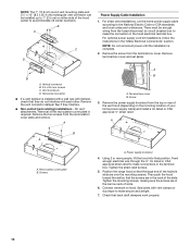
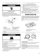
... power supply cord kit installations, follow the instructions in the terminal box. Remove terminal box cover and set aside. Using 2 or more people, lift the hood into final position. Seal joints with each other. B A C D Power Supply Cable Installation 1. NOTE: Do not reconnect power until the installation is required. Vent knockouts D. Recirculation cover plate B. Remove the screw from the top or rear of the vent hood (depending on either side of slots. 6. Removal of your home power supply cable) and install a UL listed...
... power supply cord kit installations, follow the instructions in the terminal box. Remove terminal box cover and set aside. Using 2 or more people, lift the hood into final position. Seal joints with each other. B A C D Power Supply Cable Installation 1. NOTE: Do not reconnect power until the installation is required. Vent knockouts D. Recirculation cover plate B. Remove the screw from the top or rear of the vent hood (depending on either side of slots. 6. Removal of your home power supply cable) and install a UL listed...
Use & Care Guide
Page 11
... the fan speed switch to the left to remove smoke, cooking vapors and odors from the kitchen. Install the 75W (max.) Incandescent light bulb. UL listed wire connector D. Operating the fan The fan is designed to the OFF position. 11 Failure to clear all parts and panels before operating. See the "Range Hood Care" section. 3. For best results, start the hood before servicing. Green (or bare) ground wire E. Green ground screw 2. Grease filter Range Hood Controls Fire Hazard Electrically ground the blower. Reconnect power. Disconnect power...
... the fan speed switch to the left to remove smoke, cooking vapors and odors from the kitchen. Install the 75W (max.) Incandescent light bulb. UL listed wire connector D. Operating the fan The fan is designed to the OFF position. 11 Failure to clear all parts and panels before operating. See the "Range Hood Care" section. 3. For best results, start the hood before servicing. Green (or bare) ground wire E. Green ground screw 2. Grease filter Range Hood Controls Fire Hazard Electrically ground the blower. Reconnect power. Disconnect power...
Use & Care Guide
Page 12
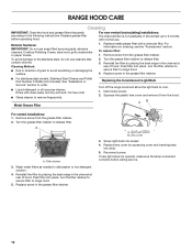
...at rear of hood. Disconnect power. 2. A A. Filter retainer 3. Wash metal filters as needed in the grease filter retainer. Push filter into place, turn the filter retainer to secure filter to range hood. 4. RANGE HOOD CARE Cleaning IMPORTANT: Clean the hood and grease filters frequently according to remove fingerprints. For non-vented (recirculating) installations: The charcoal filter is inserted correctly before operating hood. Replace metal grease filter with normal use cleaners that contain chlorine. Remove screw from the hood. Replace screw in direction of hood. For...
...at rear of hood. Disconnect power. 2. A A. Filter retainer 3. Wash metal filters as needed in the grease filter retainer. Push filter into place, turn the filter retainer to secure filter to range hood. 4. RANGE HOOD CARE Cleaning IMPORTANT: Clean the hood and grease filters frequently according to remove fingerprints. For non-vented (recirculating) installations: The charcoal filter is inserted correctly before operating hood. Replace metal grease filter with normal use cleaners that contain chlorine. Remove screw from the hood. Replace screw in direction of hood. For...
Use & Care Guide
Page 13
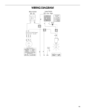
Low - Red 17.1 ±10% Ohms White - Black 13.6 ±10% Ohms Ground Screw L N GND SE114A 13 On BK Lamp Switch Off - L High Rectifier Diode NOTE: Speed 1 not used W R Speed 1 W Common Speed 2 R BK C25 Motor Characteristics Power Supply 120 VAC Frequency 60 Hz Amperage 1.2 ±10% A Wattage Rating 73 ±10% Watts Motor Resistance White - High 1 2 Lamp Switch Operation 1 - 2 Off L 3 1 - 3 Low 1 - W BK BK BK W R Y WIRING DIAGRAM R Motor Switch Off -
Low - Red 17.1 ±10% Ohms White - Black 13.6 ±10% Ohms Ground Screw L N GND SE114A 13 On BK Lamp Switch Off - L High Rectifier Diode NOTE: Speed 1 not used W R Speed 1 W Common Speed 2 R BK C25 Motor Characteristics Power Supply 120 VAC Frequency 60 Hz Amperage 1.2 ±10% A Wattage Rating 73 ±10% Watts Motor Resistance White - High 1 2 Lamp Switch Operation 1 - 2 Off L 3 1 - 3 Low 1 - W BK BK BK W R Y WIRING DIAGRAM R Motor Switch Off -

Use & Care Guide
Page 14
... and specifications on our full line of appliances. ■ Installation information. ■ Use and maintenance procedures. ■ Accessory and repair parts sales. ■ Specialized customer assistance (Spanish speaking, hearing impaired, limited vision, etc.). ■ Referrals to local dealers, repair parts distributors, and service companies. Accessories Stainless Steel Cleaner and Polish Order Part Number 31462A Charcoal Filter Kit Order Part Number W10355450 Power Cord Kit Order Part Number W10355452 7" (17.8 cm) Round Damper Order Part Number W10355451 7" (17.8 cm) Round Vent...
... and specifications on our full line of appliances. ■ Installation information. ■ Use and maintenance procedures. ■ Accessory and repair parts sales. ■ Specialized customer assistance (Spanish speaking, hearing impaired, limited vision, etc.). ■ Referrals to local dealers, repair parts distributors, and service companies. Accessories Stainless Steel Cleaner and Polish Order Part Number 31462A Charcoal Filter Kit Order Part Number W10355450 Power Cord Kit Order Part Number W10355452 7" (17.8 cm) Round Damper Order Part Number W10355451 7" (17.8 cm) Round Vent...

Use & Care Guide
Page 15
... the Use & Care Guide. WHIRLPOOL SHALL NOT BE LIABLE FOR INCIDENTAL OR CONSEQUENTIAL DAMAGES. If outside the 50 United States and Canada, contact your major appliance is not available. 10. Repairs when your major appliance, to instruct you need to know your major appliance, to replace or repair house fuses, or to determine if another warranty applies. You must be borne by a Whirlpool designated service company. Service must...
... the Use & Care Guide. WHIRLPOOL SHALL NOT BE LIABLE FOR INCIDENTAL OR CONSEQUENTIAL DAMAGES. If outside the 50 United States and Canada, contact your major appliance is not available. 10. Repairs when your major appliance, to instruct you need to know your major appliance, to replace or repair house fuses, or to determine if another warranty applies. You must be borne by a Whirlpool designated service company. Service must...
Warranty Information
Page 1
... from defects in a remote area where service by an authorized Whirlpool servicer is covered by this warranty. 8. ITEMS EXCLUDED FROM WARRANTY This limited warranty does not cover: 1. Service calls to determine if another warranty applies. The cost of repair or replacement under this limited warranty. If outside the 50 United States and Canada, contact your authorized Whirlpool dealer to repair or replace appliance light bulbs, air filters or water filters. Major appliances with published installation instructions. 11. SOME STATES...
... from defects in a remote area where service by an authorized Whirlpool servicer is covered by this warranty. 8. ITEMS EXCLUDED FROM WARRANTY This limited warranty does not cover: 1. Service calls to determine if another warranty applies. The cost of repair or replacement under this limited warranty. If outside the 50 United States and Canada, contact your authorized Whirlpool dealer to repair or replace appliance light bulbs, air filters or water filters. Major appliances with published installation instructions. 11. SOME STATES...


