

Use & Care Guide
Page 1
.... 30" (76.2 CM) AND 36" (91.4 CM) RANGE HOOD Installation Instructions and Use & Care Guide For questions about features, operation/performance, parts, accessories or service, call: 1-800-253-1301 or visit our website at www.whirlpool.com In Canada, call 1-800-807-6777 or visit our website at... d'utilisation et d'entretien Au Canada, pour assistance, installation ou service, composer le 1-800-807-6777 ou visiter notre site Web à www.whirlpool.ca Table of Contents/Table des matières 2 Models/Modèles: UXT5230AY/UXT5236AY IMPORTANT: READ AND SAVE THESE INSTRUCTIONS. IMPORTANT : LIRE...
.... 30" (76.2 CM) AND 36" (91.4 CM) RANGE HOOD Installation Instructions and Use & Care Guide For questions about features, operation/performance, parts, accessories or service, call: 1-800-253-1301 or visit our website at www.whirlpool.com In Canada, call 1-800-807-6777 or visit our website at... d'utilisation et d'entretien Au Canada, pour assistance, installation ou service, composer le 1-800-807-6777 ou visiter notre site Web à www.whirlpool.ca Table of Contents/Table des matières 2 Models/Modèles: UXT5230AY/UXT5236AY IMPORTANT: READ AND SAVE THESE INSTRUCTIONS. IMPORTANT : LIRE...

Use & Care Guide
Page 2
...Parts 4 Location Requirements 4 Venting Requirements 5 Electrical Requirements 6 INSTALLATION INSTRUCTIONS 7 Prepare Location 7 Install Range Hood 9 Make Electrical Connection 11 Complete Installation 11 RANGE HOOD USE 12 Range Hood Controls 12 RANGE HOOD CARE 12 Cleaning 12 WIRING DIAGRAM 14 ASSISTANCE OR SERVICE 15 In the U.S.A 15 In Canada 15 Accessories...;MA DE CÂBLAGE 30 ASSISTANCE OU SERVICE 31 Au Canada 31 Accessoires 31 GARANTIE 31 RANGE HOOD SAFETY Your safety and the safety of injury, and tell you what can happen if the instructions are very important.
...Parts 4 Location Requirements 4 Venting Requirements 5 Electrical Requirements 6 INSTALLATION INSTRUCTIONS 7 Prepare Location 7 Install Range Hood 9 Make Electrical Connection 11 Complete Installation 11 RANGE HOOD USE 12 Range Hood Controls 12 RANGE HOOD CARE 12 Cleaning 12 WIRING DIAGRAM 14 ASSISTANCE OR SERVICE 15 In the U.S.A 15 In Canada 15 Accessories...;MA DE CÂBLAGE 30 ASSISTANCE OU SERVICE 31 Au Canada 31 Accessoires 31 GARANTIE 31 RANGE HOOD SAFETY Your safety and the safety of injury, and tell you what can happen if the instructions are very important.

Use & Care Guide
Page 3
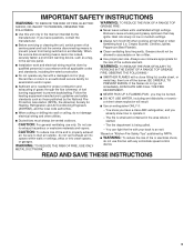
... TO PREVENT BURNS. you may ignite. You can fight the fire with any fan with a close fitting lid, cookie sheet, or metal tray, then turn hood ON when cooking at high heat or when flambeing food (i.e. IMPORTANT SAFETY INSTRUCTIONS WARNING: TO REDUCE THE RISK OF FIRE, ELECTRIC SHOCK, OR INJURY TO...
... TO PREVENT BURNS. you may ignite. You can fight the fire with any fan with a close fitting lid, cookie sheet, or metal tray, then turn hood ON when cooking at high heat or when flambeing food (i.e. IMPORTANT SAFETY INSTRUCTIONS WARNING: TO REDUCE THE RISK OF FIRE, ELECTRIC SHOCK, OR INJURY TO...

Use & Care Guide
Page 4
.... Tools needed ■ Wall or roof cap with installation clearances specified on the left wall. ■ Range hood location should be sealed. ■ These range hoods are factory set for pilot holes ■ Pencil ■ Wire stripper or utility knife ■ Tape measure ...range manufacturer installation instructions before starting installation. See "Electrical Requirements" section. ■ All openings in ceiling and wall where range hood will be installed must conform to the Manufactured Home Construction Safety Standards, Title 24 CFR, Part 328 (formerly the Federal Standard ...
.... Tools needed ■ Wall or roof cap with installation clearances specified on the left wall. ■ Range hood location should be sealed. ■ These range hoods are factory set for pilot holes ■ Pencil ■ Wire stripper or utility knife ■ Tape measure ...range manufacturer installation instructions before starting installation. See "Electrical Requirements" section. ■ All openings in ceiling and wall where range hood will be installed must conform to the Manufactured Home Construction Safety Standards, Title 24 CFR, Part 328 (formerly the Federal Standard ...

Use & Care Guide
Page 5
...locale to 30" (76.2 cm) max. NOTE: Flexible vent is recommended. clearance - Rigid metal vent is not recommended. Roof cap with the range hood. ■ Use caulking to seal exterior wall or roof opening width for vent system. cabinet opening around the cap. D. 13" (33.0 cm) ... Use a 7" (17.8 cm) round metal vent or a 3¹⁄₄" x 10" (8.3 x 25.4 cm) rectangular metal vent, depending on the cold air side of range hood to 30" (76.2 cm) max. Use 3¹⁄₄" x 10" (8.3 x 25.4 cm) rectangular with a maximum vent length of 35 ft (10.7 m) or 7" (...
...locale to 30" (76.2 cm) max. NOTE: Flexible vent is recommended. clearance - Rigid metal vent is not recommended. Roof cap with the range hood. ■ Use caulking to seal exterior wall or roof opening width for vent system. cabinet opening around the cap. D. 13" (33.0 cm) ... Use a 7" (17.8 cm) round metal vent or a 3¹⁄₄" x 10" (8.3 x 25.4 cm) rectangular metal vent, depending on the cold air side of range hood to 30" (76.2 cm) max. Use 3¹⁄₄" x 10" (8.3 x 25.4 cm) rectangular with a maximum vent length of 35 ft (10.7 m) or 7" (...

Use & Care Guide
Page 6
... = 35 ft (10.7 m) 1 - 90° elbow 8 ft (2.4 m) straight 1 - Ensure that the ground path is located behind the filter on the rear wall of the range hood. ■ Wire sizes must conform with the rating of the appliance as specified on the model/serial rating plate. Connect a section of solid copper wire...
... = 35 ft (10.7 m) 1 - 90° elbow 8 ft (2.4 m) straight 1 - Ensure that the ground path is located behind the filter on the rear wall of the range hood. ■ Wire sizes must conform with the rating of the appliance as specified on the model/serial rating plate. Connect a section of solid copper wire...
Use & Care Guide
Page 7
... a 1¹⁄₄" (3.2 cm) diameter hole through the cabinet at this line that surface. 4. See Step 2 for assembling the range hood. Determine Wiring Hole Location Cut only one 1¹⁄₄" (3.2 cm) diameter wiring access hole. Determine and clearly mark a vertical centerline on... roof, wall or non-vented (recirculating). 3. Disconnect power. Mark the point on the underside of the centerline on this point. 2. Lift the range hood and set it upside down onto covered surface. 5. Before making cutouts, make a 4¹⁄₄" x 10½" (10.8 cm x 26.7...
... a 1¹⁄₄" (3.2 cm) diameter hole through the cabinet at this line that surface. 4. See Step 2 for assembling the range hood. Determine Wiring Hole Location Cut only one 1¹⁄₄" (3.2 cm) diameter wiring access hole. Determine and clearly mark a vertical centerline on... roof, wall or non-vented (recirculating). 3. Disconnect power. Mark the point on the underside of the centerline on this point. 2. Lift the range hood and set it upside down onto covered surface. 5. Before making cutouts, make a 4¹⁄₄" x 10½" (10.8 cm x 26.7...

Use & Care Guide
Page 9
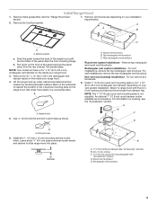
...(recirculating) installations - Round vent knockout E. Keyhole slot 5. Leave about ¹⁄₄" (6.4 cm) space between screw heads and cabinet to range hood with the 3.5 x 5 mm screws provided and remove tape from the rear channel. Remove the 3¼" x 10" (8.3 x 25.4 cm) ....8 cm) round vent mounting plate is also available as shown. A B C D A A. Install Range Hood 1. Remove metal grease filter. See the "Range Hood Care" section. 7. Set range hood aside on the front of the panel clear the front mounting flange. For wall installations, remove the rear rectangular...
...(recirculating) installations - Round vent knockout E. Keyhole slot 5. Leave about ¹⁄₄" (6.4 cm) space between screw heads and cabinet to range hood with the 3.5 x 5 mm screws provided and remove tape from the rear channel. Remove the 3¼" x 10" (8.3 x 25.4 cm) ....8 cm) round vent mounting plate is also available as shown. A B C D A A. Install Range Hood 1. Remove metal grease filter. See the "Range Hood Care" section. 7. Set range hood aside on the front of the panel clear the front mounting flange. For wall installations, remove the rear rectangular...
Use & Care Guide
Page 10
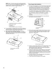
...mounting screws. Remove terminal box cover and set aside. Vertical vent connector with damper, check that the screws are in the hood electrical terminal box. Remove the vent connector damper flap if they do not interfere with vent clamps or duct tape to ... draft dampers work properly. 10 Check that the large end of the slots. Remove the two screws from the top or rear of the vent hood (depending on the incoming location of slots. 6. Power supply knockout 4. Tighten the strain relief screws. 5. B A C D E Power Supply Cable Installation 1. Vent knockouts E. A A B ...
...mounting screws. Remove terminal box cover and set aside. Vertical vent connector with damper, check that the screws are in the hood electrical terminal box. Remove the vent connector damper flap if they do not interfere with vent clamps or duct tape to ... draft dampers work properly. 10 Check that the large end of the slots. Remove the two screws from the top or rear of the vent hood (depending on the incoming location of slots. 6. Power supply knockout 4. Tighten the strain relief screws. 5. B A C D E Power Supply Cable Installation 1. Vent knockouts E. A A B ...

Use & Care Guide
Page 11
... power. Failure to green ground screw in death, fire, or electrical shock. 4. Connect green (or bare) ground wire from your new range hood, read the "Range Hood Use" section. 11 b. Disconnect power and check wiring connections. G C D E A B F A. White wires B. Green (or bare)...Failure to green ground screw in death or electrical shock. 1. Green ground screw 2. Replace the 2 bottom panels. See the "Range Hood Care" section. 3. Make Electrical Connection WARNING 3. Use UL listed wire connectors and connect black wires (B) together. WARNING Electrical Shock ...
... power. Failure to green ground screw in death, fire, or electrical shock. 4. Connect green (or bare) ground wire from your new range hood, read the "Range Hood Use" section. 11 b. Disconnect power and check wiring connections. G C D E A B F A. White wires B. Green (or bare)...Failure to green ground screw in death or electrical shock. 1. Green ground screw 2. Replace the 2 bottom panels. See the "Range Hood Care" section. 3. Make Electrical Connection WARNING 3. Use UL listed wire connectors and connect black wires (B) together. WARNING Electrical Shock ...

Use & Care Guide
Page 12
.... ■ Liquid detergent or all smoke and odors from the filter retainer. 2. Filter retainer Range Hood Controls A B CD RANGE HOOD CARE Cleaning IMPORTANT: Clean the hood and grease filters frequently according to the stainless steel, do not use cleaners that contain chlorine. To .... A. The speed can be changed anytime during fan operation by pressing the desired blower speed button. Grease filter C. A B C A. The hood controls are located on ordering, see the "Accessories" section. For non-vented (recirculating) installations: The charcoal filter is complete to clear all -...
.... ■ Liquid detergent or all smoke and odors from the filter retainer. 2. Filter retainer Range Hood Controls A B CD RANGE HOOD CARE Cleaning IMPORTANT: Clean the hood and grease filters frequently according to the stainless steel, do not use cleaners that contain chlorine. To .... A. The speed can be changed anytime during fan operation by pressing the desired blower speed button. Grease filter C. A B C A. The hood controls are located on ordering, see the "Accessories" section. For non-vented (recirculating) installations: The charcoal filter is complete to clear all -...

Use & Care Guide
Page 13
...slot opening on the lens and turn it into place. 3. Replacing the Halogen Lamp Turn off the range hood and allow the halogen lamp to handle lamp. Disconnect power. 2. Remove the lamp and replace it with ...Reconnect power. 13 Place the back edge of the filter into the channel at the rear of the range hood. It will spring back into the filter retainer. Push up into place. 4. Release the filter retainer. To... filter up on the long edge of the filter is to be toward the front of the range hood and push the front of the new lamp, do not operate, make sure the lamps are inserted ...
...slot opening on the lens and turn it into place. 3. Replacing the Halogen Lamp Turn off the range hood and allow the halogen lamp to handle lamp. Disconnect power. 2. Remove the lamp and replace it with ...Reconnect power. 13 Place the back edge of the filter into the channel at the rear of the range hood. It will spring back into the filter retainer. Push up into place. 4. Release the filter retainer. To... filter up on the long edge of the filter is to be toward the front of the range hood and push the front of the new lamp, do not operate, make sure the lamps are inserted ...

Installation Guide
Page 1
...RÉSIDENTIELLE UNIQUEMENT. FOR RESIDENTIAL USE ONLY. IMPORTANT : LIRE ET CONSERVER CES INSTRUCTIONS. 30" (76.2 CM) AND 36" (91.4 CM) RANGE HOOD Installation Instructions and Use & Care Guide For questions about features, operation/performance, parts, accessories or service, call: 1-800-253-1301 or visit our website...et d'entretien Au Canada, pour assistance, installation ou service, composer le 1-800-807-6777 ou visiter notre site Web à www.whirlpool.ca Table of Contents/Table des matières 2 Models/Modèles: UXT5230AY/UXT5236AY IMPORTANT: READ AND SAVE THESE INSTRUCTIONS.
...RÉSIDENTIELLE UNIQUEMENT. FOR RESIDENTIAL USE ONLY. IMPORTANT : LIRE ET CONSERVER CES INSTRUCTIONS. 30" (76.2 CM) AND 36" (91.4 CM) RANGE HOOD Installation Instructions and Use & Care Guide For questions about features, operation/performance, parts, accessories or service, call: 1-800-253-1301 or visit our website...et d'entretien Au Canada, pour assistance, installation ou service, composer le 1-800-807-6777 ou visiter notre site Web à www.whirlpool.ca Table of Contents/Table des matières 2 Models/Modèles: UXT5230AY/UXT5236AY IMPORTANT: READ AND SAVE THESE INSTRUCTIONS.

Installation Guide
Page 2
... Location Requirements 4 Venting Requirements 5 Electrical Requirements 6 INSTALLATION INSTRUCTIONS 7 Prepare Location 7 Install Range Hood 9 Make Electrical Connection 11 Complete Installation 11 RANGE HOOD USE 12 Range Hood Controls 12 RANGE HOOD CARE 12 Cleaning 12 WIRING DIAGRAM 14 ASSISTANCE OR SERVICE 15 In the U.S.A 15 In Canada ... Nettoyage 28 SCHÉMA DE CÂBLAGE 30 ASSISTANCE OU SERVICE 31 Au Canada 31 Accessoires 31 GARANTIE 31 RANGE HOOD SAFETY Your safety and the safety of injury, and tell you don't follow the safety alert symbol and either the word...
... Location Requirements 4 Venting Requirements 5 Electrical Requirements 6 INSTALLATION INSTRUCTIONS 7 Prepare Location 7 Install Range Hood 9 Make Electrical Connection 11 Complete Installation 11 RANGE HOOD USE 12 Range Hood Controls 12 RANGE HOOD CARE 12 Cleaning 12 WIRING DIAGRAM 14 ASSISTANCE OR SERVICE 15 In the U.S.A 15 In Canada ... Nettoyage 28 SCHÉMA DE CÂBLAGE 30 ASSISTANCE OU SERVICE 31 Au Canada 31 Accessoires 31 GARANTIE 31 RANGE HOOD SAFETY Your safety and the safety of injury, and tell you don't follow the safety alert symbol and either the word...
Installation Guide
Page 3
... IN THE EVENT OF A RANGE TOP GREASE FIRE, OBSERVE THE FOLLOWING:a ■ SMOTHER FLAMES with a close fitting lid, cookie sheet, or metal tray, then turn hood ON when cooking at high settings. You can fight the fire with any fan with a damaged cord or plug. Follow the heating equipment manufacturer's guideline...
... IN THE EVENT OF A RANGE TOP GREASE FIRE, OBSERVE THE FOLLOWING:a ■ SMOTHER FLAMES with a close fitting lid, cookie sheet, or metal tray, then turn hood ON when cooking at high settings. You can fight the fire with any fan with a damaged cord or plug. Follow the heating equipment manufacturer's guideline...

Installation Guide
Page 4
...on ordering, see the "Accessories" section. Given dimensions provide minimum clearance. See "Electrical Requirements" section. ■ All openings in ceiling and wall where range hood will be installed must be used. Models that are included. ■ 2 - 3.5 x 5 mm screws ■ 3¹⁄₄" x 10"...metal vent system For non-vented (recirculation) installations: ■ Charcoal filter kit. For information on the left wall. ■ Range hood location should be away from package. Tools needed ■ Wall or roof cap with washers and nuts (to attach filler strips). Length...
...on ordering, see the "Accessories" section. Given dimensions provide minimum clearance. See "Electrical Requirements" section. ■ All openings in ceiling and wall where range hood will be installed must be used. Models that are included. ■ 2 - 3.5 x 5 mm screws ■ 3¹⁄₄" x 10"...metal vent system For non-vented (recirculation) installations: ■ Charcoal filter kit. For information on the left wall. ■ Range hood location should be away from package. Tools needed ■ Wall or roof cap with washers and nuts (to attach filler strips). Length...

Installation Guide
Page 5
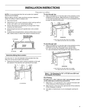
... as part of the vent system. Venting Methods Vent system can terminate either through the wall or out the top (purchased separately). bottom of range hood to 30" (76.2 cm) max. D. 13" (33.0 cm) cabinet depth E. 36" (91.4 cm) base cabinet height Venting Requirements ■ Vent system must terminate to the... with damper (purchased separately) C. 24" (61.0 cm) min. cabinet width for 30" (76.2 cm) models and 36" (91.4 cm) min. Wall cap with the range hood. ■ Use caulking to 30" (76.2 cm) max.
... as part of the vent system. Venting Methods Vent system can terminate either through the wall or out the top (purchased separately). bottom of range hood to 30" (76.2 cm) max. D. 13" (33.0 cm) cabinet depth E. 36" (91.4 cm) base cabinet height Venting Requirements ■ Vent system must terminate to the... with damper (purchased separately) C. 24" (61.0 cm) min. cabinet width for 30" (76.2 cm) models and 36" (91.4 cm) min. Wall cap with the range hood. ■ Use caulking to 30" (76.2 cm) max.

Installation Guide
Page 6
... codes permit and a separate ground wire is used in conformance with the rating of the appliance as specified on the rear wall of the range hood. ■ Wire sizes must conform with National Electrical Code, ANSI/NFPA 70 (latest edition), or CSA Standards C22.1-94, Canadian Electrical Code, Part 1 and C22...
... codes permit and a separate ground wire is used in conformance with the rating of the appliance as specified on the rear wall of the range hood. ■ Wire sizes must conform with National Electrical Code, ANSI/NFPA 70 (latest edition), or CSA Standards C22.1-94, Canadian Electrical Code, Part 1 and C22...

Installation Guide
Page 7
... (3.2 cm) diameter wiring access hole. Use saber or keyhole saw to attach filler strips in the area the vent opening for assembling the range hood. To wire through wall: 1. Cut Openings for wiring hole location instructions. 1. Mark the point on the underside of cabinet. 2. Mark lines ...³⁄₈" (28.9 cm) for 36" (91.4 cm) models Cabinet bottom 3" (7.6 cm) Wall To wire through top: 1. Lift the range hood and set it upside down onto covered surface. 5. A ⁷⁄₈" (2.2 cm) from the right of the centerline on the centerline of the underside...
... (3.2 cm) diameter wiring access hole. Use saber or keyhole saw to attach filler strips in the area the vent opening for assembling the range hood. To wire through wall: 1. Cut Openings for wiring hole location instructions. 1. Mark the point on the underside of cabinet. 2. Mark lines ...³⁄₈" (28.9 cm) for 36" (91.4 cm) models Cabinet bottom 3" (7.6 cm) Wall To wire through top: 1. Lift the range hood and set it upside down onto covered surface. 5. A ⁷⁄₈" (2.2 cm) from the right of the centerline on the centerline of the underside...
Installation Guide
Page 9
... vent knockout B. Rear rectangular vent knockout Round vent system installations - Non-vent (recirculating) installations - For information on the inside your range hood. 3. A B C D A A. Remove metal grease filter. b. Mark on the underside of cabinet the location of the panel clear ...185;⁄₈" (3 mm) drill bit and drill 4 pilot holes as an accessory. Rectangular vent system installations - Round vent knockout E. Attach to slide range hood into place. ¹⁄₄" (6.4 mm) E A. 7" (17.8 cm) Round damper (see "Accessories" section) B. 3.5 x 5 mm screws ...
... vent knockout B. Rear rectangular vent knockout Round vent system installations - Non-vent (recirculating) installations - For information on the inside your range hood. 3. A B C D A A. Remove metal grease filter. b. Mark on the underside of cabinet the location of the panel clear ...185;⁄₈" (3 mm) drill bit and drill 4 pilot holes as an accessory. Rectangular vent system installations - Round vent knockout E. Attach to slide range hood into place. ¹⁄₄" (6.4 mm) E A. 7" (17.8 cm) Round damper (see "Accessories" section) B. 3.5 x 5 mm screws ...


