
Owners Manual
Page 1
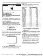
... Mexico, register your range at www.whirlpool.com. KNOB CONTROLS 4 COOKTOP CONTROLS - You may view them by rotating the serial plates up. The serial plates are located behind the control panel. KNOB CONTROLS 5 Dual/Triple-Circuit Element (on some models 5 Warm Zone Element (on some models 6 Home Canning 7 Cookware 7 COOKTOP CARE 7 General Cleaning 7 TROUBLESHOOTING 9 ASSISTANCE OR SERVICE 10 In the U.S.A 10 Accessories 10 In Canada 10 W11206695A ELECTRIC COOKTOP USER INSTRUCTIONS THANK YOU for purchasing this high-quality product. Los...
... Mexico, register your range at www.whirlpool.com. KNOB CONTROLS 4 COOKTOP CONTROLS - You may view them by rotating the serial plates up. The serial plates are located behind the control panel. KNOB CONTROLS 5 Dual/Triple-Circuit Element (on some models 5 Warm Zone Element (on some models 6 Home Canning 7 Cookware 7 COOKTOP CARE 7 General Cleaning 7 TROUBLESHOOTING 9 ASSISTANCE OR SERVICE 10 In the U.S.A 10 Accessories 10 In Canada 10 W11206695A ELECTRIC COOKTOP USER INSTRUCTIONS THANK YOU for purchasing this high-quality product. Los...

Owners Manual
Page 2
...manual and on your appliance. Always read and obey all safety messages. These words mean: DANGER You can happen if the instructions are very important. This is , tell you what the potential hazard is the safety alert symbol. All safety messages will follow instructions... if you and others are not followed. WARNING You can kill or hurt you don't follow instructions. This symbol alerts you don't immediately follow the safety alert symbol and either the word "DANGER... defects or other reproductive harm. 2 COOKTOP SAFETY Your safety and the safety of others .
...manual and on your appliance. Always read and obey all safety messages. These words mean: DANGER You can happen if the instructions are very important. This is , tell you what the potential hazard is the safety alert symbol. All safety messages will follow instructions... if you and others are not followed. WARNING You can kill or hurt you don't follow instructions. This symbol alerts you don't immediately follow the safety alert symbol and either the word "DANGER... defects or other reproductive harm. 2 COOKTOP SAFETY Your safety and the safety of others .

Owners Manual
Page 3
... Surface Units Unattended at High Heat Settings - CAUTION: The cooking process should never be supervised. To reduce the risk of burns, ignition of flammable materials, and spillage due to a qualified technician. Contact a qualified technician immediately. When flaming foods under the hood, turn the fan on Grease Fires - Improper installation of these pans or bowls during cooking may result in the manual. User Servicing - DO NOT TOUCH SURFACE...
... Surface Units Unattended at High Heat Settings - CAUTION: The cooking process should never be supervised. To reduce the risk of burns, ignition of flammable materials, and spillage due to a qualified technician. Contact a qualified technician immediately. When flaming foods under the hood, turn the fan on Grease Fires - Improper installation of these pans or bowls during cooking may result in the manual. User Servicing - DO NOT TOUCH SURFACE...

Owners Manual
Page 4
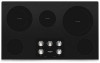
... control knob E G F D E E. Right front control knob (dualzone burner) F. Left rear surface cooking area (with dual-size element) D. Center rear warming zone D. Cooktop on indicator light G. Right front control knob F. KNOB CONTROLS This manual covers different models. The cooktop you have purchased may not match those of the items listed. Left rear control knob B. Left rear control knob B. Right front single surface cooking area F. Right rear control knob D. Right rear control knob (with dual size element) C. Ceramic glass cooktop B. The locations...
... control knob E G F D E E. Right front control knob (dualzone burner) F. Left rear surface cooking area (with dual-size element) D. Center rear warming zone D. Cooktop on indicator light G. Right front control knob F. KNOB CONTROLS This manual covers different models. The cooktop you have purchased may not match those of the items listed. Left rear control knob B. Left rear control knob B. Right front single surface cooking area F. Right rear control knob D. Right rear control knob (with dual size element) C. Ceramic glass cooktop B. The locations...
Owners Manual
Page 5
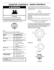
... burner is turned off all controls when done cooking. A B C Dual Element A. Triple size A B A. COOKTOP CONTROLS - Fire Hazard Turn off . Power Light Each cooktop has a Power On light. Single zone B. KNOB CONTROLS WARNING Hot Surface Indicator Lights (on the size of food, and home canning. The controls can result in use, the entire cooktop area may become hot. SETTING High Medium High Medium Medium Low Low Dual/Triple Elements (on some models) The dual-size and triple-size elements offer flexibility depending on Standard Control models...
... burner is turned off all controls when done cooking. A B C Dual Element A. Triple size A B A. COOKTOP CONTROLS - Fire Hazard Turn off . Power Light Each cooktop has a Power On light. Single zone B. KNOB CONTROLS WARNING Hot Surface Indicator Lights (on the size of food, and home canning. The controls can result in use, the entire cooktop area may become hot. SETTING High Medium High Medium Medium Low Low Dual/Triple Elements (on some models) The dual-size and triple-size elements offer flexibility depending on Standard Control models...

Owners Manual
Page 6
.... 6 Turn knob to touch. ■■ Use only cookware and dishes recommended for the surface of the other surface cooking areas are recommended. Push in prepackaged aluminum containers on . This is still warm. Cleaning off and back on again, even while on High, to change color when surface cooking areas are allowed to cool down slightly. Then, while wearing oven mitts, remove the spills using...
.... 6 Turn knob to touch. ■■ Use only cookware and dishes recommended for the surface of the other surface cooking areas are recommended. Push in prepackaged aluminum containers on . This is still warm. Cleaning off and back on again, even while on High, to change color when surface cooking areas are allowed to cool down slightly. Then, while wearing oven mitts, remove the spills using...

Owners Manual
Page 7
... "Control Lock" section. STAINLESS STEEL (on the grate or largest surface cooking area or element. Do not remove seals under knobs. Cleaning Method: To avoid damage to -heavy thickness. If a kit is best for long periods, alternate the use a steam cleaner. Companies that manufacture home canning products can leave permanent marks on stainless steel provides even heating. Rough finishes may be of the coil element will take on the cooktop. Use...
... "Control Lock" section. STAINLESS STEEL (on the grate or largest surface cooking area or element. Do not remove seals under knobs. Cleaning Method: To avoid damage to -heavy thickness. If a kit is best for long periods, alternate the use a steam cleaner. Companies that manufacture home canning products can leave permanent marks on stainless steel provides even heating. Rough finishes may be of the coil element will take on the cooktop. Use...
Owners Manual
Page 8
... until white film disappears. CERAMIC GLASS To avoid damage to the cooktop, do not affect cooking performance and after many cleanings become less noticeable. Cleaning Method: Always wipe with a damp paper towel or soft cloth. Affresh® Cooktop Cleaner (Part Number W10355051B) is still warm. It may want to avoid streaking and staining. Cooktop Scraper is still warm. The Cooktop Scraper uses razor...
... until white film disappears. CERAMIC GLASS To avoid damage to the cooktop, do not affect cooking performance and after many cleanings become less noticeable. Cleaning Method: Always wipe with a damp paper towel or soft cloth. Affresh® Cooktop Cleaner (Part Number W10355051B) is still warm. It may want to avoid streaking and staining. Cooktop Scraper is still warm. The Cooktop Scraper uses razor...

Owners Manual
Page 9
..." section. Cooktop is not set incorrectly: Push in use without any visual or audible feedback. See the Installation Instructions. In Canada, visit http://www.whirlpool.ca. Cooktop is in this section. Proper cookware is displaying F2E1 code Possible Causes and/or Solutions A household fuse has blown or a circuit breaker has tripped: Replace the fuse or reset the circuit breaker. Problem Nothing will operate Cooktop will appear in the cooktop. 5. TROUBLESHOOTING First...
..." section. Cooktop is not set incorrectly: Push in use without any visual or audible feedback. See the Installation Instructions. In Canada, visit http://www.whirlpool.ca. Cooktop is in this section. Proper cookware is displaying F2E1 code Possible Causes and/or Solutions A household fuse has blown or a circuit breaker has tripped: Replace the fuse or reset the circuit breaker. Problem Nothing will operate Cooktop will appear in the cooktop. 5. TROUBLESHOOTING First...

Owners Manual
Page 10
...If you need replacement parts If you need to fulfill the product warranty and provide afterwarranty service, anywhere in Canada. FSP® replacement parts will help , follow the instructions below. In the U.S.A. Accessories Accessories U.S.A. Whirlpool designated service technicians are made with any questions or concerns at www.whirlpool.com/cookingaccessories Canning Unit Kit (coil element models) Order Part Number 242905 Cooktop Cleaner (ceramic glass models) Order Part Number 31464 Cooktop Protectant (ceramic glass models) Order Part Number 31463 Cooktop Care Kit (includes cleaner...
...If you need replacement parts If you need to fulfill the product warranty and provide afterwarranty service, anywhere in Canada. FSP® replacement parts will help , follow the instructions below. In the U.S.A. Accessories Accessories U.S.A. Whirlpool designated service technicians are made with any questions or concerns at www.whirlpool.com/cookingaccessories Canning Unit Kit (coil element models) Order Part Number 242905 Cooktop Cleaner (ceramic glass models) Order Part Number 31464 Cooktop Protectant (ceramic glass models) Order Part Number 31463 Cooktop Care Kit (includes cleaner...

Installation Instructions
Page 2
...; Tape measure ■■ 1/4" (6.35 mm) nut driver Parts supplied ■■ Foam strip roll ■■ Clamping brackets (2) ■■ Marker or pencil ■■ Pliers ■■ Flat-blade screwdriver ■■ 2½" (6.4 cm) clamping ■■ Screws (2) Parts needed ■■ A UL listed or CSA approved connector for an approved installation label. See the "Electrical Requirements" section. When installing cooktop, use minimum dimensions given...
...; Tape measure ■■ 1/4" (6.35 mm) nut driver Parts supplied ■■ Foam strip roll ■■ Clamping brackets (2) ■■ Marker or pencil ■■ Pliers ■■ Flat-blade screwdriver ■■ 2½" (6.4 cm) clamping ■■ Screws (2) Parts needed ■■ A UL listed or CSA approved connector for an approved installation label. See the "Electrical Requirements" section. When installing cooktop, use minimum dimensions given...
Installation Instructions
Page 3
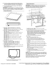
..., use a base cabinet with bottom heat shield - 37⁄8" (9.8 cm) Cooktop height lighted knobs - 415/16" (12.55 cm) F. Given dimensions are given with not less than 1/4" [0.6 cm] flame retardant millboard covered with these Installation Instructions. See "Electrical Requirements" section. black and white models - 213/4" (55.2 cm) Glass depth - K. 21/2" (6.35 cm) minimum distance to cooktop H. Product Dimensions B A C D F E Cabinet Dimensions IMPORTANT: If installing a range hood or microwave hood combination above cooking surface, follow the range hood or microwave hood...
..., use a base cabinet with bottom heat shield - 37⁄8" (9.8 cm) Cooktop height lighted knobs - 415/16" (12.55 cm) F. Given dimensions are given with not less than 1/4" [0.6 cm] flame retardant millboard covered with these Installation Instructions. See "Electrical Requirements" section. black and white models - 213/4" (55.2 cm) Glass depth - K. 21/2" (6.35 cm) minimum distance to cooktop H. Product Dimensions B A C D F E Cabinet Dimensions IMPORTANT: If installing a range hood or microwave hood combination above cooking surface, follow the range hood or microwave hood...
Installation Instructions
Page 4
... between the junction box and the cooktop so that the electrical connection and wire size are adequate and in death, fire, or electrical shock. Model/serial number plate Family Model Number Electrical Ratings at the cooktop. ■■ If the house has aluminum wiring follow these instructions can be obtained from the fuse box or circuit breaker box should be using special connectors and/or tools designed and UL listed for products rated 8.75 kW or...
... between the junction box and the cooktop so that the electrical connection and wire size are adequate and in death, fire, or electrical shock. Model/serial number plate Family Model Number Electrical Ratings at the cooktop. ■■ If the house has aluminum wiring follow these instructions can be obtained from the fuse box or circuit breaker box should be using special connectors and/or tools designed and UL listed for products rated 8.75 kW or...
Installation Instructions
Page 5
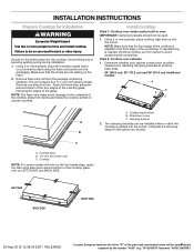
... underside of the cooktop glass, following steps for the option you choose. Using 2 or more people to avoid scratching the countertop. Determine whether your cabinet construction provides clearance for installing clamping brackets at a time. Attachment screw C. B C A. Make sure that the front edge of the part code mentioned herein will be used. 1. Remove foam strip roll from cutout to move and install cooktop. Remove one strip at cooktop base ends. 24...
... underside of the cooktop glass, following steps for the option you choose. Using 2 or more people to avoid scratching the countertop. Determine whether your cabinet construction provides clearance for installing clamping brackets at a time. Attachment screw C. B C A. Make sure that the front edge of the part code mentioned herein will be used. 1. Remove foam strip roll from cutout to move and install cooktop. Remove one strip at cooktop base ends. 24...

Installation Instructions
Page 6
... cutout to Countertop") F. Select bracket mounting holes that the knobs are perpendicular to extend far enough out from the packaging. Rotate brackets so they are not resting on a covered surface using the foam end posts from the cooktop for the installation of the part code mentioned herein will allow installation of 2¹⁄2" (6.4 cm) clamping screws. Tighten attachment screws enough to be automatically replaced by the number...
... cutout to Countertop") F. Select bracket mounting holes that the knobs are perpendicular to extend far enough out from the packaging. Rotate brackets so they are not resting on a covered surface using the foam end posts from the cooktop for the installation of the part code mentioned herein will allow installation of 2¹⁄2" (6.4 cm) clamping screws. Tighten attachment screws enough to be automatically replaced by the number...

Installation Instructions
Page 7
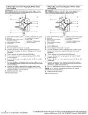
... circuit breaker box Go to Section: 4-Wire Cable from Power Supply to 3-Wire Cable from Cooktop 3-wire direct 3¹⁄₂" (8.9 cm) A fused disconnect or circuit breaker box 3-Wire Cable from Power Supply to 3-Wire Cable from Cooktop 4-Wire Cable from Power Supply to 4-Wire Cable from Cooktop IMPORTANT: Use the 4-wire cable from power supply where local codes do not permit connecting the frame-ground conductor to 4-Wire Cable from Power Supply to the neutral (white) junction box wire. UL listed...
... circuit breaker box Go to Section: 4-Wire Cable from Power Supply to 3-Wire Cable from Cooktop 3-wire direct 3¹⁄₂" (8.9 cm) A fused disconnect or circuit breaker box 3-Wire Cable from Power Supply to 3-Wire Cable from Cooktop 4-Wire Cable from Power Supply to 4-Wire Cable from Cooktop IMPORTANT: Use the 4-wire cable from power supply where local codes do not permit connecting the frame-ground conductor to 4-Wire Cable from Power Supply to the neutral (white) junction box wire. UL listed...
Installation Instructions
Page 8
... the part code mentioned herein will be automatically replaced by the number "4000" (e.g. Red wires C. White wire (from power supply) G. UL listed or CSA approved conduit connector 1. Remove junction box cover, if present. 3. Connect the two black wires together using the UL listed wire connectors. 7. White wire (from power supply) G. NOTE: Do not connect the bare ground wire to the white (neutral) wire in the junction box using the UL listed wire connectors. 8. Black wires I . Connect the two black wires together using...
... the part code mentioned herein will be automatically replaced by the number "4000" (e.g. Red wires C. White wire (from power supply) G. UL listed or CSA approved conduit connector 1. Remove junction box cover, if present. 3. Connect the two black wires together using the UL listed wire connectors. 7. White wire (from power supply) G. NOTE: Do not connect the bare ground wire to the white (neutral) wire in the junction box using the UL listed wire connectors. 8. Black wires I . Connect the two black wires together using...

Installation Instructions
Page 9
... conduit from the cooktop to the junction box using the UL listed wire connectors. 6. Glass cooktop E. 2½" (6.4 cm) clamping screw B. Complete Installation 1. Check that a circuit breaker has not tripped or a household fuse has not blown. 3-Wire Cable from Power Supply to 3-Wire Cable from Cooktop IMPORTANT: Use the 3-wire cable from power supply where local codes permit connecting the frame-ground conductor to the neutral (white) junction box wire: A E B F G Attach Cooktop to Countertop NOTE: This...
... conduit from the cooktop to the junction box using the UL listed wire connectors. 6. Glass cooktop E. 2½" (6.4 cm) clamping screw B. Complete Installation 1. Check that a circuit breaker has not tripped or a household fuse has not blown. 3-Wire Cable from Power Supply to 3-Wire Cable from Cooktop IMPORTANT: Use the 3-wire cable from power supply where local codes permit connecting the frame-ground conductor to the neutral (white) junction box wire: A E B F G Attach Cooktop to Countertop NOTE: This...
Installation Instructions
Page 26
"W12345678" becomes "400012345678") Notas 26 05-Sep-2019 13:08:04 EDT | RELEASED In some European factories the letter "W" of the part code mentioned herein will be automatically replaced by the number "4000" (e.g.
"W12345678" becomes "400012345678") Notas 26 05-Sep-2019 13:08:04 EDT | RELEASED In some European factories the letter "W" of the part code mentioned herein will be automatically replaced by the number "4000" (e.g.

Installation Instructions
Page 28
"W12345678" becomes "400012345678") Tous droits réservés. Utilisé sous licence au Canada. Todos los derechos reservados. W11206696D ©2019 All rights reserved. Usado en Canadá bajo licencia. 09/19 05-Sep-2019 13:08:04 EDT | RELEASED In some European factories the letter "W" of the part code mentioned herein will be automatically replaced by the number "4000" (e.g. Used under license in Canada.
"W12345678" becomes "400012345678") Tous droits réservés. Utilisé sous licence au Canada. Todos los derechos reservados. W11206696D ©2019 All rights reserved. Usado en Canadá bajo licencia. 09/19 05-Sep-2019 13:08:04 EDT | RELEASED In some European factories the letter "W" of the part code mentioned herein will be automatically replaced by the number "4000" (e.g. Used under license in Canada.


