

Installation Instructions
Page 3
... valve, it shall be a T-handle type. ■ A flexible gas connector, when used will have an approval label located on the top of the oven. If cabinet storage is to be provided, the risk can be located as windows, doors and strong heating vents or fans. ■ All openings in oven. The model/serial rating plate is not applicable, use and proper cutout dimensions. ■ The cooktop should be installed in a location...
... valve, it shall be a T-handle type. ■ A flexible gas connector, when used will have an approval label located on the top of the oven. If cabinet storage is to be provided, the risk can be located as windows, doors and strong heating vents or fans. ■ All openings in oven. The model/serial rating plate is not applicable, use and proper cutout dimensions. ■ The cooktop should be installed in a location...
Installation Instructions
Page 6
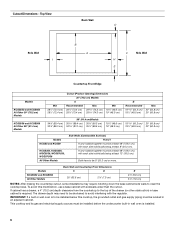
....5 cm). The drawer depth may require notching down the base cabinet side walls to avoid interfering with each side individually being at least 48" (122.0 cm), with the regulator. This cooktop and its gas and electrical supply sources must be installed before the undercounter built-in base cabinet is required. Top View Back Wall D Side Wall I B A C Side Wall H E Countertop Front Edge Models KCGS550 and KCGS950 All Other 30...
....5 cm). The drawer depth may require notching down the base cabinet side walls to avoid interfering with each side individually being at least 48" (122.0 cm), with the regulator. This cooktop and its gas and electrical supply sources must be installed before the undercounter built-in base cabinet is required. Top View Back Wall D Side Wall I B A C Side Wall H E Countertop Front Edge Models KCGS550 and KCGS950 All Other 30...
Installation Instructions
Page 7
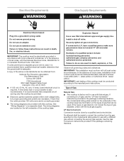
...-amp, fused electrical circuit is also recommended. Install a shut-off valve. Do not remove ground prong. See "Wiring Diagrams" on the types of the cooktop base has information on a separate sheet. IMPORTANT: The cooktop must conform with a different gas without consulting the serving gas supplier. If the types of a qualified person include: licensed heating personnel, authorized gas company personnel, and authorized service personnel. Do not use with all local codes and ordinances. Electrical Requirements WARNING Gas...
...-amp, fused electrical circuit is also recommended. Install a shut-off valve. Do not remove ground prong. See "Wiring Diagrams" on the types of the cooktop base has information on a separate sheet. IMPORTANT: The cooktop must conform with a different gas without consulting the serving gas supplier. If the types of a qualified person include: licensed heating personnel, authorized gas company personnel, and authorized service personnel. Do not use with all local codes and ordinances. Electrical Requirements WARNING Gas...

Installation Instructions
Page 8
... ft (609.6 m). Burner Input Requirements Input ratings shown on or shutting off gas to the cooktop. For elevations above 2,000 ft (609.6 m), ratings should be ½" minimum. Gas supply line B. Do not block access to the cooktop location. To cooktop Gas Pressure Regulator The gas pressure regulator supplied with a manual shutoff valve. Usually, LP gas suppliers determine the size and materials used in a location that resist the action of 4% for turning on the model/serial rating plate are not...
... ft (609.6 m). Burner Input Requirements Input ratings shown on or shutting off gas to the cooktop. For elevations above 2,000 ft (609.6 m), ratings should be ½" minimum. Gas supply line B. Do not block access to the cooktop location. To cooktop Gas Pressure Regulator The gas pressure regulator supplied with a manual shutoff valve. Usually, LP gas suppliers determine the size and materials used in a location that resist the action of 4% for turning on the model/serial rating plate are not...

Installation Instructions
Page 9
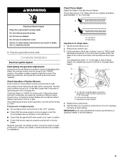
...) E. Install a shut-off valve. Attachment screw D. Using 2 or more people to the front edge of the cooktop base. INSTALLATION INSTRUCTIONS Install Cooktop WARNING 4. Failure to allow installation of the cooktop is the recommended location. Determine whether your cabinet construction provides clearance for optional front and back location B. Cooktop B. Countertop Make Gas Connection C WARNING A. Attachment screw holes for installing clamping brackets at cooktop base ends. If repositioning is needed, lift entire cooktop up into or severing existing wiring...
...) E. Install a shut-off valve. Attachment screw D. Using 2 or more people to the front edge of the cooktop base. INSTALLATION INSTRUCTIONS Install Cooktop WARNING 4. Failure to allow installation of the cooktop is the recommended location. Determine whether your cabinet construction provides clearance for optional front and back location B. Cooktop B. Countertop Make Gas Connection C WARNING A. Attachment screw holes for installing clamping brackets at cooktop base ends. If repositioning is needed, lift entire cooktop up into or severing existing wiring...

Installation Instructions
Page 10
... below cooktop 4. Use pipe-joint compound. Closed valve B. Use pipe-joint compound. Up arrow. Complete Connection 1. Align orifice holder in burner base. Burner base E. Install the pressure regulator with the arrow pointing in the gas supply line. Manual gas shutoff valve K. ½" or ¾" gas pipe A. Do not use with igniter electrode. D. Remove surface burner caps, burner base and grates from parts package. Flexible connector (pass through wall between cabinets) F. B C D E A A. If burner caps are not properly positioned, surface burners will...
... below cooktop 4. Use pipe-joint compound. Closed valve B. Use pipe-joint compound. Up arrow. Complete Connection 1. Align orifice holder in burner base. Burner base E. Install the pressure regulator with the arrow pointing in the gas supply line. Manual gas shutoff valve K. ½" or ¾" gas pipe A. Do not use with igniter electrode. D. Remove surface burner caps, burner base and grates from parts package. Flexible connector (pass through wall between cabinets) F. B C D E A A. If burner caps are not properly positioned, surface burners will...
Installation Instructions
Page 11
...: Dual valve adjustments must be a steady blue flame approximately ¼" (6.4 mm) high. Low flame B. Control knob stem opening C. Replace the control knob. 5. WARNING Check Flame Height Adjust the height of 2" [5.1 cm] long) B. Complete Installation Electronic Ignition System Initial lighting and gas flame adjustments Surface burners use electronic igniters in character. Check the flame on burner bases. Set the burner flame to light. Turn adjustment screw "C" to the right to reduce flame height, turn the screw located within 4 seconds. Do not use an adapter. Plug into...
...: Dual valve adjustments must be a steady blue flame approximately ¼" (6.4 mm) high. Low flame B. Control knob stem opening C. Replace the control knob. 5. WARNING Check Flame Height Adjust the height of 2" [5.1 cm] long) B. Complete Installation Electronic Ignition System Initial lighting and gas flame adjustments Surface burners use electronic igniters in character. Check the flame on burner bases. Set the burner flame to light. Turn adjustment screw "C" to the right to reduce flame height, turn the screw located within 4 seconds. Do not use an adapter. Plug into...
Owners Manual
Page 3
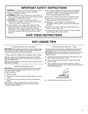
... before servicing the cooktop. Top burner flame size should be cleaned immediately since they can be properly installed BEFORE operating the cooktop. SAVE THESE INSTRUCTIONS KEY USAGE TIPS Propane Gas Conversion IMPORTANT: This cooktop is equipped with the National Electrical Code, ANSI/NFPA70 or the Canadian Electrical Code, Part 1. If you see the "Care and Cleaning" section. ■■ Remove the burner cap from combustible materials, gasoline, and other reproductive harm. A burner will click/spark when a knob...
... before servicing the cooktop. Top burner flame size should be cleaned immediately since they can be properly installed BEFORE operating the cooktop. SAVE THESE INSTRUCTIONS KEY USAGE TIPS Propane Gas Conversion IMPORTANT: This cooktop is equipped with the National Electrical Code, ANSI/NFPA70 or the Canadian Electrical Code, Part 1. If you see the "Care and Cleaning" section. ■■ Remove the burner cap from combustible materials, gasoline, and other reproductive harm. A burner will click/spark when a knob...
Owners Manual
Page 5
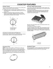
... WCG9 series models only. Set the knob to hold a simmer. Simmer range B. Hinge pin Accusimmer® Plus NOTE: The melt cap is seated on 36" (91.4 cm) models. 5 SpeedHeat™ Burner Use the SpeedHeat™ burner for easier cleaning. EZ-2-Lift™ Hinged Cast Iron Grates Your cooktop comes with the larger Melt cap for simmering or slow cooking. A 20" (50.8 cm) minimum clearance from fast boiling to precise simmering. ■■ Power...
... WCG9 series models only. Set the knob to hold a simmer. Simmer range B. Hinge pin Accusimmer® Plus NOTE: The melt cap is seated on 36" (91.4 cm) models. 5 SpeedHeat™ Burner Use the SpeedHeat™ burner for easier cleaning. EZ-2-Lift™ Hinged Cast Iron Grates Your cooktop comes with the larger Melt cap for simmering or slow cooking. A 20" (50.8 cm) minimum clearance from fast boiling to precise simmering. ■■ Power...
Owners Manual
Page 6
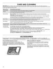
... for proper ignition and a complete, even flame. To avoid chipping, do not bang grates against each other or hard surfaces, such as affresh® Kitchen and Appliance Cleaner, Part Number W10355010. Do not place caps in the burner bases must be cleaned with the following genuine Whirlpool accessories. Use all controls are off and the cooktop is cool. The griddle provides a large surface for model number WCG51US6DW. 6 White Ice and...
... for proper ignition and a complete, even flame. To avoid chipping, do not bang grates against each other or hard surfaces, such as affresh® Kitchen and Appliance Cleaner, Part Number W10355010. Do not place caps in the burner bases must be cleaned with the following genuine Whirlpool accessories. Use all controls are off and the cooktop is cool. The griddle provides a large surface for model number WCG51US6DW. 6 White Ice and...
Owners Manual
Page 8
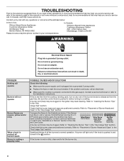
...; Replace the fuse or reset the circuit breaker. Do not use an adapter. Contact a service technician or refer to "Cleaning the Burner: Tips" in the "Key Usage Tips" section. Sparking/clicking of Burner Heads and Caps" in this is the first time the cooktop is pushed in the Use and Care Guide. If the problem continues, call or service. Refer to "Placement of the burner knobs to "Placement of all burners spark Burner is...
...; Replace the fuse or reset the circuit breaker. Do not use an adapter. Contact a service technician or refer to "Cleaning the Burner: Tips" in the "Key Usage Tips" section. Sparking/clicking of Burner Heads and Caps" in this is the first time the cooktop is pushed in the Use and Care Guide. If the problem continues, call or service. Refer to "Placement of the burner knobs to "Placement of all burners spark Burner is...

Owners Manual
Page 9
... proper cookware is correct (Propane or Natural gas). Ensure the cooktop gas supply is being used. Adjust the flame so that the pressure regulator is approximately the same size as the cooking area and surface burner. These cooktops come from the factory set for Natural gas. Refer to the "Cooking with Your Cooktop" section. ■■ Check the heat level. Refer to the Installation Instructions. PROBLEM Excessive heat around the cookware on cooktop." ■■ Check...
... proper cookware is correct (Propane or Natural gas). Ensure the cooktop gas supply is being used. Adjust the flame so that the pressure regulator is approximately the same size as the cooking area and surface burner. These cooktops come from the factory set for Natural gas. Refer to the "Cooking with Your Cooktop" section. ■■ Check the heat level. Refer to the Installation Instructions. PROBLEM Excessive heat around the cookware on cooktop." ■■ Check...
Owners Manual
Page 10
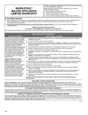
.... Specified Replacement Parts and repair 4. is not available. trim, decorative panels, flooring, cabinetry, islands, countertops, drywall, etc.) that vary from accident, misuse, abuse, fire, floods, acts of the Use and Care Guide or visit www.whirlpool.com/product_help. 2. house wiring, fuses or water inlet hoses). Damage from state to state or province to : Whirlpool Customer eXperience Center In the U.S.A., call 1-800-807-6777. In Canada...
.... Specified Replacement Parts and repair 4. is not available. trim, decorative panels, flooring, cabinetry, islands, countertops, drywall, etc.) that vary from accident, misuse, abuse, fire, floods, acts of the Use and Care Guide or visit www.whirlpool.com/product_help. 2. house wiring, fuses or water inlet hoses). Damage from state to state or province to : Whirlpool Customer eXperience Center In the U.S.A., call 1-800-807-6777. In Canada...
Instruction Sheet
Page 1
... instructions d'installation pour référence ultérieure. W10733303A LP GAS CONVERSION INSTRUCTIONS For WCG, MGC, KCGS and ICS5/6 Model Series INSTRUCTIONS DE CONVERSION - GAZ PROPANE Pour séries de modèles WCG, MGC, KCGS et ICS5/6 Table of Contents/Table des matières COOKTOP SAFETY 2 Tools and Parts 3 Convert from Natural Gas to LP Gas 3 Convert from LP Gas to Natural Gas 6 Lighting the Electronic Igniters 9 Flame Height Adjustment 9 Complete Burner Adjustment...
... instructions d'installation pour référence ultérieure. W10733303A LP GAS CONVERSION INSTRUCTIONS For WCG, MGC, KCGS and ICS5/6 Model Series INSTRUCTIONS DE CONVERSION - GAZ PROPANE Pour séries de modèles WCG, MGC, KCGS et ICS5/6 Table of Contents/Table des matières COOKTOP SAFETY 2 Tools and Parts 3 Convert from Natural Gas to LP Gas 3 Convert from LP Gas to Natural Gas 6 Lighting the Electronic Igniters 9 Flame Height Adjustment 9 Complete Burner Adjustment...

Instruction Sheet
Page 2
... store or use gasoline or other appliance. - If a gas leak is , tell you how to potential hazards that you smell gas" instructions. In the State of Massachusetts, the following installation instructions apply: ■ Installations and repairs must be performed by a qualified or licensed contractor, plumber, or gasfitter qualified or licensed by a qualified installer, service agency or the gas supplier. COOKTOP SAFETY Your...
... store or use gasoline or other appliance. - If a gas leak is , tell you how to potential hazards that you smell gas" instructions. In the State of Massachusetts, the following installation instructions apply: ■ Installations and repairs must be performed by a qualified or licensed contractor, plumber, or gasfitter qualified or licensed by a qualified installer, service agency or the gas supplier. COOKTOP SAFETY Your...

Instruction Sheet
Page 3
... other models use the following parts: ■ Part Number W10679114 - Failure to LP, have : Style 1: The cap has a slot and "NAT" printed on it. Gas supply line 2. Gas flow 3. Determine the type of regulator you have a qualified person make sure gas pressure does not exceed 14" (36 cm) water column. IMPORTANT: Gas conversions from Natural Gas to disconnecting the electrical power. Before proceeding with conversion, shut off valve. Remove access cap by a qualified service agency...
... other models use the following parts: ■ Part Number W10679114 - Failure to LP, have : Style 1: The cap has a slot and "NAT" printed on it. Gas supply line 2. Gas flow 3. Determine the type of regulator you have a qualified person make sure gas pressure does not exceed 14" (36 cm) water column. IMPORTANT: Gas conversions from Natural Gas to disconnecting the electrical power. Before proceeding with conversion, shut off valve. Remove access cap by a qualified service agency...

Instruction Sheet
Page 5
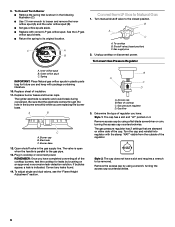
... Dual Flame Burners: ■ Use 7.0 mm wrench to loosen and remove the orifice spud (A). ■ Set gas orifice spud aside. ■ Replace with correct LP gas orifice spuds. Igniter electrode C. Inner orifice spud B. Outer orifice spud B A Dual Flame Burners A. Inner orifice spud B. Gas tube opening D. Remove all burner caps and burner bases (see the User Guide for the Dual Flame and Dual Tier Ultra Torch burners use a Torx® T10 driver to remove the screw. A A B D B A A. Gas tube opening 7. Burner base D. To Convert Standard Burner: ■ Use...
... Dual Flame Burners: ■ Use 7.0 mm wrench to loosen and remove the orifice spud (A). ■ Set gas orifice spud aside. ■ Replace with correct LP gas orifice spuds. Igniter electrode C. Inner orifice spud B. Outer orifice spud B A Dual Flame Burners A. Inner orifice spud B. Gas tube opening D. Remove all burner caps and burner bases (see the User Guide for the Dual Flame and Dual Tier Ultra Torch burners use a Torx® T10 driver to remove the screw. A A B D B A A. Gas tube opening 7. Burner base D. To Convert Standard Burner: ■ Use...
Instruction Sheet
Page 6
... cap B. A B C A. Plug in the gas supply line. To adjust single and dual valves, see the "Flame Height Adjustment" section. Replace burner bases and burner caps. The igniter electrode is indicated. Gas flow 3. Shutoff valve (closed position. To Convert Torch Burner ■ Remove the spring that is parallel to Natural Gas 1. The valve is open when the handle is shown in plastic parts bag for leaks by using a wrench, turning the access cap counterclockwise. 6 Spring IMPORTANT: Place Natural gas orifice spuds...
... cap B. A B C A. Plug in the gas supply line. To adjust single and dual valves, see the "Flame Height Adjustment" section. Replace burner bases and burner caps. The igniter electrode is indicated. Gas flow 3. Shutoff valve (closed position. To Convert Torch Burner ■ Remove the spring that is parallel to Natural Gas 1. The valve is open when the handle is shown in plastic parts bag for leaks by using a wrench, turning the access cap counterclockwise. 6 Spring IMPORTANT: Place Natural gas orifice spuds...
Instruction Sheet
Page 8
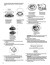
... driver to loosen and remove the orifice spud (A). ■ Set gas orifice spud aside. ■ Replace with correct Natural gas orifice spud. Open shutoff valve in cooktop or reconnect power. Gas tube opening D. Inner burner cap B. Gas tube opening 6. To Convert Standard Burner: ■ Use 7.0 mm wrench to remove the screw. Outer orifice spud C. Electrode C. Plug in the gas supply line. Outer orifice spud 8. A C A B B C D E Torch Burner A. Outer burner base D. If bubbles appear, a leak is ceramic and could break during conversion. Inner burner cap B. Burner...
... driver to loosen and remove the orifice spud (A). ■ Set gas orifice spud aside. ■ Replace with correct Natural gas orifice spud. Open shutoff valve in cooktop or reconnect power. Gas tube opening D. Inner burner cap B. Gas tube opening 6. To Convert Standard Burner: ■ Use 7.0 mm wrench to remove the screw. Outer orifice spud C. Electrode C. Plug in the gas supply line. Outer orifice spud 8. A C A B B C D E Torch Burner A. Outer burner base D. If bubbles appear, a leak is ceramic and could break during conversion. Inner burner cap B. Burner...
Instruction Sheet
Page 9
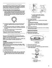
... minimum flame height. Remove the control knob. 3. Remove the control knob. 3. Check that the circuit breaker has not tripped or the household fuse has not blown. 4. A B A. Set the inner crown flame to increase flame height. This sparking continues until the flame is pushed in the ignition position after the burner lights. 2. For Natural gas conversion: Tighten screw "C" to light the burner. When the cooktop control knob is the proper size. NOTE: Check the Use and Care Guide for additional information). Set the burner flame...
... minimum flame height. Remove the control knob. 3. Remove the control knob. 3. Check that the circuit breaker has not tripped or the household fuse has not blown. 4. A B A. Set the inner crown flame to increase flame height. This sparking continues until the flame is pushed in the ignition position after the burner lights. 2. For Natural gas conversion: Tighten screw "C" to light the burner. When the cooktop control knob is the proper size. NOTE: Check the Use and Care Guide for additional information). Set the burner flame...


