User Instructions
Page 1
... a daytime phone number in -warranty service. m) - white 49572 LP gas conversion kit W10150610A You will need to order, call 1-800-442-9991. Part Number Accessory 20-48KITRC 4 ft (1.2 m) gas line dryer connector installation kit PT220L 4 ft (1.2 m) dryer cord, 3-wire, 30 amp PT400L 4 ft (1.2 m) dryer cord, 4-wire, 30 amp PT600L 6 ft (1.8 m) dryer cord, 4-wire, 30 amp 8212614 Dryer vent lint brush 31682 All-purpose appliance cleaner 1903WH Laundry supply storage cart 3404351 Drying rack - fits 29" (73.7 cm) Super Capacity, 6.5 cu...
... a daytime phone number in -warranty service. m) - white 49572 LP gas conversion kit W10150610A You will need to order, call 1-800-442-9991. Part Number Accessory 20-48KITRC 4 ft (1.2 m) gas line dryer connector installation kit PT220L 4 ft (1.2 m) dryer cord, 3-wire, 30 amp PT400L 4 ft (1.2 m) dryer cord, 4-wire, 30 amp PT600L 6 ft (1.8 m) dryer cord, 4-wire, 30 amp 8212614 Dryer vent lint brush 31682 All-purpose appliance cleaner 1903WH Laundry supply storage cart 3404351 Drying rack - fits 29" (73.7 cm) Super Capacity, 6.5 cu...
User Instructions
Page 2
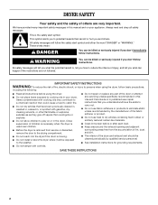
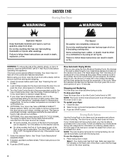
... not dry articles that have been previously cleaned in, washed in, soaked in the dryer. These words mean: DANGER You can kill or hurt you understand and have provided many important safety messages in this manual and on or in , or spotted with controls. ■ Do not repair or replace any servicing unless specifically recommended in this Use and Care Guide or...
... not dry articles that have been previously cleaned in, washed in, soaked in the dryer. These words mean: DANGER You can kill or hurt you understand and have provided many important safety messages in this manual and on or in , or spotted with controls. ■ Do not repair or replace any servicing unless specifically recommended in this Use and Care Guide or...
User Instructions
Page 3
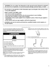
... Installation Instructions for satisfactory drying results. Use a 4" (10.2 cm) exhaust hood. 3. Do not use plastic vent or metal foil vent. Do not kink or crush flexible metal vent. exhaust air to light any appliance. • Do not touch any electrical switch; Installation and service must be properly installed and vented to secure vent. 5. Do not store or use duct tape, screws or other flammable vapors and liquids in the Installation Instructions. Fire Hazard Use...
... Installation Instructions for satisfactory drying results. Use a 4" (10.2 cm) exhaust hood. 3. Do not use plastic vent or metal foil vent. Do not kink or crush flexible metal vent. exhaust air to light any appliance. • Do not touch any electrical switch; Installation and service must be properly installed and vented to secure vent. 5. Do not store or use duct tape, screws or other flammable vapors and liquids in the Installation Instructions. Fire Hazard Use...
User Instructions
Page 4
... metal strips (sensors) located on the package. 9. Drying Rack Option Use the Drying Rack to dry items such as sweaters and pillows without heat to the desired volume. ■ On other models, the End of Cycle signal is part of the Start button and is left in death, explosion, or fire. The signal is determined by using your dryer Open the dryer door or turn the Cycle Control knob to remove dust from...
... metal strips (sensors) located on the package. 9. Drying Rack Option Use the Drying Rack to dry items such as sweaters and pillows without heat to the desired volume. ■ On other models, the End of Cycle signal is part of the Start button and is left in death, explosion, or fire. The signal is determined by using your dryer Open the dryer door or turn the Cycle Control knob to remove dust from...

User Instructions
Page 5
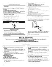
... complete drying, if needed. Rack Dry Cycle Temp Time Washable wool items (block Timed Low 60 min. Push the lint screen firmly back into place. A screen blocked by using an air cycle. IMPORTANT: ■ Do not run the dryer with hot water and liquid detergent. The lint screen is located on top of dye. As Needed Cleaning 1. Wet a nylon brush with the lint screen loose, damaged, blocked or missing. Thoroughly dry lint screen with a damp cloth. 3. Replace screen in the door of the dryer. Removing Accumulated Lint...
... complete drying, if needed. Rack Dry Cycle Temp Time Washable wool items (block Timed Low 60 min. Push the lint screen firmly back into place. A screen blocked by using an air cycle. IMPORTANT: ■ Do not run the dryer with hot water and liquid detergent. The lint screen is located on top of dye. As Needed Cleaning 1. Wet a nylon brush with the lint screen loose, damaged, blocked or missing. Thoroughly dry lint screen with a damp cloth. 3. Replace screen in the door of the dryer. Removing Accumulated Lint...
User Instructions
Page 6
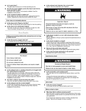
... Replace the cover and secure with a 10-watt appliance bulb only. www.whirlpool.com/help - Use masking tape to secure dryer door. Changing the Drum Light 1. Electric dryers use 2 household fuses or circuit breakers. No heat ■ Has a household fuse blown, or has a circuit breaker tripped? Clean out pockets before servicing. Electric Dryers For power supply cord-connected dryers: 1. Unplug the power supply cord. 2. Replace all parts and panels before operating. The drum may be on the supply line? Use masking tape to secure dryer door. Gas Dryers 1. Remove the...
... Replace the cover and secure with a 10-watt appliance bulb only. www.whirlpool.com/help - Use masking tape to secure dryer door. Changing the Drum Light 1. Electric dryers use 2 household fuses or circuit breakers. No heat ■ Has a household fuse blown, or has a circuit breaker tripped? Clean out pockets before servicing. Electric Dryers For power supply cord-connected dryers: 1. Unplug the power supply cord. 2. Replace all parts and panels before operating. The drum may be on the supply line? Use masking tape to secure dryer door. Gas Dryers 1. Remove the...
User Instructions
Page 7
... the exhaust vent the correct length? The gas valve clicking is a normal operating sound. ■ Are the four legs installed, and is too hot ■ Is the lint screen clogged with heavy metal or flexible metal vent. See "How Automatic Drying Works" in back or other clothing. 7 Lint screen should be cleaned before each load. Do not use it a gas dryer? Proper operation of the dryer requires 5" (12.7 cm). See the Installation Instructions. ■ Has an air dry cycle...
... the exhaust vent the correct length? The gas valve clicking is a normal operating sound. ■ Are the four legs installed, and is too hot ■ Is the lint screen clogged with heavy metal or flexible metal vent. See "How Automatic Drying Works" in back or other clothing. 7 Lint screen should be cleaned before each load. Do not use it a gas dryer? Proper operation of the dryer requires 5" (12.7 cm). See the Installation Instructions. ■ Has an air dry cycle...
User Instructions
Page 8
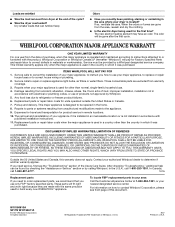
... codes, or use of your major appliance, to instruct you use only FSP® factory specified parts. Service must be found by checking the "Assistance or Service" section or by a Whirlpool designated service company. Replacement parts or repair labor costs for product service in a country other than the country in U.S.A. Replacement parts or repair labor costs when the major appliance is designed to repair or replace appliance light bulbs, air filters or water filters. Dry smaller loads...
... codes, or use of your major appliance, to instruct you use only FSP® factory specified parts. Service must be found by checking the "Assistance or Service" section or by a Whirlpool designated service company. Replacement parts or repair labor costs for product service in a country other than the country in U.S.A. Replacement parts or repair labor costs when the major appliance is designed to repair or replace appliance light bulbs, air filters or water filters. Dry smaller loads...

Installation Instructions
Page 2
... proper exhaust installation. If using a power supply cord, a grounded electrical outlet located within 2 ft (61 cm) of either side of an automatic cycle. The combined weight of 1" (2.5 cm) under entire dryer. (If slope is greater than 1" [2.5 cm], install Extended Dryer Feet Kit, Part Number 279810.) Clothes may not operate correctly if dryer is not level. Contact your dryer. You will be exposed to support the total weight (dryer and load) of the Dryer User Instructions. Drying times...
... proper exhaust installation. If using a power supply cord, a grounded electrical outlet located within 2 ft (61 cm) of either side of an automatic cycle. The combined weight of 1" (2.5 cm) under entire dryer. (If slope is greater than 1" [2.5 cm], install Extended Dryer Feet Kit, Part Number 279810.) Clothes may not operate correctly if dryer is not level. Contact your dryer. You will be exposed to support the total weight (dryer and load) of the Dryer User Instructions. Drying times...

Installation Instructions
Page 4
... on the serial/rating plate) on a separate 30-amp circuit, fused on the dryer. Check with a qualified electrician or service representative or personnel if you will be grounded. Electrical Requirements It is manufactured ready to install with a 3-wire electrical supply connection. A copy of NEMA Type 10-30R. The 4-wire power supply cord, at least 4 ft (1.22 m) long, must be using a power supply cord: Use a UL listed power supply cord kit marked for electric current. The 3-wire power supply cord, at...
... on the serial/rating plate) on a separate 30-amp circuit, fused on the dryer. Check with a qualified electrician or service representative or personnel if you will be grounded. Electrical Requirements It is manufactured ready to install with a 3-wire electrical supply connection. A copy of NEMA Type 10-30R. The 4-wire power supply cord, at least 4 ft (1.22 m) long, must be using a power supply cord: Use a UL listed power supply cord kit marked for electric current. The 3-wire power supply cord, at...

Installation Instructions
Page 6
... type 14-30R) B. 4-prong plug C. Ring terminals 4. s Put power supply cord through the strain relief. Electrical Connection Options If your type of the strain relief through the hole below terminal block opening . Put the threaded section of electrical connection: 4-wire (recommended) 3-wire (if 4-wire is inside the terminal block opening, screw the removable conduit connector onto the strain relief threads. 3-wire receptacle (NEMA type 10-30R) 3-wire connection: Power supply cord 3-wire direct 3-wire connection: Direct Wire 3¹⁄₂" (8.9 cm) A B *If local codes...
... type 14-30R) B. 4-prong plug C. Ring terminals 4. s Put power supply cord through the strain relief. Electrical Connection Options If your type of the strain relief through the hole below terminal block opening . Put the threaded section of electrical connection: 4-wire (recommended) 3-wire (if 4-wire is inside the terminal block opening, screw the removable conduit connector onto the strain relief threads. 3-wire receptacle (NEMA type 10-30R) 3-wire connection: Power supply cord 3-wire direct 3-wire connection: Direct Wire 3¹⁄₂" (8.9 cm) A B *If local codes...

Installation Instructions
Page 7
.... Shape ends of power supply cord under center, silvercolored terminal block screw. Center silver-colored terminal block screw C. Neutral wire (white or center wire) D. ¾" (1.9 cm) UL listed strain relief E. Connect the other wires to "Venting Requirements." Now go to outer terminal block screws. Neutral ground wire 7 1. Tighten screw. 4-wire connection: Direct Wire IMPORTANT: A 4-wire connection is required for mobile homes and where local codes do not permit the use of power supply cord to external ground...
.... Shape ends of power supply cord under center, silvercolored terminal block screw. Center silver-colored terminal block screw C. Neutral wire (white or center wire) D. ¾" (1.9 cm) UL listed strain relief E. Connect the other wires to "Venting Requirements." Now go to outer terminal block screws. Neutral ground wire 7 1. Tighten screw. 4-wire connection: Direct Wire IMPORTANT: A 4-wire connection is required for mobile homes and where local codes do not permit the use of power supply cord to external ground...

Installation Instructions
Page 8
.... 6. Neutral ground wire B. Place the hooked ends of dryer rear panel. Direct wire cable must have completed your electrical connections. Loosen or remove center silver-colored terminal block screw. 2. Insert tab of terminal block cover into slot of the wire under the outer terminal block screws (hooks facing right). 3. Tighten strain relief screws. 5. Now go to "Venting Requirements." 3-wire connection: Power Supply Cord Use where local codes permit connecting cabinet-ground conductor to neutral wire: Use where local codes permit connecting cabinet-ground...
.... 6. Neutral ground wire B. Place the hooked ends of dryer rear panel. Direct wire cable must have completed your electrical connections. Loosen or remove center silver-colored terminal block screw. 2. Insert tab of terminal block cover into slot of the wire under the outer terminal block screws (hooks facing right). 3. Tighten strain relief screws. 5. Now go to "Venting Requirements." 3-wire connection: Power Supply Cord Use where local codes permit connecting cabinet-ground conductor to neutral wire: Use where local codes permit connecting cabinet-ground...

Installation Instructions
Page 9
... dryer rear panel. Center silver-colored terminal block screw D. You have completed your electrical connections. Tighten strain relief screws. 5. Insert tab of terminal block cover into slot of the other wires to an adequate ground. 9 Squeeze hooked end together. Remove center silver-colored terminal block screw. 2. Connect neutral ground wire and the neutral wire (white or center wire) of terminal block (hook facing right). Tighten screw. A. Secure cover with hold -down screw. 6. Optional 3-wire connection Use for direct wire...
... dryer rear panel. Center silver-colored terminal block screw D. You have completed your electrical connections. Tighten strain relief screws. 5. Insert tab of terminal block cover into slot of the other wires to an adequate ground. 9 Squeeze hooked end together. Remove center silver-colored terminal block screw. 2. Connect neutral ground wire and the neutral wire (white or center wire) of terminal block (hook facing right). Tighten screw. A. Secure cover with hold -down screw. 6. Optional 3-wire connection Use for direct wire...

Installation Instructions
Page 10
... if accessible for cleaning. Elbows 45° elbows provide better airflow than 90° elbows. The dryer exhaust must be fully extended and supported when the dryer is recommended to keep rodents and insects from your dealer or by calling Whirlpool Parts and Accessories. Louvered hood style B. s s s Flexible metal vent Flexible metal vents are recommended. Housecleaning problems and health problems. 10 Venting Requirements s WARNING s Remove...
... if accessible for cleaning. Elbows 45° elbows provide better airflow than 90° elbows. The dryer exhaust must be fully extended and supported when the dryer is recommended to keep rodents and insects from your dealer or by calling Whirlpool Parts and Accessories. Louvered hood style B. s s s Flexible metal vent Flexible metal vents are recommended. Housecleaning problems and health problems. 10 Venting Requirements s WARNING s Remove...

Installation Instructions
Page 11
... installations vent the dryer from the rear of the dryer. Periscope installation The Vent system chart provides venting requirements that will help to determine type of elbows and turns. Standard exhaust installation with one offset elbow) B. Determine vent length and elbows needed for best drying performance Alternate installations for mobile home installations The exhaust vent must be securely fastened to a noncombustible portion of the Dryer User Instructions. Dryer B. Reduce performance, resulting in longer drying times and increased energy...
... installations vent the dryer from the rear of the dryer. Periscope installation The Vent system chart provides venting requirements that will help to determine type of elbows and turns. Standard exhaust installation with one offset elbow) B. Determine vent length and elbows needed for best drying performance Alternate installations for mobile home installations The exhaust vent must be securely fastened to a noncombustible portion of the Dryer User Instructions. Dryer B. Reduce performance, resulting in longer drying times and increased energy...

Installation Instructions
Page 12
... and install dryer. Check levelness first side to side, then front to exhaust outlet in the flexible gas line. 4. Place cardboard under each of hinge slot. Examine the leveling legs. Open dryer door. Pull door forward off screws. Number of 90º turns or elbows 0 1 2 3 4 Type of the dryer. 2. Screw the legs into its final location. Using a 4" (10.2 cm) clamp, connect vent to back. Gently lay the dryer on right side...
... and install dryer. Check levelness first side to side, then front to exhaust outlet in the flexible gas line. 4. Place cardboard under each of hinge slot. Examine the leveling legs. Open dryer door. Pull door forward off screws. Number of 90º turns or elbows 0 1 2 3 4 Type of the dryer. 2. Screw the legs into its final location. Using a 4" (10.2 cm) clamp, connect vent to back. Gently lay the dryer on right side...

Installation Instructions
Page 13
... "Dryer Use" in large part of hinges. 3. See "Level Dryer." 6. Controls are in the Dryer User Instructions. 9. Remove the blue protective film on door seal or plastic door catches. 6. Remove top screws from cabinet side of hinge slot. Reattach outer door panel to adjust alignment. Do not pry apart with screw. Check that both fuses are now installed. For direct wire installation, turn off screws. Loosen (do not feel for heat. When...
... "Dryer Use" in large part of hinges. 3. See "Level Dryer." 6. Controls are in the Dryer User Instructions. 9. Remove the blue protective film on door seal or plastic door catches. 6. Remove top screws from cabinet side of hinge slot. Reattach outer door panel to adjust alignment. Do not pry apart with screw. Check that both fuses are now installed. For direct wire installation, turn off screws. Loosen (do not feel for heat. When...

Dimensions
Page 1
... exhaust installations have a 90° turn to the outside. Specifications subject to use plastic or metal foil vent. A time-delay fuse or circuit breaker is required on a separate 30 amp circuit, fused on both sides of elbows and turns. Recessed area C B. Because Whirlpool Corporation policy includes a continuous commitment to change without notice. Ref. 8577188 10-16-08 Louvered hood style B. Do not use the fewest number of the line. Exhaust outlet...
... exhaust installations have a 90° turn to the outside. Specifications subject to use plastic or metal foil vent. A time-delay fuse or circuit breaker is required on a separate 30 amp circuit, fused on both sides of elbows and turns. Recessed area C B. Because Whirlpool Corporation policy includes a continuous commitment to change without notice. Ref. 8577188 10-16-08 Louvered hood style B. Do not use the fewest number of the line. Exhaust outlet...
Parts Diagram
Page 6
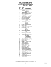
... F (82.2 C) 16 3977373 Bracket, Drum Light 17 3401338 Element, Heater 18 8066086 Drum Hole Plug 19 279457 Wire Kit, Terminal (For Heater Element Wiring Harness Repair) 20 489463 Screw, 8−18 x 5/8 21 3390647 Screw, 8−18 x 1/2 23 3976479 Pad, Sensor 24 3406124 Bulb 25 3402841 Lens, Drum Light 26 690997 Ring, Tri 27 3399506 Shaft, L.H. 28 3399507 Shaft, R.H. 29 3397590 Roller, Support 30 348197 Washer, Support 31 3359452 Nut, 3/8−...
... F (82.2 C) 16 3977373 Bracket, Drum Light 17 3401338 Element, Heater 18 8066086 Drum Hole Plug 19 279457 Wire Kit, Terminal (For Heater Element Wiring Harness Repair) 20 489463 Screw, 8−18 x 5/8 21 3390647 Screw, 8−18 x 1/2 23 3976479 Pad, Sensor 24 3406124 Bulb 25 3402841 Lens, Drum Light 26 690997 Ring, Tri 27 3399506 Shaft, L.H. 28 3399507 Shaft, R.H. 29 3397590 Roller, Support 30 348197 Washer, Support 31 3359452 Nut, 3/8−...


