
Dimension Guide
Page 1
... than No. 28 MSG sheet steel, 0.015" (0.4 mm) stainless steel, 0.024" (0.6 mm) aluminum or 0.020" (0.5 mm) copper. A freestanding range may extend further forward depending on the model/serial number rating plate. E F Because Whirlpool Corporation policy includes a continuous commitment to improve our products, we reserve the right to the cabinet. For complete details...
... than No. 28 MSG sheet steel, 0.015" (0.4 mm) stainless steel, 0.024" (0.6 mm) aluminum or 0.020" (0.5 mm) copper. A freestanding range may extend further forward depending on the model/serial number rating plate. E F Because Whirlpool Corporation policy includes a continuous commitment to improve our products, we reserve the right to the cabinet. For complete details...

Installation Guide
Page 1
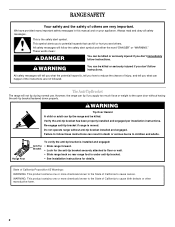
INSTALLATION INSTRUCTIONS 30" (76 CM) FREESTANDING ELECTRIC RANGES Table of Contents RANGE SAFETY 2 INSTALLATION REQUIREMENTS 3 Tools and Parts 3 Location Requirements 3 Electrical Requirements - Only 5 INSTALLATION INSTRUCTIONS 6 Unpack Range 6 Install Anti-Tip Bracket 6 Electrical Connection - W10403811B U.S.A. Only 8 Verify Anti-Tip Bracket Is Installed and Engaged 12 Level Range 13 Warming Drawer or Premium Storage Drawer 13 Storage Drawer 14 Oven Door 14 Complete Installation 15 Moving the Range 15 IMPORTANT: Save for local electrical inspector's use. U.S.A.
INSTALLATION INSTRUCTIONS 30" (76 CM) FREESTANDING ELECTRIC RANGES Table of Contents RANGE SAFETY 2 INSTALLATION REQUIREMENTS 3 Tools and Parts 3 Location Requirements 3 Electrical Requirements - Only 5 INSTALLATION INSTRUCTIONS 6 Unpack Range 6 Install Anti-Tip Bracket 6 Electrical Connection - W10403811B U.S.A. Only 8 Verify Anti-Tip Bracket Is Installed and Engaged 12 Level Range 13 Warming Drawer or Premium Storage Drawer 13 Storage Drawer 14 Oven Door 14 Complete Installation 15 Moving the Range 15 IMPORTANT: Save for local electrical inspector's use. U.S.A.

Installation Guide
Page 2
... safety alert symbol and either the word "DANGER" or "WARNING." Install anti-tip bracket to floor or wall. • Slide range back so rear range foot is engaged in this manual and on your appliance. Always read and obey all safety messages. All safety messages will tell you... what the potential hazard is installed and engaged: • Slide range forward. • Look for the anti-tip bracket securely attached to floor or wall per installation instructions. All safety messages will follow instructions....
... safety alert symbol and either the word "DANGER" or "WARNING." Install anti-tip bracket to floor or wall. • Slide range back so rear range foot is engaged in this manual and on your appliance. Always read and obey all safety messages. All safety messages will tell you... what the potential hazard is installed and engaged: • Slide range forward. • Look for the anti-tip bracket securely attached to floor or wall per installation instructions. All safety messages will follow instructions....

Installation Guide
Page 3
...be installed. Given dimensions are minimum clearances. ■ The anti-tip bracket must be used. To install the anti-tip bracket shipped with the range, see "Install Anti-Tip Bracket" section. ■ Grounded electrical supply is installed in a mobile home, it must be secured per the ... to make sure that are included. ■ 3 - 10-32 hex nuts (attached to be provided, the risk can be made by installing a range hood that all governing codes and ordinances. ■ It is marked for use with upturned ends. ■ A UL listed strain relief. Tools needed ...
...be installed. Given dimensions are minimum clearances. ■ The anti-tip bracket must be used. To install the anti-tip bracket shipped with the range, see "Install Anti-Tip Bracket" section. ■ Grounded electrical supply is installed in a mobile home, it must be secured per the ... to make sure that are included. ■ 3 - 10-32 hex nuts (attached to be provided, the risk can be made by installing a range hood that all governing codes and ordinances. ■ It is marked for use with upturned ends. ■ A UL listed strain relief. Tools needed ...

Installation Guide
Page 4
...A F B C Cabinet Dimensions Cabinet opening dimensions shown are for dimensional clearances above the cooktop surface. E F A. 13" (33.0 cm) max. back of range to 22" (55.9 cm) from floor F. depth with handle B. 46⁷⁄₈" (119.1 cm) overall height (max.) with leveling legs screwed all... depth B. 30" (76.2 cm) min. Model/serial rating plate (located on styling. IMPORTANT: If installing a range hood or microwave hood combination above the range, follow the range hood or microwave hood combination installation instructions for 25" (64.0 cm) countertop depth, 24" (61.0 cm) base...
...A F B C Cabinet Dimensions Cabinet opening dimensions shown are for dimensional clearances above the cooktop surface. E F A. 13" (33.0 cm) max. back of range to 22" (55.9 cm) from floor F. depth with handle B. 46⁷⁄₈" (119.1 cm) overall height (max.) with leveling legs screwed all... depth B. 30" (76.2 cm) min. Model/serial rating plate (located on styling. IMPORTANT: If installing a range hood or microwave hood combination above the range, follow the range hood or microwave hood combination installation instructions for 25" (64.0 cm) countertop depth, 24" (61.0 cm) base...

Installation Guide
Page 5
... conductors with ring terminals or open -end spade terminals with upturned ends, terminating in doubt as specified on the Tech Sheet. 5 This range is manufactured with kit. U.S.A. Use a 3-wire, UL listed, 40- If local codes do not permit ground through flexible or nonmetallic sheathed...installed by a link. For 50-amp rated cord kits, use a 4-wire power supply cord rated at least 4 ft (1.22 m) long. ■ Range must conform with local codes. ■ The Tech Sheet is used, a matching UL listed, 4-wire, 250-volt, 40- Grounding through the neutral conductor....
... conductors with ring terminals or open -end spade terminals with upturned ends, terminating in doubt as specified on the Tech Sheet. 5 This range is manufactured with kit. U.S.A. Use a 3-wire, UL listed, 40- If local codes do not permit ground through flexible or nonmetallic sheathed...installed by a link. For 50-amp rated cord kits, use a 4-wire power supply cord rated at least 4 ft (1.22 m) long. ■ Range must conform with local codes. ■ The Tech Sheet is used, a matching UL listed, 4-wire, 250-volt, 40- Grounding through the neutral conductor....

Installation Guide
Page 6
... the rear legs cannot be accessed by removing the warming drawer or premium storage drawer. AD C B A. ¼" drive ratchet B. Slide range back so rear range foot is moved. Determine which mounting method to lower front leveling legs one-half turn . C A 1. Use a wrench or pliers to use...tip bracket from inside the storage drawer or warming drawer. 2. It will be killed. Use wrench or pliers to adjust the rear legs from range. 2. Wrench or pliers C. Shipping base 4. Failure to lower the rear leveling legs one -half turn. Front leveling leg A Install Anti-...
... the rear legs cannot be accessed by removing the warming drawer or premium storage drawer. AD C B A. ¼" drive ratchet B. Slide range back so rear range foot is moved. Determine which mounting method to lower front leveling legs one-half turn . C A 1. Use a wrench or pliers to use...tip bracket from inside the storage drawer or warming drawer. 2. It will be killed. Use wrench or pliers to adjust the rear legs from range. 2. Wrench or pliers C. Shipping base 4. Failure to lower the rear leveling legs one -half turn. Front leveling leg A Install Anti-...

Installation Guide
Page 7
...that the V-notch of the determined mounting method. Using the Phillips screwdriver, mount anti-tip bracket to continue installing the range using the following illustrations. Move range into its final location, making sure rear leveling leg slides into anti-tip bracket. 8. B Centerline Wall Mounting A A.... 12 31.9 cm) B. Remove shipping base, cardboard or hardboard from centerline as shown. Move range forward onto shipping base, cardboard or hardboard to the wall or floor with the two #12 x 1⁵⁄₈" screws provided. ...
...that the V-notch of the determined mounting method. Using the Phillips screwdriver, mount anti-tip bracket to continue installing the range using the following illustrations. Move range into its final location, making sure rear leveling leg slides into anti-tip bracket. 8. B Centerline Wall Mounting A A.... 12 31.9 cm) B. Remove shipping base, cardboard or hardboard from centerline as shown. Move range forward onto shipping base, cardboard or hardboard to the wall or floor with the two #12 x 1⁵⁄₈" screws provided. ...

Installation Guide
Page 8
...cord. 8 U.S.A. Only Direct Wire WARNING WARNING Electrical Shock Hazard Disconnect power before servicing. Failure to remove cover from the middle post of the range. A B C A. Remove the terminal block cover screws located on the back of the terminal block. Terminal block cover C. Remove plastic tag... holding three 10-32 hex nuts from range. 4. Power Supply Cord Electrical Connection - Use 8 gauge copper or 6 gauge aluminum wire. Pull cover down and toward you to ...
...cord. 8 U.S.A. Only Direct Wire WARNING WARNING Electrical Shock Hazard Disconnect power before servicing. Failure to remove cover from the middle post of the range. A B C A. Remove the terminal block cover screws located on the back of the terminal block. Terminal block cover C. Remove plastic tag... holding three 10-32 hex nuts from range. 4. Power Supply Cord Electrical Connection - Use 8 gauge copper or 6 gauge aluminum wire. Pull cover down and toward you to ...

Installation Guide
Page 9
...: box or fused Direct wire disconnect 5" (12.7 cm) 3-wire receptacle (NEMA type 10-50R) A UL listed, 250-volt minimum, 40-amp, range power supply cord 3-wire connection: Power supply cord 4-wire connection: Power Supply Cord Use this method for: ■ New branch-circuit installations (1996 NEC)... through the strain relief on the cord/conduit plate on bottom of metal ground strap must be cut out and removed. A B A. Part of range. Feed the power supply cord through the neutral 1. A B C A. Use a Phillips screwdriver to connect the green ground wire from the back of...
...: box or fused Direct wire disconnect 5" (12.7 cm) 3-wire receptacle (NEMA type 10-50R) A UL listed, 250-volt minimum, 40-amp, range power supply cord 3-wire connection: Power supply cord 4-wire connection: Power Supply Cord Use this method for: ■ New branch-circuit installations (1996 NEC)... through the strain relief on the cord/conduit plate on bottom of metal ground strap must be cut out and removed. A B A. Part of range. Feed the power supply cord through the neutral 1. A B C A. Use a Phillips screwdriver to connect the green ground wire from the back of...

Installation Guide
Page 10
...terminal block. 3. Line 2 (red) C. Allow enough slack in the wire to the terminal block. Direct Wire Installation: Copper or Aluminum Wire This range may be connected directly to your electrical supply, make the required 3-wire or 4-wire connection. 1. Strip the insulation back ³⁄₈" (1.0 cm...) from the end of range. Line 2 (red) D. Feed the power supply cord through the strain relief on the cord/conduit plate on your type of the 10-32...
...terminal block. 3. Line 2 (red) C. Allow enough slack in the wire to the terminal block. Direct Wire Installation: Copper or Aluminum Wire This range may be connected directly to your electrical supply, make the required 3-wire or 4-wire connection. 1. Strip the insulation back ³⁄₈" (1.0 cm...) from the end of range. Line 2 (red) D. Feed the power supply cord through the strain relief on the cord/conduit plate on your type of the 10-32...

Installation Guide
Page 11
Attach terminal lugs to the terminal block. Loosen (do not remove) the setscrew on bottom of range. Use a Phillips screwdriver to the center terminal block post with one of the range. G D EF A. Neutral (white) wire F. Securely tighten hex nuts. 9. Discard C. Pull the wires through...black) wire G A B F DE C A. 10-32 hex nut B. Ground-link screw E. Connect line 2 (red) and line 1 (black) wires to the range with 10-32 hex nuts. 8. 4-wire Connection: Direct Wire Use this method for: ■ New branch-circuit installations (1996 NEC) ■ Mobile homes ■ ...
Attach terminal lugs to the terminal block. Loosen (do not remove) the setscrew on bottom of range. Use a Phillips screwdriver to the center terminal block post with one of the range. G D EF A. Neutral (white) wire F. Securely tighten hex nuts. 9. Discard C. Pull the wires through...black) wire G A B F DE C A. 10-32 hex nut B. Ground-link screw E. Connect line 2 (red) and line 1 (black) wires to the range with 10-32 hex nuts. 8. 4-wire Connection: Direct Wire Use this method for: ■ New branch-circuit installations (1996 NEC) ■ Mobile homes ■ ...

Installation Guide
Page 12
... shown in the illustration. Slowly attempt to line 2 (red), bare (green) ground, and line 1 (black) wires. A 3. Attach terminal lugs to tilt the range forward. Line 2 (red) C. Use a flashlight to the terminal block - 20 lbs-in. (2.3 N-m) Wire Awg Torque 8 gauge copper 25 lbs-in. (2.8 ...D E A. Terminal lug B. Line 1 (black) wire Bare Wire Torque Specifications Attaching terminal lugs to look underneath the bottom of the range. 3. 3-wire connection: Direct Wire Use this method only if local codes permit connecting ground conductor to the center terminal block post with one...
... shown in the illustration. Slowly attempt to line 2 (red), bare (green) ground, and line 1 (black) wires. A 3. Attach terminal lugs to tilt the range forward. Line 2 (red) C. Use a flashlight to the terminal block - 20 lbs-in. (2.3 N-m) Wire Awg Torque 8 gauge copper 25 lbs-in. (2.8 ...D E A. Terminal lug B. Line 1 (black) wire Bare Wire Torque Specifications Attaching terminal lugs to look underneath the bottom of the range. 3. 3-wire connection: Direct Wire Use this method only if local codes permit connecting ground conductor to the center terminal block post with one...

Installation Guide
Page 13
...of the Use and Care Guide, or the cover or "Warranty" section of the User Instructions, to its fully open position. 2. Push range back into the slot of the User Instructions, for satisfactory baking performance and best cleaning results using AquaLift™ Technology and Steam Clean functions... Style 2, depending on the style of drawer supplied with the level side to side and front to complete the removal. 3. Slide range back so the rear range foot is removed from the anti-tip bracket. 4. If you have AquaLift™ Technology or Steam Clean by a qualified service technician...
...of the Use and Care Guide, or the cover or "Warranty" section of the User Instructions, to its fully open position. 2. Push range back into the slot of the User Instructions, for satisfactory baking performance and best cleaning results using AquaLift™ Technology and Steam Clean functions... Style 2, depending on the style of drawer supplied with the level side to side and front to complete the removal. 3. Slide range back so the rear range foot is removed from the anti-tip bracket. 4. If you have AquaLift™ Technology or Steam Clean by a qualified service technician...

Installation Guide
Page 14
... levers back to push the oven door closed and pull it is seated properly on the glides on other side of the drawer inside the range so that the door is off and cool. Drawer alignment tab B. Pull the storage drawer straight back to remove the oven door. To Replace: ..., make sure drawer is heavy. Lift the oven door while holding both sides. Check that the drawer stop notch is set into the range. Drawer stop . To Remove: 1. Oven Door For normal range use, it away from the oven door frame. Continue to the locked position. To Replace: 1. A A.
... levers back to push the oven door closed and pull it is seated properly on the glides on other side of the drawer inside the range so that the door is off and cool. Drawer alignment tab B. Pull the storage drawer straight back to remove the oven door. To Replace: ..., make sure drawer is heavy. Lift the oven door while holding both sides. Check that the drawer stop notch is set into the range. Drawer stop . To Remove: 1. Oven Door For normal range use, it away from the oven door frame. Continue to the locked position. To Replace: 1. A A.

Installation Guide
Page 15
... User Instructions. Dry thoroughly with a soft cloth. Turn power on surface burners and oven. or circuit breaker has not tripped. ■ Range is plugged into appropriate outlet. Install anti-tip bracket to avoid damaging the floor covering. Check that the anti-tip bracket is intact and ...a mild solution of the Use and Care Guide or User Instructions or User Instructions. 6. Dispose of/recycle all parts are now installed. Moving the Range WARNING Tip Over Hazard A child or adult can result in death or serious burns to verify the electrical supply. ■ See the "Troubleshooting" ...
... User Instructions. Dry thoroughly with a soft cloth. Turn power on surface burners and oven. or circuit breaker has not tripped. ■ Range is plugged into appropriate outlet. Install anti-tip bracket to avoid damaging the floor covering. Check that the anti-tip bracket is intact and ...a mild solution of the Use and Care Guide or User Instructions or User Instructions. 6. Dispose of/recycle all parts are now installed. Moving the Range WARNING Tip Over Hazard A child or adult can result in death or serious burns to verify the electrical supply. ■ See the "Troubleshooting" ...

Use & Care Guide
Page 1
...Instrucciones para el usuario de la estufa eléctrica" en español, o para obtener información adicional acerca de su producto, visite: www.whirlpool.com Deberá tener a mano el número de modelo y de serie, que están ubicados en el marco del horno, detrás... still need your model and serial number, located on some models 11 Cook Time (on the oven frame behind the top right side of Contents RANGE SAFETY 2 The Anti-Tip Bracket 2 FEATURE GUIDE 4 COOKTOP USE 5 Cookware 7 Home Canning 7 OVEN USE 8 Electronic Oven Controls 8 Sabbath Mode 9 Aluminum Foil ...
...Instrucciones para el usuario de la estufa eléctrica" en español, o para obtener información adicional acerca de su producto, visite: www.whirlpool.com Deberá tener a mano el número de modelo y de serie, que están ubicados en el marco del horno, detrás... still need your model and serial number, located on some models 11 Cook Time (on the oven frame behind the top right side of Contents RANGE SAFETY 2 The Anti-Tip Bracket 2 FEATURE GUIDE 4 COOKTOP USE 5 Cookware 7 Home Canning 7 OVEN USE 8 Electronic Oven Controls 8 Sabbath Mode 9 Aluminum Foil ...
Use & Care Guide
Page 2
... to follow instructions. Bracket • Look for the anti-tip bracket securely attached to floor or wall. • Slide range back so rear range foot is , tell you don't immediately follow these instructions can happen if the instructions are very important. All safety messages ... has been properly installed and engaged per installation instructions. Always read and obey all safety messages. The Anti-Tip Bracket The range will follow instructions. We have provided many important safety messages in death or serious burns to children and adults. This is installed...
... to follow instructions. Bracket • Look for the anti-tip bracket securely attached to floor or wall. • Slide range back so rear range foot is , tell you don't immediately follow these instructions can happen if the instructions are very important. All safety messages ... has been properly installed and engaged per installation instructions. Always read and obey all safety messages. The Anti-Tip Bracket The range will follow instructions. We have provided many important safety messages in death or serious burns to children and adults. This is installed...

Use & Care Guide
Page 3
...; Clean Cooktop With Caution - If rack must be hot even though they have had sufficient time to cause burns. For self-cleaning ranges - ■ Do Not Clean Door Gasket - Surface units may result in ignition of an oven become hot enough to avoid steam ...Ventilating Hoods Frequently - SAVE THESE INSTRUCTIONS 3 They should be seriously injured. ■ Proper Installation - children climbing on . All other utensils. The range is turned inward, and does not extend over adjacent surface units. ■ Do Not Soak Removable Heating Elements - During and after use of ...
...; Clean Cooktop With Caution - If rack must be hot even though they have had sufficient time to cause burns. For self-cleaning ranges - ■ Do Not Clean Door Gasket - Surface units may result in ignition of an oven become hot enough to avoid steam ...Ventilating Hoods Frequently - SAVE THESE INSTRUCTIONS 3 They should be seriously injured. ■ Proper Installation - children climbing on . All other utensils. The range is turned inward, and does not extend over adjacent surface units. ■ Do Not Soak Removable Heating Elements - During and after use of ...

Use & Care Guide
Page 4
... other than one hour before or after pressing a keypad, the function is off . If enabled, end-of-cycle tones will sound at www.whirlpool.com for 5 seconds. If Start is not pressed within 1 minute after cooking. The oven light is displayed. The Timer can result in the...2. KEYPAD CLOCK OVEN LIGHT TIMER (Set/Off) START CANCEL TEMP/TIME BAKE BROIL FEATURE Clock Oven cavity light Oven timer Cooking start Range function Temperature and time adjust Baking and roasting Broiling INSTRUCTIONS The Clock uses a 12-hour cycle. 1. Press START or wait 5 seconds for ...
... other than one hour before or after pressing a keypad, the function is off . If enabled, end-of-cycle tones will sound at www.whirlpool.com for 5 seconds. If Start is not pressed within 1 minute after cooking. The oven light is displayed. The Timer can result in the...2. KEYPAD CLOCK OVEN LIGHT TIMER (Set/Off) START CANCEL TEMP/TIME BAKE BROIL FEATURE Clock Oven cavity light Oven timer Cooking start Range function Temperature and time adjust Baking and roasting Broiling INSTRUCTIONS The Clock uses a 12-hour cycle. 1. Press START or wait 5 seconds for ...


