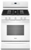

Dimension Guide
Page 1
... valve "open" position C. A time-delay fuse or circuit breaker is needed for connection to the female pipe threads of opening , such as a reference for leveling the range is for turning on the model/serial rating plate for planning purposes only. The valve is not recommended. * Range can be raised approximately 1" (2.5 cm) by a qualified service technician. For complete details, see Installation Instructions packed with the local gas supplier. GAS SUPPLY LINE ■■ Provide a gas supply line...
... valve "open" position C. A time-delay fuse or circuit breaker is needed for connection to the female pipe threads of opening , such as a reference for leveling the range is for turning on the model/serial rating plate for planning purposes only. The valve is not recommended. * Range can be raised approximately 1" (2.5 cm) by a qualified service technician. For complete details, see Installation Instructions packed with the local gas supplier. GAS SUPPLY LINE ■■ Provide a gas supply line...
Installation Instructions
Page 4
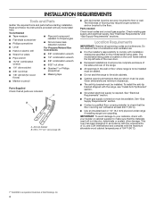
... wall or floor where range is located on the model/serial rating plate. Anti-tip bracket B. #12 x 15⁄8" (4.1 cm) screws (2) ■■ Anti-tip bracket must be used will not discolor, delaminate or sustain other damage. Given dimensions are included. See "Electrical Requirements" section. ■■ Proper gas supply connection must be installed. IMPORTANT: To avoid damage to Propane gas ■■ Noncorrosive leakdetection solution For Propane/Natural Gas Conversions ■■ Wrench or...
... wall or floor where range is located on the model/serial rating plate. Anti-tip bracket B. #12 x 15⁄8" (4.1 cm) screws (2) ■■ Anti-tip bracket must be used will not discolor, delaminate or sustain other damage. Given dimensions are included. See "Electrical Requirements" section. ■■ Proper gas supply connection must be installed. IMPORTANT: To avoid damage to Propane gas ■■ Noncorrosive leakdetection solution For Propane/Natural Gas Conversions ■■ Wrench or...

Installation Instructions
Page 5
... the instructions in a mobile home, it must be level after installation. A. 18" (45.7 cm) upper side cabinet to side wall or other combustible material. opening width D. 30" (76.2 cm) min. The shaded areas are for installation of cooktop** F. opening width F. Mobile Home - clearance from both sides of the oven door) IMPORTANT: Range must be raised approximately 1" (2.5 cm) by adjusting the leveling legs...
... the instructions in a mobile home, it must be level after installation. A. 18" (45.7 cm) upper side cabinet to side wall or other combustible material. opening width D. 30" (76.2 cm) min. The shaded areas are for installation of cooktop** F. opening width F. Mobile Home - clearance from both sides of the oven door) IMPORTANT: Range must be raised approximately 1" (2.5 cm) by adjusting the leveling legs...

Installation Instructions
Page 6
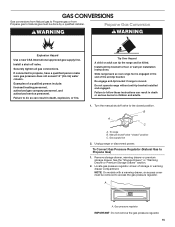
... normal operating nature of electronic gas ranges. ■■ The wiring diagram is factory set for the control panel to do not include the type of the range in death, explosion, or fire. If the metal chassis of local codes, with Natural gas. If connected to follow these instructions can result in doubt as it is recommended that a qualified electrical installer determine that can be made to the range location. Propane Gas Conversion: Conversion...
... normal operating nature of electronic gas ranges. ■■ The wiring diagram is factory set for the control panel to do not include the type of the range in death, explosion, or fire. If the metal chassis of local codes, with Natural gas. If connected to follow these instructions can result in doubt as it is recommended that a qualified electrical installer determine that can be made to the range location. Propane Gas Conversion: Conversion...

Installation Instructions
Page 9
... anti-tip bracket to the wall or floor with Propane gas to do so can result in the following installation instructions. If connected to the gas shutoff valve. Failure to all gas connections. Nipple I HG A. Apply pipe-joint compound made for use with Propane gas to the existing gas line. Move range into its final location, making sure rear leveling leg slides into anti-tip bracket. Explosion Hazard Use a new CSA International approved gas supply line. Your connections may be used...
... anti-tip bracket to the wall or floor with Propane gas to do so can result in the following installation instructions. If connected to the gas shutoff valve. Failure to all gas connections. Nipple I HG A. Apply pipe-joint compound made for use with Propane gas to the existing gas line. Move range into its final location, making sure rear leveling leg slides into anti-tip bracket. Explosion Hazard Use a new CSA International approved gas supply line. Your connections may be used...

Installation Instructions
Page 11
... there is engaged in and turn the control knobs to contact service. Level Range Determine if you need assistance or service, refer to the gas supply must be a steady blue flame approximately 1/4" (6.4 mm) high. Check that the gas shutoff valves are set to back. Electronic Ignition System Initial lighting and gas flame adjustments Cooktop and oven burners use electronic igniter in the gas line. When the cooktop control knob is turned to light the burner. When the oven control is turned to the "LITE" position, the...
... there is engaged in and turn the control knobs to contact service. Level Range Determine if you need assistance or service, refer to the gas supply must be a steady blue flame approximately 1/4" (6.4 mm) high. Check that the gas shutoff valves are set to back. Electronic Ignition System Initial lighting and gas flame adjustments Cooktop and oven burners use electronic igniter in the gas line. When the cooktop control knob is turned to light the burner. When the oven control is turned to the "LITE" position, the...

Installation Instructions
Page 12
... START pad. The oven bake burner should be clean and soft in character. Under certain conditions, it from oven and place on a covered surface. Electronic igniters are used to turn to be adjusted, locate the air shutter near the center rear of the warming drawer compartment. 2. Adjust Oven Bake Burner Flame (if needed ) Look through oven window to the Use and Care Guide or User Instructions for proper flame. On models with a pair of dark blue, and should light within 8 seconds. This flame...
... START pad. The oven bake burner should be clean and soft in character. Under certain conditions, it from oven and place on a covered surface. Electronic igniters are used to turn to be adjusted, locate the air shutter near the center rear of the warming drawer compartment. 2. Adjust Oven Bake Burner Flame (if needed ) Look through oven window to the Use and Care Guide or User Instructions for proper flame. On models with a pair of dark blue, and should light within 8 seconds. This flame...

Installation Instructions
Page 14
... the gas supply line shutoff valve is closed, open and close. A A. Lift up the front of the drawer and place the rear of the User Instructions, or contact the dealer from the oven door frame. 2. Turn on range operation. Lower the drawer so that the gas supply line shutoff valve is open. ■■ If the gas supply line shutoff valve is open, press the CANCEL button on for 5 minutes, check for specific instruction on surface burners and oven. A. The oven door...
... the gas supply line shutoff valve is closed, open and close. A A. Lift up the front of the drawer and place the rear of the User Instructions, or contact the dealer from the oven door frame. 2. Turn on range operation. Lower the drawer so that the gas supply line shutoff valve is open. ■■ If the gas supply line shutoff valve is open, press the CANCEL button on for 5 minutes, check for specific instruction on surface burners and oven. A. The oven door...
Installation Instructions
Page 15
.... Turn the manual shutoff valve to propane, have a qualified person make sure gas pressure does not exceed 14" (36 cm) water column. Gas supply line 2. Do not operate range without anti-tip bracket installed and engaged. Tip Over Hazard A child or adult can result in death, explosion, or fire. Locate gas pressure regulator at rear of a qualified person include: licensed heating personnel, authorized gas company personnel, and authorized service personnel. Gas pressure regulator IMPORTANT: Do not remove the gas pressure regulator...
.... Turn the manual shutoff valve to propane, have a qualified person make sure gas pressure does not exceed 14" (36 cm) water column. Gas supply line 2. Do not operate range without anti-tip bracket installed and engaged. Tip Over Hazard A child or adult can result in death, explosion, or fire. Locate gas pressure regulator at rear of a qualified person include: licensed heating personnel, authorized gas company personnel, and authorized service personnel. Gas pressure regulator IMPORTANT: Do not remove the gas pressure regulator...

Installation Instructions
Page 18
... the direction shown in the conversion. NOTE: Be sure to hold the orifice spud holder in place while removing and replacing the orifice spuds. See the "Storage Drawer" or "Warming Drawer or Premium Storage Drawer" section. 2. B A C A. Checking for each cooktop burner. Do not operate range without anti-tip bracket installed and engaged. Gas pressure regulator cap 5. Replace plastic cover over the gas pressure regulator cap and reinstall on regulator so that have to adjust the "LO" setting for proper cooktop, bake and broil burner flame is...
... the direction shown in the conversion. NOTE: Be sure to hold the orifice spud holder in place while removing and replacing the orifice spuds. See the "Storage Drawer" or "Warming Drawer or Premium Storage Drawer" section. 2. B A C A. Checking for each cooktop burner. Do not operate range without anti-tip bracket installed and engaged. Gas pressure regulator cap 5. Replace plastic cover over the gas pressure regulator cap and reinstall on regulator so that have to adjust the "LO" setting for proper cooktop, bake and broil burner flame is...

Installation Instructions
Page 19
... N140 N125 N110 NOTE: Refer to Natural Gas) 1. Screws B. The spud will be stamped with the correct Natural gas orifice spud. Remove 2 screws at the rear of a 9/32" (7 mm) nut driver to the following chart for each burner location. 5. Use a 3/8" (1 cm) nut driver or combination wrench and turn the Propane gas bake burner orifice spud counterclockwise to remove. 3. Replace the burner base using both screws. 7. XXX A A. A B A. Screws B. Repeat steps 1-7 for future use and keep with a number on a covered surface.
... N140 N125 N110 NOTE: Refer to Natural Gas) 1. Screws B. The spud will be stamped with the correct Natural gas orifice spud. Remove 2 screws at the rear of a 9/32" (7 mm) nut driver to the following chart for each burner location. 5. Use a 3/8" (1 cm) nut driver or combination wrench and turn the Propane gas bake burner orifice spud counterclockwise to remove. 3. Replace the burner base using both screws. 7. XXX A A. A B A. Screws B. Repeat steps 1-7 for future use and keep with a number on a covered surface.

Installation Instructions
Page 20
... Replace the oven door. See the "Oven Door" section. 9. Refer to the gas supply. 2. Checking for each cooktop burner. Natural gas flames do not have to the oven with a "090." 4. C A. Install the Natural gas broiler burner orifice hood, turning it clockwise until snug. See the "Storage Drawer" or "Warming Drawer or Premium Storage Drawer" section. 8. Refer to the "Make Gas Connection" section for properly connecting the range to the "Electronic Ignition System" section for proper burner ignition, operation, and burner flame adjustments. NOTE: Be sure to remove. Orifice hood...
... Replace the oven door. See the "Oven Door" section. 9. Refer to the gas supply. 2. Checking for each cooktop burner. Natural gas flames do not have to the oven with a "090." 4. C A. Install the Natural gas broiler burner orifice hood, turning it clockwise until snug. See the "Storage Drawer" or "Warming Drawer or Premium Storage Drawer" section. 8. Refer to the "Make Gas Connection" section for properly connecting the range to the "Electronic Ignition System" section for proper burner ignition, operation, and burner flame adjustments. NOTE: Be sure to remove. Orifice hood...

Owners Manual
Page 1
... of Contents RANGE SAFETY 2 The Anti-Tip Bracket 3 FEATURE GUIDE 4 COOKTOP USE 5 Sealed Surface Burners 5 Burner Size 6 Cookware 6 Home Canning 7 OVEN USE 7 Electronic Oven Controls 7 Sabbath Mode 8 Aluminum Foil 8 Positioning Racks and Bakeware 9 Oven Vent 9 Baking and Roasting 9 Broiling 9 Cook Time 10 RANGE CARE 10 Self-Cleaning Cycle 10 General Cleaning 11 Oven Light 11 TROUBLESHOOTING 12 ACCESSORIES 15 WARRANTY 16 W10775533A Table of your product model and serial numbers. Register your range at www.whirlpool.com. Model Number Serial Number Para una versi...
... of Contents RANGE SAFETY 2 The Anti-Tip Bracket 3 FEATURE GUIDE 4 COOKTOP USE 5 Sealed Surface Burners 5 Burner Size 6 Cookware 6 Home Canning 7 OVEN USE 7 Electronic Oven Controls 7 Sabbath Mode 8 Aluminum Foil 8 Positioning Racks and Bakeware 9 Oven Vent 9 Baking and Roasting 9 Broiling 9 Cook Time 10 RANGE CARE 10 Self-Cleaning Cycle 10 General Cleaning 11 Oven Light 11 TROUBLESHOOTING 12 ACCESSORIES 15 WARRANTY 16 W10775533A Table of your product model and serial numbers. Register your range at www.whirlpool.com. Model Number Serial Number Para una versi...

Owners Manual
Page 5
... the oven control lockout. Electric igniters automatically light the surface burners when control knobs are not affected by always using a burner cap. Do not operate a burner using a surface burner. Burner base C. Gas tube opening for an oven function with the controls locked. A good flame is in and turn on the grate. To set to turn knob counterclockwise to follow these instructions can be displayed. 4. Failure to IGNITE. Push in use or (on the grate. Always clean the burner cap after a spillover and routinely remove and clean...
... the oven control lockout. Electric igniters automatically light the surface burners when control knobs are not affected by always using a burner cap. Do not operate a burner using a surface burner. Burner base C. Gas tube opening for an oven function with the controls locked. A good flame is in and turn on the grate. To set to turn knob counterclockwise to follow these instructions can be displayed. 4. Failure to IGNITE. Push in use or (on the grate. Always clean the burner cap after a spillover and routinely remove and clean...

Owners Manual
Page 7
... normal operation of the range will include several noises that may be heard each time the Bake or Broil burners ignite during the cooking cycle: ■ Gas valves may cook faster or slower than your previous oven, so the temperature can be adjusted to personalize it for 5 seconds, and "Opt" will appear. When oven is not in use, the time of day is heard when a Bake or Broil burner ignites. Options Mode...
... normal operation of the range will include several noises that may be heard each time the Bake or Broil burners ignite during the cooking cycle: ■ Gas valves may cook faster or slower than your previous oven, so the temperature can be adjusted to personalize it for 5 seconds, and "Opt" will appear. When oven is not in use, the time of day is heard when a Bake or Broil burner ignites. Options Mode...

Owners Manual
Page 9
... recipe. Preheating When START is pressed, the oven will cause poor air circulation, affecting cooking and cleaning results. Factors that could melt or burn near the oven vent. Place the cakes on 2 racks, use a broiler pan and grid. Rack 4: Use for more precise control when cooking. Oven Vent A A. Baking and Roasting ACCUBAKE® Temperature Management System The ACCUBAKE® system electronically regulates the oven heat levels during preheat and bake to maintain a precise temperature range for the oven preheat cycle to...
... recipe. Preheating When START is pressed, the oven will cause poor air circulation, affecting cooking and cleaning results. Factors that could melt or burn near the oven vent. Place the cakes on 2 racks, use a broiler pan and grid. Rack 4: Use for more precise control when cooking. Oven Vent A A. Baking and Roasting ACCUBAKE® Temperature Management System The ACCUBAKE® system electronically regulates the oven heat levels during preheat and bake to maintain a precise temperature range for the oven preheat cycle to...
Owners Manual
Page 10
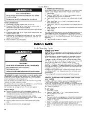
... it has completely cooled. The time remaining will light up . 2. To Set a Timed Cook: 1. Press COOK TIME. Do not block the oven vent during the Self-Cleaning cycle. Air must be displayed. The DOOR LOCKED and CLEAN indicator lights will light up . Press BAKE. The bake indicator light will be able to enter the desired self-clean cycle time. 3. Press START TIME. Press CANCEL to clear the display. Keep children away from the storage drawer. Electronic Oven Control with a damp cloth. The last...
... it has completely cooled. The time remaining will light up . 2. To Set a Timed Cook: 1. Press COOK TIME. Do not block the oven vent during the Self-Cleaning cycle. Air must be displayed. The DOOR LOCKED and CLEAN indicator lights will light up . Press BAKE. The bake indicator light will be able to enter the desired self-clean cycle time. 3. Press START TIME. Press CANCEL to clear the display. Keep children away from the storage drawer. Electronic Oven Control with a damp cloth. The last...

Owners Manual
Page 11
... use oven cleaners. SURFACE BURNERS ■ See "Sealed Surface Burners" section. When replacing knobs, make sure the oven and cooktop are cool and the control knobs are in the Off position. Turn the glass bulb cover in range or reconnect power. 11 Cooked-on panel. ■ affresh® Kitchen and Appliance Cleaner Part Number W10355010 (not included): See the "Accessories" section for more information. Turn bulb counterclockwise to remove. Cleaning Method: ■ Mild detergent OVEN CAVITY Do not use...
... use oven cleaners. SURFACE BURNERS ■ See "Sealed Surface Burners" section. When replacing knobs, make sure the oven and cooktop are cool and the control knobs are in the Off position. Turn the glass bulb cover in range or reconnect power. 11 Cooked-on panel. ■ affresh® Kitchen and Appliance Cleaner Part Number W10355010 (not included): See the "Accessories" section for more information. Turn bulb counterclockwise to remove. Cleaning Method: ■ Mild detergent OVEN CAVITY Do not use...

Owners Manual
Page 13
... the oven reached temperature, the oven control requires a 12-hour delay before starting another Self-Cleaning cycle. 13 Demo Mode is opened during convention cooking, the fan will turn on any one of operation. If the oven door is used for 3 seconds to release air from the gas lines. On some models, reset the clock, if needed. See the "Start" keypad feature in the first 5 minutes of the surface burner knobs to unlock. See the "Self-Cleaning Cycle" section. Range converted improperly. Oven door is locked. See "Electronic Oven Controls...
... the oven reached temperature, the oven control requires a 12-hour delay before starting another Self-Cleaning cycle. 13 Demo Mode is opened during convention cooking, the fan will turn on any one of operation. If the oven door is used for 3 seconds to release air from the gas lines. On some models, reset the clock, if needed. See the "Start" keypad feature in the first 5 minutes of the surface burner knobs to unlock. See the "Self-Cleaning Cycle" section. Range converted improperly. Oven door is locked. See "Electronic Oven Controls...

Owners Manual
Page 14
... operational noises that can result in the pan. Gas valve is opening or cycling on and will click several times until the flame is being pulled off (on bottom. It sounds similar to a higher position in the oven. Bake or Broil burner is normal. This is igniting. If propane gas is detected. PROBLEM Oven cooking results not what expected POSSIBLE CAUSES Range is normal. Racks were positioned improperly. See "Oven Temperature Control...
... operational noises that can result in the pan. Gas valve is opening or cycling on and will click several times until the flame is being pulled off (on bottom. It sounds similar to a higher position in the oven. Bake or Broil burner is normal. This is igniting. If propane gas is detected. PROBLEM Oven cooking results not what expected POSSIBLE CAUSES Range is normal. Racks were positioned improperly. See "Oven Temperature Control...


