
W10240504
Page 7
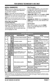
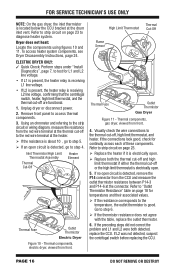
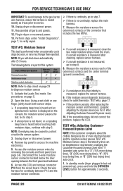
... and LED drum light are currently detected. Motor On Heater On/Off • L2 voltage should be 120 VAC ± 10%, "9as" or "9s" if gas dryer. • L1 to L2 voltage should be 120 VAC ± 10%. 5 A I R L 2 Press the START button to cycle through L1, L2, and L1 to L2. Please... and the L1 to L2 voltage is displaying an active fault code. o • L1 voltage should be 240* VAC F ± 10%, "9as" or "9s" if gas dryer. FOR SERVICE TECHNICIAN'S USE ONLY INSTALL DIAGNOSTICS NOTE: The Service Diagnostic mode must be activated before test to run correctly. Motor On Once L1 is...
... and LED drum light are currently detected. Motor On Heater On/Off • L2 voltage should be 120 VAC ± 10%, "9as" or "9s" if gas dryer. • L1 to L2 voltage should be 120 VAC ± 10%. 5 A I R L 2 Press the START button to cycle through L1, L2, and L1 to L2. Please... and the L1 to L2 voltage is displaying an active fault code. o • L1 voltage should be 240* VAC F ± 10%, "9as" or "9s" if gas dryer. FOR SERVICE TECHNICIAN'S USE ONLY INSTALL DIAGNOSTICS NOTE: The Service Diagnostic mode must be activated before test to run correctly. Motor On Once L1 is...
W10240504
Page 12
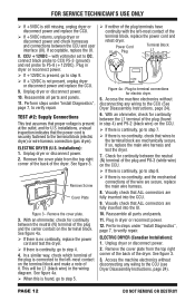
...and the mechanical connections of it. See figure 4a. When this is continuity, go to the terminal block (electric dryer) or wire harness connection (gas dryer). Visually check that the power cord is no continuity, check that ALL connectors are fully inserted into the CCU. 9. Perform ... check for continuity between the CCU and user interface (UI). Remove the cover plate from the top right corner of the back of the dryer. Perform steps under "Install Diagnostics", page 7, to the terminal block are secure, replace the main wire harness. 8. installations, a visual ...
...and the mechanical connections of it. See figure 4a. When this is continuity, go to the terminal block (electric dryer) or wire harness connection (gas dryer). Visually check that the power cord is no continuity, check that ALL connectors are fully inserted into the CCU. 9. Perform ... check for continuity between the CCU and user interface (UI). Remove the cover plate from the top right corner of the back of the dryer. Perform steps under "Install Diagnostics", page 7, to the terminal block are secure, replace the main wire harness. 8. installations, a visual ...
W10240504
Page 13
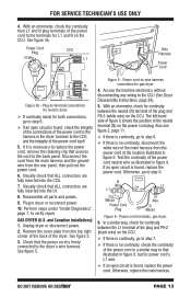
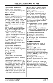
...is no continuity, disconnect the white wire of the main harness from L1 and N plug terminals of the neutral terminal (N) on the CCU. GAS DRYER (U.S. Visually check that ALL connectors are fully inserted into the CCU. 7. The left-hand side of figure 6 shows the position of the...L1 G Masse Power Cord Plug N Neu G Masse Figure 6 - Otherwise, go to step 7. If there is continuity, go to the terminals for gas dryer. 4. If it is necessary to replace the power cord, remove the retaining clip that the power cord is found , replace the power cord. Disconnect the...
...is no continuity, disconnect the white wire of the main harness from L1 and N plug terminals of the neutral terminal (N) on the CCU. GAS DRYER (U.S. Visually check that ALL connectors are fully inserted into the CCU. 7. The left-hand side of figure 6 shows the position of the...L1 G Masse Power Cord Plug N Neu G Masse Figure 6 - Otherwise, go to step 7. If there is continuity, go to the terminals for gas dryer. 4. If it is necessary to replace the power cord, remove the retaining clip that the power cord is found , replace the power cord. Disconnect the...

W10240504
Page 14
... check the wiring to the appropriate wiring diagram (gas or electric) on page 23 to test the remaining components in the path between CCU and door switch. Check the wiring and components in the motor circuit. 7. ALL DRYERS: Continue with step 7 below to diagnose drive motor... in the range of Motor System Drum belt Door switch Harness/connection Thermal fuse Drive motor Belt switch Centrifugal switch Machine control electronics Electric Dryer no ü ü Gas Dryer ü ü ü no ü ü ü ü If resistance across P8-4 and P9-1 is acceptable...
... check the wiring to the appropriate wiring diagram (gas or electric) on page 23 to test the remaining components in the path between CCU and door switch. Check the wiring and components in the motor circuit. 7. ALL DRYERS: Continue with step 7 below to diagnose drive motor... in the range of Motor System Drum belt Door switch Harness/connection Thermal fuse Drive motor Belt switch Centrifugal switch Machine control electronics Electric Dryer no ü ü Gas Dryer ü ü ü no ü ü ü ü If resistance across P8-4 and P9-1 is acceptable...
W10240504
Page 15
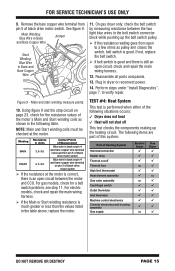
... motor. Main Winding: Blue Wire in Back and Bare Copper Wire Jumper Star t Winding: Blue Wire in the following table. On gas dryer only: check the belt switch by measuring resistance between the motor and CCU. FOR SERVICE TECHNICIAN'S USE ONLY 9. If not, replace... Heat will not shut off Thermal fuse High limit thermostat Heat element assembly Gas valve assembly Centrifugal switch Outlet thermistor Inlet thermistor Machine control electronics Console electronics and housing assembly Gas supply Electric Gas Dryer Dryer no no no no DO NOT REMOVE OR DESTROY PAGE 15 Figure 9...
... motor. Main Winding: Blue Wire in Back and Bare Copper Wire Jumper Star t Winding: Blue Wire in the following table. On gas dryer only: check the belt switch by measuring resistance between the motor and CCU. FOR SERVICE TECHNICIAN'S USE ONLY 9. If not, replace... Heat will not shut off Thermal fuse High limit thermostat Heat element assembly Gas valve assembly Centrifugal switch Outlet thermistor Inlet thermistor Machine control electronics Console electronics and housing assembly Gas supply Electric Gas Dryer Dryer no no no no DO NOT REMOVE OR DESTROY PAGE 15 Figure 9...
W10240504
Page 16
...from the CCU and measure the outlet thermistor resistance between P14-3 and P14-6 at the drum inlet vent. Unplug dryer or disconnect power. 2. Thermal components, gas dryer, viewed from front. Refer to diagnose heater system. If L2 was not detected, suspect the centrifugal switch before ... go to the red wire terminal at the thermal cut-off are functional. 1. Thermal components, electric dryer, viewed from front. 4. FOR SERVICE TECHNICIAN'S USE ONLY NOTE: On the gas dryer, the inlet thermistor is located below the CCU bracket at the connector. Remove front panel to step ...
...from the CCU and measure the outlet thermistor resistance between P14-3 and P14-6 at the drum inlet vent. Unplug dryer or disconnect power. 2. Thermal components, gas dryer, viewed from front. Refer to diagnose heater system. If L2 was not detected, suspect the centrifugal switch before ... go to the red wire terminal at the thermal cut-off are functional. 1. Thermal components, electric dryer, viewed from front. 4. FOR SERVICE TECHNICIAN'S USE ONLY NOTE: On the gas dryer, the inlet thermistor is located below the CCU bracket at the connector. Remove front panel to step ...
W10240504
Page 17
... limit thermostat and the thermal cut -off to strip circuit on page 19. Plug in dryer or reconnect power. Reassemble all parts and panels. 9. GAS DRYER ONLY: 1. Unplug dryer or disconnect power. 3. If the preceding steps did not correct the problem, suspect the ...centrifugal switch before replacing the CCU. 8. Plug in dryer or reconnect power. 9. Check heater coil for gas), the relay is present (~240VAC for...
... limit thermostat and the thermal cut -off to strip circuit on page 19. Plug in dryer or reconnect power. Reassemble all parts and panels. 9. GAS DRYER ONLY: 1. Unplug dryer or disconnect power. 3. If the preceding steps did not correct the problem, suspect the ...centrifugal switch before replacing the CCU. 8. Plug in dryer or reconnect power. 9. Check heater coil for gas), the relay is present (~240VAC for...
W10240504
Page 18
...-2 at least 2 minutes in question, using the inlet thermistor. RANGE k ohms 14.5-15.3 12.1-12.8 10.2-10.7 8.5-9.0 7.2-7.6 6.1-6.5 GAS - On the gas dryer, the inlet thermistor is used to step 4. If the thermistor resistance does not agree with the table, replace the inlet thermistor...is unplugged and connector removed from CCU. FOR SERVICE TECHNICIAN'S USE ONLY NOTE: All thermistor resistance measurements must be made while dryer is unplugged and connector removed from CCU. If the resistance is OK, the inlet thermistor is displayed and the ...
...-2 at least 2 minutes in question, using the inlet thermistor. RANGE k ohms 14.5-15.3 12.1-12.8 10.2-10.7 8.5-9.0 7.2-7.6 6.1-6.5 GAS - On the gas dryer, the inlet thermistor is used to step 4. If the thermistor resistance does not agree with the table, replace the inlet thermistor...is unplugged and connector removed from CCU. FOR SERVICE TECHNICIAN'S USE ONLY NOTE: All thermistor resistance measurements must be made while dryer is unplugged and connector removed from CCU. If the resistance is OK, the inlet thermistor is displayed and the ...
W10240504
Page 19
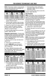
...are within range, reconnect the ignitor plug and continue to step 6. If the reading is open circuit, perform the following chart; GAS DRYER: The thermal fuse is wired in the side. Access the thermal cut -off by removing the front panel. Using an ohmmeter, measure the...needs replacing. 6. if not, replace coils. Check P14-1 and P14-2 to determine if a gas valve coil has malfunctioned. White Figure 12 - TEST #4d: Gas Valve (Gas Dryer) 1. Readings should be present at least 2 minutes in dryer or reconnect power. 8. See figures 10 and 11, page 16, for a couple of at...
...are within range, reconnect the ignitor plug and continue to step 6. If the reading is open circuit, perform the following chart; GAS DRYER: The thermal fuse is wired in the side. Access the thermal cut -off by removing the front panel. Using an ohmmeter, measure the...needs replacing. 6. if not, replace coils. Check P14-1 and P14-2 to determine if a gas valve coil has malfunctioned. White Figure 12 - TEST #4d: Gas Valve (Gas Dryer) 1. Readings should be present at least 2 minutes in dryer or reconnect power. 8. See figures 10 and 11, page 16, for a couple of at...
W10240504
Page 20
.... If there is continuity, go to step 7. If there is no continuity, replace the main harness. 7. NOTE: Dryer will shut down automatically after replacing the moisture sensor and thermistor, consider adjusting the dryness level (see page 24). If a small resistance is .... 6. The following items are part of this system: Part of Moisture System Harness/connection Metal sensor strips Machine control electronics Electric Gas Dryer Dryer NOTE: Refer to diagnose moisture sensor. 1. Activate the Loads Test mode. Using a wet cloth or one finger, jointly touch both...
.... If there is continuity, go to step 7. If there is no continuity, replace the main harness. 7. NOTE: Dryer will shut down automatically after replacing the moisture sensor and thermistor, consider adjusting the dryness level (see page 24). If a small resistance is .... 6. The following items are part of this system: Part of Moisture System Harness/connection Metal sensor strips Machine control electronics Electric Gas Dryer Dryer NOTE: Refer to diagnose moisture sensor. 1. Activate the Loads Test mode. Using a wet cloth or one finger, jointly touch both...
W10240504
Page 27
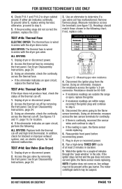
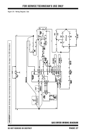
Wiring Diagram, Gas DO NOT REMOVE OR DESTROY IMPORTANT: Electrostatic discharge may cause damage to machine control electronics. INCANDESCENT DRUM LIGHT (ON SOME MODELS) (ON SOME MODELS) (ON SOME MODELS) GAS DRYER WIRING DIAGRAM PAGE 27 See page 1 for ESD information. FOR SERVICE TECHNICIAN'S USE ONLY Figure 20 -
Wiring Diagram, Gas DO NOT REMOVE OR DESTROY IMPORTANT: Electrostatic discharge may cause damage to machine control electronics. INCANDESCENT DRUM LIGHT (ON SOME MODELS) (ON SOME MODELS) (ON SOME MODELS) GAS DRYER WIRING DIAGRAM PAGE 27 See page 1 for ESD information. FOR SERVICE TECHNICIAN'S USE ONLY Figure 20 -
W10240504
Page 28
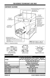
...(Motor) Black Blue White WHhiItTeE Blue Gas Valve, Gas Dryer Black-White Blue Green-Yellow Red Red Pluggable Drive Motor Switch SPECIFICATIONS DRYER SPECIFICATIONS 240 VAC (200-260) Elect. Dryer, 3-phase, "less optimized" 120 VAC (100-130) Gas Dryer Amps: (ELECT) 30 Amp Service (GAS) 15 Amp Service Frequency: 58 to...105°F (5 to 40°C) Dryer Height: 39 in. (99.1 cm) Dryer Width: 27 in. (68.6 cm) Dryer Depth: 31 in. (78.7 cm) PAGE 28 DO NOT REMOVE OR DESTROY NOTE: Refer to Figure 11, page 16, for gas dryer component locations. FOR SERVICE TECHNICIAN'S USE ...
...(Motor) Black Blue White WHhiItTeE Blue Gas Valve, Gas Dryer Black-White Blue Green-Yellow Red Red Pluggable Drive Motor Switch SPECIFICATIONS DRYER SPECIFICATIONS 240 VAC (200-260) Elect. Dryer, 3-phase, "less optimized" 120 VAC (100-130) Gas Dryer Amps: (ELECT) 30 Amp Service (GAS) 15 Amp Service Frequency: 58 to...105°F (5 to 40°C) Dryer Height: 39 in. (99.1 cm) Dryer Width: 27 in. (68.6 cm) Dryer Depth: 31 in. (78.7 cm) PAGE 28 DO NOT REMOVE OR DESTROY NOTE: Refer to Figure 11, page 16, for gas dryer component locations. FOR SERVICE TECHNICIAN'S USE ...

Installation Guide
Page 5
... mm) 253/4" (654 mm) 61/8"* (156 mm) * Approx. measurement NOTE: Most installations require a minimum of dryer. See "Venting Requirements." ■■A separate 15 or 20 amp circuit for a gas dryer or 30 amp circuit for an electric dryer. ■■If using the supplied "Y" connector and a short hose (which you will need 18" (460...
... mm) 253/4" (654 mm) 61/8"* (156 mm) * Approx. measurement NOTE: Most installations require a minimum of dryer. See "Venting Requirements." ■■A separate 15 or 20 amp circuit for a gas dryer or 30 amp circuit for an electric dryer. ■■If using the supplied "Y" connector and a short hose (which you will need 18" (460...

Installation Guide
Page 6
... mobile home installation of the door are required. Recommended installation clearances (dryer only): Custom under counter installation: Mobile home - The installation must be made in the top and bottom of gas dryers: ■■Mobile Home Installation Hold-down Kit Part Number 346764 is...consider allowing more space for straight back venting only. 6 spacing for companion appliances and clearances for wall, door, floor moldings, dryer venting, and gas line. ■■Additional spacing should be considered. Space must not be installed in garages, closets, mobile homes, or ...
... mobile home installation of the door are required. Recommended installation clearances (dryer only): Custom under counter installation: Mobile home - The installation must be made in the top and bottom of gas dryers: ■■Mobile Home Installation Hold-down Kit Part Number 346764 is...consider allowing more space for straight back venting only. 6 spacing for companion appliances and clearances for wall, door, floor moldings, dryer venting, and gas line. ■■Additional spacing should be considered. Space must not be installed in garages, closets, mobile homes, or ...

Installation Guide
Page 7
...representative or personnel if you use Power Supply Cord Replacement Part Number 8529008. GROUNDING INSTRUCTIONS I For a grounded, cord-connected dryer: This dryer must be obtained from: Canadian Standards Association, 178 Rexdale Blvd., Toronto, ON M9W 1R3 CANADA. ■■To supply ...the equipment- GROUNDING INSTRUCTIONS I For a grounded, cord-connected dryer: This dryer must be sure that is your Use and Care Guide. The plug must be provided. CANADA ONLY ELECTRICAL REQUIREMENTS GAS DRYER POWER HOOKUP ELECTRICAL REQUIREMENTS It is properly installed and grounded in...
...representative or personnel if you use Power Supply Cord Replacement Part Number 8529008. GROUNDING INSTRUCTIONS I For a grounded, cord-connected dryer: This dryer must be obtained from: Canadian Standards Association, 178 Rexdale Blvd., Toronto, ON M9W 1R3 CANADA. ■■To supply ...the equipment- GROUNDING INSTRUCTIONS I For a grounded, cord-connected dryer: This dryer must be sure that is your Use and Care Guide. The plug must be provided. CANADA ONLY ELECTRICAL REQUIREMENTS GAS DRYER POWER HOOKUP ELECTRICAL REQUIREMENTS It is properly installed and grounded in...

Use & Care Guide
Page 15
... some models) running. Clean lint screen before laundering. In Canada www.whirlpool.ca for an extended period, the pump or valve may be 2 household fuses or circuit breakers for small objects. Dryer will diminish after a few minutes. Use a time-delay fuse. For gas dryers, make this noise even with a qualified electrician. A small object caught...
... some models) running. Clean lint screen before laundering. In Canada www.whirlpool.ca for an extended period, the pump or valve may be 2 household fuses or circuit breakers for small objects. Dryer will diminish after a few minutes. Use a time-delay fuse. For gas dryers, make this noise even with a qualified electrician. A small object caught...

Ventilation Specification
Page 1
W10100920D Post the following warning in the event the customer smells gas. DRYER VENTING SPECIFICATIONS Table of Contents DRYER SAFETY...1 INSTALLATION REQUIREMENTS ...4 Venting Requirements ...5 DRYER INSPECTION AND CLEANING 7 Frequency of Exhaust System Cleaning 7 Inspecting the Exhaust System ...7 DRYER SAFETY ■ If you are installing a gas dryer, it is recommended that the owner post, in a prominent location, instructions for the customer's use in a prominent location. This information should be obtained from your local gas supplier.
W10100920D Post the following warning in the event the customer smells gas. DRYER VENTING SPECIFICATIONS Table of Contents DRYER SAFETY...1 INSTALLATION REQUIREMENTS ...4 Venting Requirements ...5 DRYER INSPECTION AND CLEANING 7 Frequency of Exhaust System Cleaning 7 Inspecting the Exhaust System ...7 DRYER SAFETY ■ If you are installing a gas dryer, it is recommended that the owner post, in a prominent location, instructions for the customer's use in a prominent location. This information should be obtained from your local gas supplier.

Ventilation Specification
Page 5
...elbows, reduce the allowable vent system length by 10 ft (3.0 m) (from the center C. A. Dryer Closet Installations Closets used . (The total vent system length includes all Whirlpool gas dryer models are sold in which the Installation Instructions do not address the vent length for the specific ...number of elbows required for dryer installation must provide multiple openings to allow air to flow through...
...elbows, reduce the allowable vent system length by 10 ft (3.0 m) (from the center C. A. Dryer Closet Installations Closets used . (The total vent system length includes all Whirlpool gas dryer models are sold in which the Installation Instructions do not address the vent length for the specific ...number of elbows required for dryer installation must provide multiple openings to allow air to flow through...

Dimension Guide
Page 1
... NOTE: Most installations require a minimum of 5" (127 mm) clearance behind dryer for wall, door, floor moldings, dryer venting, and gas line. ■■Additional spacing should be considered for ease of the dryer to reduce noise transfer. ■■For closet installation, with equivalent ventilation ...253/4" (654 mm) 61/8"* (156 mm) * Approx. Front view 27" (686 mm) 383/4" Min. (984 mm) 39" Max. (990 mm) GAS DRYER PRODUCT MODEL NUMBERS WGD7505F, WGD7540F, WGD7590F, WGD75HEF, WGD7740F, WGD77HEF, WGD90HEF, WGD92HEF, WGD85HEF Side view Back view 61/4" (159 mm) * Approx.
... NOTE: Most installations require a minimum of 5" (127 mm) clearance behind dryer for wall, door, floor moldings, dryer venting, and gas line. ■■Additional spacing should be considered for ease of the dryer to reduce noise transfer. ■■For closet installation, with equivalent ventilation ...253/4" (654 mm) 61/8"* (156 mm) * Approx. Front view 27" (686 mm) 383/4" Min. (984 mm) 39" Max. (990 mm) GAS DRYER PRODUCT MODEL NUMBERS WGD7505F, WGD7540F, WGD7590F, WGD75HEF, WGD7740F, WGD77HEF, WGD90HEF, WGD92HEF, WGD85HEF Side view Back view 61/4" (159 mm) * Approx.

Dimension Guide
Page 2
... outdoors. ■■ Plan installation to use plastic or metal foil vet. For complete details, see Installation Instructions packed with the National Fuel Gas Code ANSI Z223.1. Pipe-joint compounds resistant to the cold water faucet using elbows or making turns, allow as much room as possible. A ...elbows and turns. ■■ When using new inlet hoses. To determine maximum exhaust length, add one 90º turn inside the dryer. Because Whirlpool Corporation policy includes a continuous commitment to improve our products, we reserve the right to the coupling can be used .
... outdoors. ■■ Plan installation to use plastic or metal foil vet. For complete details, see Installation Instructions packed with the National Fuel Gas Code ANSI Z223.1. Pipe-joint compounds resistant to the cold water faucet using elbows or making turns, allow as much room as possible. A ...elbows and turns. ■■ When using new inlet hoses. To determine maximum exhaust length, add one 90º turn inside the dryer. Because Whirlpool Corporation policy includes a continuous commitment to improve our products, we reserve the right to the coupling can be used .


