
Installation Guide
Page 1
... EXIGENCES D'INSTALLATION 13 Outillage et pièces 13 Dépose du gabarit de carton 14 Exigences d'emplacement 14 Dimensions du produit 14 Spécifications électriques 15 INSTRUCTIONS D'INSTALLATION 15 Dépose de la plaque de montage... Table des matières MICROWAVE HOOD COMBINATION SAFETY 1 INSTALLATION REQUIREMENTS 2 Tools and Parts 2 Remove Cardboard Template 2 Location Requirements 2 Product Dimensions 3 Electrical Requirements 3 INSTALLATION INSTRUCTIONS 4 Remove Mounting Plate 4 Rotate Blower Motor 4 Locate Wall Stud(s 5 Mark Rear Wall 6 Drill Holes...
... EXIGENCES D'INSTALLATION 13 Outillage et pièces 13 Dépose du gabarit de carton 14 Exigences d'emplacement 14 Dimensions du produit 14 Spécifications électriques 15 INSTRUCTIONS D'INSTALLATION 15 Dépose de la plaque de montage... Table des matières MICROWAVE HOOD COMBINATION SAFETY 1 INSTALLATION REQUIREMENTS 2 Tools and Parts 2 Remove Cardboard Template 2 Location Requirements 2 Product Dimensions 3 Electrical Requirements 3 INSTALLATION INSTRUCTIONS 4 Remove Mounting Plate 4 Rotate Blower Motor 4 Locate Wall Stud(s 5 Mark Rear Wall 6 Drill Holes...
Installation Guide
Page 2
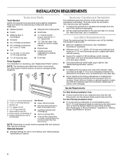
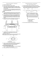
... Standard fittings for wood studs. Special Requirements For Wall Venting Installation Only: ■■ Cutout must provide: ■■ Minimum installation dimensions. A B C D E FG H A. Washers (2) D. Z\v" x 2" lag screws (2) F. Sheet metal screws (2) G. The piece inside... upper cabinet. Location Requirements Check the opening . ■■ Support for cooking. See "Installation Dimensions" illustration. ■■ Minimum one 2" x 4" (50.8 x 101.6 mm) wood wall stud and minimum C\," (10 ...
... Standard fittings for wood studs. Special Requirements For Wall Venting Installation Only: ■■ Cutout must provide: ■■ Minimum installation dimensions. A B C D E FG H A. Washers (2) D. Z\v" x 2" lag screws (2) F. Sheet metal screws (2) G. The piece inside... upper cabinet. Location Requirements Check the opening . ■■ Support for cooking. See "Installation Dimensions" illustration. ■■ Minimum one 2" x 4" (50.8 x 101.6 mm) wood wall stud and minimum C\," (10 ...
Installation Guide
Page 3
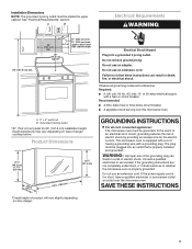
.... Do not remove ground prong. Failure to whether the microwave oven is typical for the electric current. A. 2" x 4" wall stud B. Product Dimensions 17¹⁄₈" (43.5 cm) (0.5 cm) 16¹⁄₄" (41.3 cm) (42.15U6c³p⁄m₄t"o)* 29⁷⁄...cabinet. Grounded 3 prong outlet *30" (76.2 cm) is properly grounded. Do not use an extension cord. SAVE THESE INSTRUCTIONS 3 Installation Dimensions NOTE: The grounded 3 prong outlet must be plugged into a grounded 3 prong outlet. or 20-amp electrical supply with a grounding plug. ...
.... Do not remove ground prong. Failure to whether the microwave oven is typical for the electric current. A. 2" x 4" wall stud B. Product Dimensions 17¹⁄₈" (43.5 cm) (0.5 cm) 16¹⁄₄" (41.3 cm) (42.15U6c³p⁄m₄t"o)* 29⁷⁄...cabinet. Grounded 3 prong outlet *30" (76.2 cm) is properly grounded. Do not use an extension cord. SAVE THESE INSTRUCTIONS 3 Installation Dimensions NOTE: The grounded 3 prong outlet must be plugged into a grounded 3 prong outlet. or 20-amp electrical supply with a grounding plug. ...
Installation Guide
Page 6
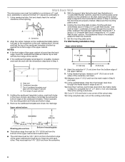
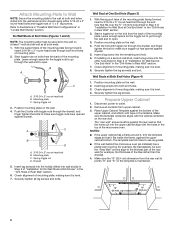
... Wall Stud(s)," and mark at least 1, preferably 2 hole(s) through the marks made in steps 8 and 10. 12. D A C B A. Top of cardboard template must align with the dimensions described in one corner of cabinet. Measure down 4" (10.2 cm) from the bottom edge of the cardboard template is aligned to the wall stud centerline...
... Wall Stud(s)," and mark at least 1, preferably 2 hole(s) through the marks made in steps 8 and 10. 12. D A C B A. Top of cardboard template must align with the dimensions described in one corner of cabinet. Measure down 4" (10.2 cm) from the bottom edge of the cardboard template is aligned to the wall stud centerline...
Installation Guide
Page 8
... the rear wall so that it , trim the template edges so that the holes cut out the rectangular area. 8 Make sure the 10" (25.4 cm) dimension from upper cabinet. 3. For Roof Venting Installation Only: 7. The "rear wall" arrows must be sure the "Rear Wall" arrows align to the thickest part of...
... the rear wall so that it , trim the template edges so that the holes cut out the rectangular area. 8 Make sure the 10" (25.4 cm) dimension from upper cabinet. 3. For Roof Venting Installation Only: 7. The "rear wall" arrows must be sure the "Rear Wall" arrows align to the thickest part of...

Dimension Guide
Page 1
...microwave oven. Specifications subject to change without notice. W10823831A 06/30/2016 See "Electrical Requirements" section. A. 2" x 4" wall stud B. Because Whirlpool Corporation includes a continuous commitment to improve our products, we reserve the right to change materials and specifications without notice. Ref. A B 30"...(76.2 cm) min. 30" (76.2 cm) typical* 12" (30.5 cm) min. 14" (35.6 cm) max. Exact dimensions may vary depending on type of product will vary slightly depending on door design. or 20-amp electrical supply with product. For complete details, ...
...microwave oven. Specifications subject to change without notice. W10823831A 06/30/2016 See "Electrical Requirements" section. A. 2" x 4" wall stud B. Because Whirlpool Corporation includes a continuous commitment to improve our products, we reserve the right to change materials and specifications without notice. Ref. A B 30"...(76.2 cm) min. 30" (76.2 cm) typical* 12" (30.5 cm) min. 14" (35.6 cm) max. Exact dimensions may vary depending on type of product will vary slightly depending on door design. or 20-amp electrical supply with product. For complete details, ...

Installation Guide
Page 1
... This product is suitable for further notes. Table of Contents MICROWAVE HOOD COMBINATION SAFETY 1 INSTALLATION REQUIREMENTS 2 Tools and Parts 2 Remove Cardboard Template 2 Location Requirements 2 Product Dimensions 3 Electrical Requirements 3 INSTALLATION INSTRUCTIONS 4 Remove Mounting Plate 4 Rotate Blower Motor 4 Locate Wall Stud(s 6 Mark Rear Wall 7 Drill Holes in Rear Wall 7 Attach Mounting Plate to...
... This product is suitable for further notes. Table of Contents MICROWAVE HOOD COMBINATION SAFETY 1 INSTALLATION REQUIREMENTS 2 Tools and Parts 2 Remove Cardboard Template 2 Location Requirements 2 Product Dimensions 3 Electrical Requirements 3 INSTALLATION INSTRUCTIONS 4 Remove Mounting Plate 4 Rotate Blower Motor 4 Locate Wall Stud(s 6 Mark Rear Wall 7 Drill Holes in Rear Wall 7 Attach Mounting Plate to...

Installation Guide
Page 2
..." section. Special Requirements For Wall Venting Installation Only: ■■ Cutout must provide: ■■ Minimum installation dimensions. NOTE: The hardware items listed here are not designed to Round Transition" illustration in "Venting Design Specifications" section. 2 Washers (2) D. ...See "Installation Dimensions" illustration. ■■ Minimum one 2" x 4" (50.8 x 101.6 mm) wood wall stud and minimum C\," (10 mm)...
..." section. Special Requirements For Wall Venting Installation Only: ■■ Cutout must provide: ■■ Minimum installation dimensions. NOTE: The hardware items listed here are not designed to Round Transition" illustration in "Venting Design Specifications" section. 2 Washers (2) D. ...See "Installation Dimensions" illustration. ■■ Minimum one 2" x 4" (50.8 x 101.6 mm) wood wall stud and minimum C\," (10 mm)...

Installation Guide
Page 3
...9632;■ A time-delay fuse or time-delay circuit breaker. ■■ A separate circuit serving only this microwave oven. Exact dimensions may vary depending on door design. GROUNDING INSTRUCTIONS I For all governing codes and ordinances. The microwave oven is properly installed and grounded. ...in death, fire, or electrical shock. If the power supply cord is properly grounded. Do not use an adapter. Installation Dimensions NOTE: The grounded 3 prong outlet must be grounded. Observe all cord connected appliances: The microwave oven must be plugged into a ...
...9632;■ A time-delay fuse or time-delay circuit breaker. ■■ A separate circuit serving only this microwave oven. Exact dimensions may vary depending on door design. GROUNDING INSTRUCTIONS I For all governing codes and ordinances. The microwave oven is properly installed and grounded. ...in death, fire, or electrical shock. If the power supply cord is properly grounded. Do not use an adapter. Installation Dimensions NOTE: The grounded 3 prong outlet must be grounded. Observe all cord connected appliances: The microwave oven must be plugged into a ...

Installation Guide
Page 7
... of 1 wall stud, preferably 2, using a minimum of the cardboard template is over wall studs, use 2 lag screws. Top of cardboard template must align with the dimensions described in Step 3, and that the top of 1 lag screw, preferably 2. 1. Remove the cardboard template and check the markings: Upper cabinet bottom 15³⁄...
... of 1 wall stud, preferably 2, using a minimum of the cardboard template is over wall studs, use 2 lag screws. Top of cardboard template must align with the dimensions described in Step 3, and that the top of 1 lag screw, preferably 2. 1. Remove the cardboard template and check the markings: Upper cabinet bottom 15³⁄...
Installation Guide
Page 8
.... Disconnect power to use as guides. ■■ If the wall behind the microwave oven (as at both ends. 1. Make sure the 10" (25.4 cm) dimension from the rear wall to points "D" and "E" on bolts from the back of the mounting plate facing forward, insert a 3/16-24 x 3" round-head bolt through...
.... Disconnect power to use as guides. ■■ If the wall behind the microwave oven (as at both ends. 1. Make sure the 10" (25.4 cm) dimension from the rear wall to points "D" and "E" on bolts from the back of the mounting plate facing forward, insert a 3/16-24 x 3" round-head bolt through...


