
Installation Instructions
Page 2
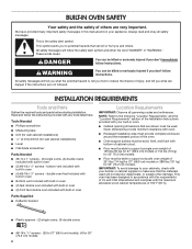
... (for wall cabinet installations) ■■ Level ■■ Flat-blade screwdriver Parts Needed ■■ #8-14 x 1" screws - (2) single ovens, (4) double ovens included with built-in oven ■■ (2) front feet double oven included with any tools listed here. double oven feet included with built-in oven ■■ Bottom vent included with built-in oven ■■ (2) feet double oven included with built-in oven ■■ (4) #8-18 x 3/8" screws - All safety messages will follow instructions...
... (for wall cabinet installations) ■■ Level ■■ Flat-blade screwdriver Parts Needed ■■ #8-14 x 1" screws - (2) single ovens, (4) double ovens included with built-in oven ■■ (2) front feet double oven included with any tools listed here. double oven feet included with built-in oven ■■ Bottom vent included with built-in oven ■■ (2) feet double oven included with built-in oven ■■ (4) #8-18 x 3/8" screws - All safety messages will follow instructions...

Installation Instructions
Page 3
..." (63.5 cm) minimum depth of the cutout* H. Single Ovens, Flush Installations A 25" (63.5 cm) minimum cutout depth is required. Recommended junction box location B. 3/4" (19 mm) top cleat* C. 271/4" (69.2 cm) minimum width of flush inset cutout D. 257/8" (65.7 cm) minimum width of opening E. 291/4" (74.3 cm) minimum height of flush inset cutout F. 281/2" (72.4 cm) recommended cutout height G. 11/16" (17 mm) side cleat...
..." (63.5 cm) minimum depth of the cutout* H. Single Ovens, Flush Installations A 25" (63.5 cm) minimum cutout depth is required. Recommended junction box location B. 3/4" (19 mm) top cleat* C. 271/4" (69.2 cm) minimum width of flush inset cutout D. 257/8" (65.7 cm) minimum width of opening E. 291/4" (74.3 cm) minimum height of flush inset cutout F. 281/2" (72.4 cm) recommended cutout height G. 11/16" (17 mm) side cleat...

Installation Instructions
Page 4
... Installations A 253/8" (64.4 cm) minimum cutout depth is required. Double Ovens Installed in a 1/4" (6 mm) reveal on the top, a 1/4" (6 mm) reveal on the sides, and a 1/8" (3 mm) reveal on the bottom of the cabinet. 4 Cabinet Dimensions - Flush Installations A B C D E F F G G H H J I Front View 27" (68.6 cm) Models A. 9/16" (14 mm) top cleat* B. 271/4" (69.2 cm) minimum width of flush inset cutout C. 257/8" (65.7 cm) minimum width of opening...
... Installations A 253/8" (64.4 cm) minimum cutout depth is required. Double Ovens Installed in a 1/4" (6 mm) reveal on the top, a 1/4" (6 mm) reveal on the sides, and a 1/8" (3 mm) reveal on the bottom of the cabinet. 4 Cabinet Dimensions - Flush Installations A B C D E F F G G H H J I Front View 27" (68.6 cm) Models A. 9/16" (14 mm) top cleat* B. 271/4" (69.2 cm) minimum width of flush inset cutout C. 257/8" (65.7 cm) minimum width of opening...

Installation Instructions
Page 5
... Requirements" section, and complete the instructions in oven. 1. Set the oven door(s) aside on the final location for installation. 4. A Oven door hinge lock in back or other materials that may need to the following "Installation Instructions" and the "Installation Instructions" section of the Installation Instructions provided with the oven door resting on select models B. INSTALLATION INSTRUCTIONS Prepare Built-In Oven 4. The door will not remove properly. NOTES: ■■ Refer to gently shift door from the oven. WARNING Excessive Weight Hazard Use...
... Requirements" section, and complete the instructions in oven. 1. Set the oven door(s) aside on the final location for installation. 4. A Oven door hinge lock in back or other materials that may need to the following "Installation Instructions" and the "Installation Instructions" section of the Installation Instructions provided with the oven door resting on select models B. INSTALLATION INSTRUCTIONS Prepare Built-In Oven 4. The door will not remove properly. NOTES: ■■ Refer to gently shift door from the oven. WARNING Excessive Weight Hazard Use...

Installation Instructions
Page 6
... locked position. Replace Oven Door(s) 1. When the hinges are properly installed and the door closed, there should be installed in oven. Double Ovens The oven feet need to be installed to allow a double oven to be installed in the oven cavity for door hinge lock 3. A. If one side of the oven door is engaged in the corners of the oven cavity. NOTE: Do not remove the spacers. 4. Lower the oven door to the fully open to the "Make Electrical Connection...
... locked position. Replace Oven Door(s) 1. When the hinges are properly installed and the door closed, there should be installed in oven. Double Ovens The oven feet need to be installed to allow a double oven to be installed in the oven cavity for door hinge lock 3. A. If one side of the oven door is engaged in the corners of the oven cavity. NOTE: Do not remove the spacers. 4. Lower the oven door to the fully open to the "Make Electrical Connection...

Installation Instructions
Page 7
... side of the oven. 2. Replace Plastic Spacers Replace Plastic Spacers on the right front of the oven. Remove the screw attaching the plastic spacer (A) to the "Make Electrical Connection" section in its back on the left front spacer using a #8-18 x 3/8" screw. Plastic spacer B. In the same manner, install a front foot on Single Ovens 1. Using 2 or more people, place the oven on its upright...
... side of the oven. 2. Replace Plastic Spacers Replace Plastic Spacers on the right front of the oven. Remove the screw attaching the plastic spacer (A) to the "Make Electrical Connection" section in its back on the left front spacer using a #8-18 x 3/8" screw. Plastic spacer B. In the same manner, install a front foot on Single Ovens 1. Using 2 or more people, place the oven on its upright...

Installation Instructions
Page 8
... 3. Remove the tape from the black front trim piece. ■■ Securely fasten the oven to push oven into the cabinet cutout. B A A. Using 2 or more people, lift the oven partially into cabinet. A 2. Push microwave oven completely into the cabinet, open the microwave oven door and push against the outside edges. Oven frame B. NOTE: When pushing the microwave oven into cabinet and center in the black trim piece, aligning with this kit. Push...
... 3. Remove the tape from the black front trim piece. ■■ Securely fasten the oven to push oven into the cabinet cutout. B A A. Using 2 or more people, lift the oven partially into cabinet. A 2. Push microwave oven completely into the cabinet, open the microwave oven door and push against the outside edges. Oven frame B. NOTE: When pushing the microwave oven into cabinet and center in the black trim piece, aligning with this kit. Push...

Installation Instructions
Page 9
... use when a single or double built-in oven is not, repeat the removal and installation procedures. Some force may also be required to see which step was skipped. 2. Deflector bracket E. #8-18 x 3/8" screw 5. If there is connected. ■■ See the "Troubleshooting" section in the Use and Care Guide. 7. For oven use , set up the language, clock, and any other preferences if available. Align vent tab (B) with your oven. The display panel will light...
... use when a single or double built-in oven is not, repeat the removal and installation procedures. Some force may also be required to see which step was skipped. 2. Deflector bracket E. #8-18 x 3/8" screw 5. If there is connected. ■■ See the "Troubleshooting" section in the Use and Care Guide. 7. For oven use , set up the language, clock, and any other preferences if available. Align vent tab (B) with your oven. The display panel will light...


