
User Manual
Page 2
..., and tell you to rear range foot. This symbol alerts you what the potential hazard is, tell you how to reduce the chance of others . This is moved. All safety messages will follow these instructions can happen if the instructions are very important. Connect anti-tip bracket to potential hazards that can tip the range and be killed or seriously...
..., and tell you to rear range foot. This symbol alerts you what the potential hazard is, tell you how to reduce the chance of others . This is moved. All safety messages will follow these instructions can happen if the instructions are very important. Connect anti-tip bracket to potential hazards that can tip the range and be killed or seriously...
User Manual
Page 3
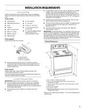
... located on the model/serial rating plate. Product Dimensions B C A. Anti-tip bracket B. If cabinet storage is required. IMPORTANT: To avoid damage to your cabinets, check with the maximum allowable wood cabinet temperatures of burns or fire by a licensed, qualified electrical installer. Longer screws are included. Model/serial rating plate (located on the left side frame behind the storage drawer panel. ■ The range should be made by reaching over heated surface...
... located on the model/serial rating plate. Product Dimensions B C A. Anti-tip bracket B. If cabinet storage is required. IMPORTANT: To avoid damage to your cabinets, check with the maximum allowable wood cabinet temperatures of burns or fire by a licensed, qualified electrical installer. Longer screws are included. Model/serial rating plate (located on the left side frame behind the storage drawer panel. ■ The range should be made by reaching over heated surface...
User Manual
Page 4
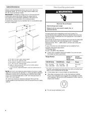
... height. A C B Electrical Requirements WARNING Electrical Shock Hazard Electrically ground range. opening width C. Range Rating* Rating of Circuit Power Protection Supply Cord 120/240 Volts 120/208 Volts Amps Amps 8.8 - 16.5 KW 7.8 - 12.5 KW 40 16.6 - 22.5 KW 12.6 - 18.5 KW 50 40 or 50 50 *The NEC calculated load is less than the total connected load listed on the model/serial rating plate. ■ A time-delay fuse or circuit breaker is...
... height. A C B Electrical Requirements WARNING Electrical Shock Hazard Electrically ground range. opening width C. Range Rating* Rating of Circuit Power Protection Supply Cord 120/240 Volts 120/208 Volts Amps Amps 8.8 - 16.5 KW 7.8 - 12.5 KW 40 16.6 - 22.5 KW 12.6 - 18.5 KW 50 40 or 50 50 *The NEC calculated load is less than the total connected load listed on the model/serial rating plate. ■ A time-delay fuse or circuit breaker is...
User Manual
Page 5
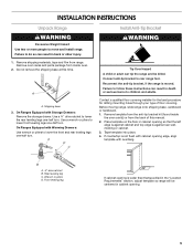
... opening so that specified in the "Location Requirements" section, adjust template so range will be killed. Failure to do so can result in death or serious burns to lower the front and rear leveling legs one-half turn . A D C Install Anti-Tip Bracket WARNING Tip Over Hazard A child or adult can result in back or other injury. 1. Failure to rear range foot. Tape template into place. 4. INSTALLATION INSTRUCTIONS...
... opening so that specified in the "Location Requirements" section, adjust template so range will be killed. Failure to do so can result in death or serious burns to lower the front and rear leveling legs one-half turn . A D C Install Anti-Tip Bracket WARNING Tip Over Hazard A child or adult can result in back or other injury. 1. Failure to rear range foot. Tape template into place. 4. INSTALLATION INSTRUCTIONS...
User Manual
Page 6
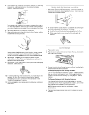
... final electrical connection. Level Range 1. Push range back into position. Push range back into position. Pull drawer open to back. 3. Remove drawer and set it conforms to the subfloor. Depending on a covered surface. then front to first stop position. Check that rear leveling leg is level. On Ranges Equipped with Warming Drawers: Use channel lock pliers to adjust leveling legs up or down until range is engaged in drawer guides. 5. Verify Anti-Tip Bracket Location 1. Place level on some models). 6 Check that rear leveling...
... final electrical connection. Level Range 1. Push range back into position. Push range back into position. Pull drawer open to back. 3. Remove drawer and set it conforms to the subfloor. Depending on a covered surface. then front to first stop position. Check that rear leveling leg is level. On Ranges Equipped with Warming Drawers: Use channel lock pliers to adjust leveling legs up or down until range is engaged in drawer guides. 5. Verify Anti-Tip Bracket Location 1. Place level on some models). 6 Check that rear leveling...
User Manual
Page 7
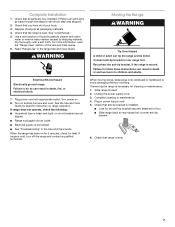
... the range is level. When the range has been on range operation. Unplug the power supply cord. 3. Check that you have all packaging materials. 4. Check that anti-tip bracket is installed: ■ Look for cleaning or maintenance: 1. Check that the range is moved. Failure to rear range foot. Turn on . 8. Electrical Shock Hazard Electrically ground range. Complete cleaning or maintenance. 4. Connect anti-tip bracket to do so can tip the range and be killed. Complete Installation 1. Turn power on surface burners and oven.
... the range is level. When the range has been on range operation. Unplug the power supply cord. 3. Check that you have all packaging materials. 4. Check that anti-tip bracket is installed: ■ Look for cleaning or maintenance: 1. Check that the range is moved. Failure to rear range foot. Turn on . 8. Electrical Shock Hazard Electrically ground range. Complete cleaning or maintenance. 4. Connect anti-tip bracket to do so can tip the range and be killed. Complete Installation 1. Turn power on surface burners and oven.


