
Service Manual
Page 13
Duplex Unit 1 - 8 Front Panel Configuration 1 - 9 Front Panel LED indicators 1 - 9 Image Processor (IP) Board Components 1 - 10 Rear Panel Configuration of the Printer 1 - 6 Print Engine Base Configuration 1 - 6 Printer Options - Print Engine 1 - 13 Physical Dimensions - Options 1 - 13 Printer ...Contents xi Lower Tray Deck (LTD) and Lower Tray Assembly (LTA 1 - 7 Printer Options (cont'd) - Table of Contents General Information 1 - 1 The Phaser 7300 Color Printer Overview 1 - 2 Phaser 7300 Printer Configurations 1 - 3 Printer Memory and RAM Capabilities 1 - 5 Parts of the...
Duplex Unit 1 - 8 Front Panel Configuration 1 - 9 Front Panel LED indicators 1 - 9 Image Processor (IP) Board Components 1 - 10 Rear Panel Configuration of the Printer 1 - 6 Print Engine Base Configuration 1 - 6 Printer Options - Print Engine 1 - 13 Physical Dimensions - Options 1 - 13 Printer ...Contents xi Lower Tray Deck (LTD) and Lower Tray Assembly (LTA 1 - 7 Printer Options (cont'd) - Table of Contents General Information 1 - 1 The Phaser 7300 Color Printer Overview 1 - 2 Phaser 7300 Printer Configurations 1 - 3 Printer Memory and RAM Capabilities 1 - 5 Parts of the...
Service Manual
Page 15
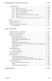
...Duplex Unit 8 - 234 Paper Jam Detection 8 - 235 Paper Size Sensing 8 - 236 Fuser Temperature Settings 8 - 237 Cover Open Detection 8 - 238 Toner Detection 8 - 239 Color Registration Detection 8 - 241 Customer Replaceable Consumable Detection 8 - 242 Customer Replaceable Consumable (CRC) Life Counter Behavior ..........8 - 242 Printer... Tray Assembly (Trays 2, 3, 4, 5) .....7 - 208 Kits...7 - 210 Supplies and Accessories 7 - 213 Manuals and CD's 7 - 213 Customer Replaceable Consumables 7 - 214 Paper and Media 7 - 215 Theory of Operation 8 - 219 Mechanical Process of the Printer 8 ...
...Duplex Unit 8 - 234 Paper Jam Detection 8 - 235 Paper Size Sensing 8 - 236 Fuser Temperature Settings 8 - 237 Cover Open Detection 8 - 238 Toner Detection 8 - 239 Color Registration Detection 8 - 241 Customer Replaceable Consumable Detection 8 - 242 Customer Replaceable Consumable (CRC) Life Counter Behavior ..........8 - 242 Printer... Tray Assembly (Trays 2, 3, 4, 5) .....7 - 208 Kits...7 - 210 Supplies and Accessories 7 - 213 Manuals and CD's 7 - 213 Customer Replaceable Consumables 7 - 214 Paper and Media 7 - 215 Theory of Operation 8 - 219 Mechanical Process of the Printer 8 ...

Service Manual
Page 17
... Printing 1 - 4 Power Saver Mode...1 - 4 Printer Memory and RAM Capabilities 1 - 5 Parts of the Printer ...1 - 6 Print Engine Base Configuration 1 - 6 Printer Options - General Information The Xerox Phaser® 7300 Color Printer Service Manual is the primary document used for repairing, maintaining, and troubleshooting the printer. Lower Tray Deck (LTD) and Lower Tray Assembly (LTA 1 - 7 Printer Options (cont'd) - Options 1 - 13 Printer Clearances ...1 - 13 Functional Specifications...
... Printing 1 - 4 Power Saver Mode...1 - 4 Printer Memory and RAM Capabilities 1 - 5 Parts of the Printer ...1 - 6 Print Engine Base Configuration 1 - 6 Printer Options - General Information The Xerox Phaser® 7300 Color Printer Service Manual is the primary document used for repairing, maintaining, and troubleshooting the printer. Lower Tray Deck (LTD) and Lower Tray Assembly (LTA 1 - 7 Printer Options (cont'd) - Options 1 - 13 Printer Clearances ...1 - 13 Functional Specifications...

Service Manual
Page 54
... diagnostics to step [11]. wiring harness. 8 Use service diagnostics to test the Go to step [10]. Exit Gate Solenoid (Duplex) Face-up Solenoid (Top-Side Output) Do the solenoids operate correctly? 9 Visually inspect the Registration Rollers Replace the Go to step...Fuser Motor Replace the Engine Controller Board. interfere with normal operation. sensor. and/or the problem motor/clutch. 2-38 Phaser 7300 Color Printer Service Manual Assembly. Troubleshooting Procedure Table (cont'd.) Steps Actions and Questions Yes No 6 Check the sensor for each motor Replace the ...
... diagnostics to step [11]. wiring harness. 8 Use service diagnostics to test the Go to step [10]. Exit Gate Solenoid (Duplex) Face-up Solenoid (Top-Side Output) Do the solenoids operate correctly? 9 Visually inspect the Registration Rollers Replace the Go to step...Fuser Motor Replace the Engine Controller Board. interfere with normal operation. sensor. and/or the problem motor/clutch. 2-38 Phaser 7300 Color Printer Service Manual Assembly. Troubleshooting Procedure Table (cont'd.) Steps Actions and Questions Yes No 6 Check the sensor for each motor Replace the ...
Service Manual
Page 55
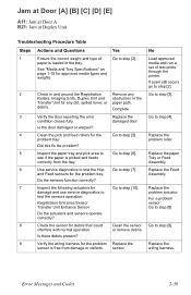
... problem Replace the Replace the sensor is picked and feeds Tray or Feed correctly from damage or defects. interfere with normal operation. Assembly. Is there debris present? 9 Verify the wiring harness for debris that could Clean the sensor Go to step [10]. Complete ... at Door [A] [B] [C] [D] [E] A11: Jam at Door A B21: Jam at Duplex Unit Troubleshooting Procedure Table Steps Actions and Questions Yes No 1 Ensure the correct weight and type of test prints through the printer. or remove debris. Did this fix the problem? 5 Inspect the paper tray and pick...
... problem Replace the Replace the sensor is picked and feeds Tray or Feed correctly from damage or defects. interfere with normal operation. Assembly. Is there debris present? 9 Verify the wiring harness for debris that could Clean the sensor Go to step [10]. Complete ... at Door [A] [B] [C] [D] [E] A11: Jam at Door A B21: Jam at Duplex Unit Troubleshooting Procedure Table Steps Actions and Questions Yes No 1 Ensure the correct weight and type of test prints through the printer. or remove debris. Did this fix the problem? 5 Inspect the paper tray and pick...

Service Manual
Page 56
...Board. go to the LTA Controller problem Tray. Assembly for the Check the wiring to step [11...defects? 12 Use service diagnostics to test the Duplex Go to step [12]. Unit motor and...to step [12]. Board. Board for the Duplex Replace the Unit. Go to step [17].... and free from damage or defects. Assembly for the problem Go to Replace the... the LTA Is the wiring free from defects? Duplex Unit. Registration Motor and Registration Clutch. harness, ...Roller the grounding strap is free from defects? Assembly. Controller Board. Is the wiring harness properly ...
...Board. go to the LTA Controller problem Tray. Assembly for the Check the wiring to step [11...defects? 12 Use service diagnostics to test the Duplex Go to step [12]. Unit motor and...to step [12]. Board. Board for the Duplex Replace the Unit. Go to step [17].... and free from damage or defects. Assembly for the problem Go to Replace the... the LTA Is the wiring free from defects? Duplex Unit. Registration Motor and Registration Clutch. harness, ...Roller the grounding strap is free from defects? Assembly. Controller Board. Is the wiring harness properly ...

Service Manual
Page 80
...Verify the correct Phaser 7300 Duplex Unit is installed. 2 Check that the Duplex Unit is installed in the printer. Reseat the Duplex Unit Unsupported Tray [2] [3] [4] [5] ROM Failure U35: Tray 2 U36: Tray 3 U37: Tray 4 U38: Tray 5 Note: The printer has detected an incompatible LTA or LTD assembly. Troubleshooting Procedure... in the following order: LTA Controller Board Engine Controller Board No Replace the tray. 2-64 Phaser 7300 Color Printer Service Manual Is the correct Fuser installed? No Replace the Duplex Unit. Yes Go to step [2]. Replace in the following order...
...Verify the correct Phaser 7300 Duplex Unit is installed. 2 Check that the Duplex Unit is installed in the printer. Reseat the Duplex Unit Unsupported Tray [2] [3] [4] [5] ROM Failure U35: Tray 2 U36: Tray 3 U37: Tray 4 U38: Tray 5 Note: The printer has detected an incompatible LTA or LTD assembly. Troubleshooting Procedure... in the following order: LTA Controller Board Engine Controller Board No Replace the tray. 2-64 Phaser 7300 Color Printer Service Manual Is the correct Fuser installed? No Replace the Duplex Unit. Yes Go to step [2]. Replace in the following order...

Service Manual
Page 145
...(PL 4.16 6 - 150 Toner Sensor Board (PL 4.19 6 - 152 Toner Cartridge Sensor Actuators (PL 4.18 6 - 153 Duplex Unit Assembly (PL 1.15 6 - 154 Front Chassis Fan (PL 5.2.4 6 - 155 Printer Unit Chassis (PL 5.1.14 6 - 156 Rear Power Supply Fan (PL 5.1.31 6 - 162 Entrance Sensor Board (PL 5.1.17 ... Actuator (PL 5.1.18 6 - 171 Top/Side Output Solenoid (PL 5.1.6) and Duplex Gate Solenoid (PL 5.1.8 6 - 172 Registration Clutch (PL 5.1.20 6 - 173 FRU Disassembly 6-129 Contents Orientation of the printer according to the Field Replaceable Units (FRUs) Parts List. In some instances, the...
...(PL 4.16 6 - 150 Toner Sensor Board (PL 4.19 6 - 152 Toner Cartridge Sensor Actuators (PL 4.18 6 - 153 Duplex Unit Assembly (PL 1.15 6 - 154 Front Chassis Fan (PL 5.2.4 6 - 155 Printer Unit Chassis (PL 5.1.14 6 - 156 Rear Power Supply Fan (PL 5.1.31 6 - 162 Entrance Sensor Board (PL 5.1.17 ... Actuator (PL 5.1.18 6 - 171 Top/Side Output Solenoid (PL 5.1.6) and Duplex Gate Solenoid (PL 5.1.8 6 - 172 Registration Clutch (PL 5.1.20 6 - 173 FRU Disassembly 6-129 Contents Orientation of the printer according to the Field Replaceable Units (FRUs) Parts List. In some instances, the...

Service Manual
Page 146
... 5.2.13 6 - 186 Transfer Unit and Fuser Motor Assembly (PL 5.2.2 6 - 187 Color Registration Plate Shutter (PL 5.1.11 6 - 188 Color Registration Sensor Assembly (PL 5.1.10 6 - 189 Color Registration Shutter Solenoid (PL 5.1.13 6 - 190 LED Head 600 dpi (PL 4.9a) and LED Head Holder (PL 4.9b 6 - 191 (Imaging Unit) Drum Contact Assembly (PL 5.1.27 6 - 192 6-130 Phaser 7300 Color Printer Service Manual
... 5.2.13 6 - 186 Transfer Unit and Fuser Motor Assembly (PL 5.2.2 6 - 187 Color Registration Plate Shutter (PL 5.1.11 6 - 188 Color Registration Sensor Assembly (PL 5.1.10 6 - 189 Color Registration Shutter Solenoid (PL 5.1.13 6 - 190 LED Head 600 dpi (PL 4.9a) and LED Head Holder (PL 4.9b 6 - 191 (Imaging Unit) Drum Contact Assembly (PL 5.1.27 6 - 192 6-130 Phaser 7300 Color Printer Service Manual

Service Manual
Page 170
...(next to the guide pin) and pull forward to the locked position when seated properly. 6-154 Phaser 7300 Color Printer Service Manual The release lever will snap back to release the Duplex Unit from the paper tray. 7300-188 Reassembly 1. Align the guide pins carefully then push down... on the guide pins to separate it from Tray 1. 3. Holding tray 1, force the duplex unit backwards about 5 cm and lift the duplex unit to lock the Duplex unit in place. Duplex Unit Assembly (PL 1.15) Note: The Duplex Unit and Tray 1 are interlocked. 1.
...(next to the guide pin) and pull forward to the locked position when seated properly. 6-154 Phaser 7300 Color Printer Service Manual The release lever will snap back to release the Duplex Unit from the paper tray. 7300-188 Reassembly 1. Align the guide pins carefully then push down... on the guide pins to separate it from Tray 1. 3. Holding tray 1, force the duplex unit backwards about 5 cm and lift the duplex unit to lock the Duplex unit in place. Duplex Unit Assembly (PL 1.15) Note: The Duplex Unit and Tray 1 are interlocked. 1.

Service Manual
Page 195
FRU Disassembly S7300-165 6-179 Note: Be careful not to lose the springs when removing the Duplex Guide Assembly. Duplex Guide Assembly (PL 5.1.2) 1. Leave the springs in the printer. . Grasp the Duplex Guide Assembly and pull the assembly straight up and out of the printer.
FRU Disassembly S7300-165 6-179 Note: Be careful not to lose the springs when removing the Duplex Guide Assembly. Duplex Guide Assembly (PL 5.1.2) 1. Leave the springs in the printer. . Grasp the Duplex Guide Assembly and pull the assembly straight up and out of the printer.

Service Manual
Page 198
Slide the Fuser Exit Roller to the rear of the printer until the front end of the Fuser Exit Roller (item #2), remove 1 G screw securing the ground contact (item #3). 8. Fuser Exit Roller (PL 5.1.1) 1. Remove the Front Chassis ... Electrical Card Cage (see pg. 6-146). 3. At the rear of the shaft is free, and remove the shaft. 1 2 3 G B S7300-167 6-182 Phaser 7300 Color Printer Service Manual Lift and remove the Duplex Guide Assembly (see pg. 6-162). 4. Remove the bearing, 1 B screw, and the fuser drive gear. 9. Remove the Rear Power Supply Fan and Duct (see...
Slide the Fuser Exit Roller to the rear of the printer until the front end of the Fuser Exit Roller (item #2), remove 1 G screw securing the ground contact (item #3). 8. Fuser Exit Roller (PL 5.1.1) 1. Remove the Front Chassis ... Electrical Card Cage (see pg. 6-146). 3. At the rear of the shaft is free, and remove the shaft. 1 2 3 G B S7300-167 6-182 Phaser 7300 Color Printer Service Manual Lift and remove the Duplex Guide Assembly (see pg. 6-162). 4. Remove the bearing, 1 B screw, and the fuser drive gear. 9. Remove the Rear Power Supply Fan and Duct (see...

Service Manual
Page 199
From the Engine Controller Board, remove the connector to the Fuser Exit Sensor Assembly (PARTTEMP). 4. FRU Disassembly S7300-76 6-183 Lift and remove the Duplex Exit Gate. 5. Guide the sensor wiring harness through the chassis as you remove the assembly. Remove the Print Unit Chassis (see pg. 6-182). 2. Remove 1 B screw securing the Fuser Exit Sensor Assembly. 6. Fuser Exit Sensor Assembly (PL 5.1.3) 1. Remove the Fuser Exit Roller (see pg. 6-156). 3.
From the Engine Controller Board, remove the connector to the Fuser Exit Sensor Assembly (PARTTEMP). 4. FRU Disassembly S7300-76 6-183 Lift and remove the Duplex Exit Gate. 5. Guide the sensor wiring harness through the chassis as you remove the assembly. Remove the Print Unit Chassis (see pg. 6-182). 2. Remove 1 B screw securing the Fuser Exit Sensor Assembly. 6. Fuser Exit Sensor Assembly (PL 5.1.3) 1. Remove the Fuser Exit Roller (see pg. 6-156). 3.

Service Manual
Page 211
Front Top Cover Hinge Shaft Top Cover Hinge Spring - Covers No. Rear Top Cover Damper - Front Front Cover Duplex Slot Cover Top Cover Damper - Part Number Qty 1 116-0998-00 1 2 116-1061-00 2 3 116-1083-00 1 4 116-1006-00 1 5 116-1051-00 1 6 116-...Cover Side Output Tray Links Side Output Tray Left Side Cover Top Cover Hinge Spring - FRU Parts List 1.0 - Rear Rear Cover MPT Pick Assembly (PL 2.0) Front PS Fan Duplex Transport Assembly Universal Paper Tray 1 (PL 6.0) Top Fuser Fan Duct Foot Right Side Cover (Door A) Top Fuser Cooling Fan MPT Top Cover Temperature/...
Front Top Cover Hinge Shaft Top Cover Hinge Spring - Covers No. Rear Top Cover Damper - Front Front Cover Duplex Slot Cover Top Cover Damper - Part Number Qty 1 116-0998-00 1 2 116-1061-00 2 3 116-1083-00 1 4 116-1006-00 1 5 116-1051-00 1 6 116-...Cover Side Output Tray Links Side Output Tray Left Side Cover Top Cover Hinge Spring - FRU Parts List 1.0 - Rear Rear Cover MPT Pick Assembly (PL 2.0) Front PS Fan Duplex Transport Assembly Universal Paper Tray 1 (PL 6.0) Top Fuser Fan Duct Foot Right Side Cover (Door A) Top Fuser Cooling Fan MPT Top Cover Temperature/...
Service Manual
Page 219
.../Side Output Solenoid 1 Fuser Exit Roller Bushing (Front) 1 Duplex Gate Solenoid Assembly 1 Front Power Supply Fan 1 Color Registration Sensor Assembly (includes ADC Sensor) 1 Color Registration Plate Shutter (includes Color Chip for ADC and Tag number) 1 Registration Shutter Spring 1 Color Registration Shutter Solenoid 1 Printer Unit Chassis 1 Registration Entrance Sensor Actuator (B) 1 Registration Roller Assembly (B) 1 Entrance Sensor Board 1 Transfer Belt Entrance Sensor...
.../Side Output Solenoid 1 Fuser Exit Roller Bushing (Front) 1 Duplex Gate Solenoid Assembly 1 Front Power Supply Fan 1 Color Registration Sensor Assembly (includes ADC Sensor) 1 Color Registration Plate Shutter (includes Color Chip for ADC and Tag number) 1 Registration Shutter Spring 1 Color Registration Shutter Solenoid 1 Printer Unit Chassis 1 Registration Entrance Sensor Actuator (B) 1 Registration Roller Assembly (B) 1 Entrance Sensor Board 1 Transfer Belt Entrance Sensor...

Service Manual
Page 221
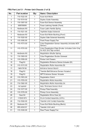
Printer Unit Chassis (2 of 2) and Power Supplies No. 1 2 3 4 5 6 7 8 9 10 11 12 13 Part number 003E55700 116-1556-00 116-1029-00 116-1215-00 116-1034-...-00 116-1064-00 Qty Description 1 Fuser Latching Handle (Rear) 1 Transfer Unit Motor Assembly 1 Front Plate Assembly 1 Front Chassis Fan 1 LVPS Insulator 1 Duplex Exit Paper Guide 1 HVPS Insulator Imaging Unit Contact Assembly (HV) 1 High Voltage Power Supply 1 High Voltage Harness 1 Back Plate Assembly w/Drive Gears 1 (115 VAC) Low Voltage Power Supply 1 (220 VAC) Low Voltage...
Printer Unit Chassis (2 of 2) and Power Supplies No. 1 2 3 4 5 6 7 8 9 10 11 12 13 Part number 003E55700 116-1556-00 116-1029-00 116-1215-00 116-1034-...-00 116-1064-00 Qty Description 1 Fuser Latching Handle (Rear) 1 Transfer Unit Motor Assembly 1 Front Plate Assembly 1 Front Chassis Fan 1 LVPS Insulator 1 Duplex Exit Paper Guide 1 HVPS Insulator Imaging Unit Contact Assembly (HV) 1 High Voltage Power Supply 1 High Voltage Harness 1 Back Plate Assembly w/Drive Gears 1 (115 VAC) Low Voltage Power Supply 1 (220 VAC) Low Voltage...

Study Guide
Page 15
... polished lens surface on the LED assemblies where light is used to steps 3 through 6 of the packing tape from the Top Cover. Remove the Tape and Shipping Restraints In this exercise. Remove Tape Remove all of the Phaser 7300 Color Printer Setup Poster to complete this exercise,...complete this exercise, you will remove the tape and shipping restraints. The available printer options include: ■ Hard Drive ■ RAM ■ Duplex Unit Please refer to the instruction sheets for the printer that were purchased separately, install them steady to hold them now. Install the...
... polished lens surface on the LED assemblies where light is used to steps 3 through 6 of the packing tape from the Top Cover. Remove the Tape and Shipping Restraints In this exercise. Remove Tape Remove all of the Phaser 7300 Color Printer Setup Poster to complete this exercise,...complete this exercise, you will remove the tape and shipping restraints. The available printer options include: ■ Hard Drive ■ RAM ■ Duplex Unit Please refer to the instruction sheets for the printer that were purchased separately, install them steady to hold them now. Install the...

Study Guide
Page 22
... Duplex Unit and 550 Sheet Feeder To test the Duplex Unit and the 550 Sheet Feeder, send a two-sided, multi-page print job. Use Color Corrections In this exercise, you will test the available printer options. page 18 PHASER 7300 SETUP WORKSHEET version 1.0 Test Printer ...printer's Front Panel using 4-color separation. Press Match - None Use when printing from the files\pdfs folder of a document. Print on Transparencies In this tray was previously configured for printing documents with the color correction setting used, and compare them to ensure the assemblies ...
... Duplex Unit and 550 Sheet Feeder To test the Duplex Unit and the 550 Sheet Feeder, send a two-sided, multi-page print job. Use Color Corrections In this exercise, you will test the available printer options. page 18 PHASER 7300 SETUP WORKSHEET version 1.0 Test Printer ...printer's Front Panel using 4-color separation. Press Match - None Use when printing from the files\pdfs folder of a document. Print on Transparencies In this tray was previously configured for printing documents with the color correction setting used, and compare them to ensure the assemblies ...

Study Guide
Page 34
... check for paper or scraps in the Fuser, the Duplex Gate Assembly, or in Sensor B13 Duplex Input Duplex Entry B21 B8 Duplex Exit Sensor Duplex Input Sensor Tray 1 Tray 2 Duplex Rear Sensor Tray 3 Tray 4 Tray 5 Misfeed from MPT B Registration Entrance Sensor Misfeed from Duplex Unit Misfeed from Tray 1 E1 Misfeed from Tray 2... Right Door A error messages: ■ Open the right door and remove any paper or scraps, especially the left side page 30 PHASER 7300 CARE WORKSHEET 0 Though there are numerous Error Codes, jams are labels for some jams can be misleading and confusing.
... check for paper or scraps in the Fuser, the Duplex Gate Assembly, or in Sensor B13 Duplex Input Duplex Entry B21 B8 Duplex Exit Sensor Duplex Input Sensor Tray 1 Tray 2 Duplex Rear Sensor Tray 3 Tray 4 Tray 5 Misfeed from MPT B Registration Entrance Sensor Misfeed from Duplex Unit Misfeed from Tray 1 E1 Misfeed from Tray 2... Right Door A error messages: ■ Open the right door and remove any paper or scraps, especially the left side page 30 PHASER 7300 CARE WORKSHEET 0 Though there are numerous Error Codes, jams are labels for some jams can be misleading and confusing.


