Service Manual
Page 15
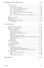
MPT Pick Assembly 7 - 196 PL 3.0 - Printer Unit Chassis (1 of the Imaging Units .8 - 232 Fuser and Paper Exit 8 - 233 Duplex Unit 8 - 234 Paper Jam Detection 8 - 235 Paper Size Sensing 8 - 236 Fuser Temperature Settings 8 - 237 Cover Open Detection 8 - 238 Toner Detection 8 - 239 Color Registration Detection 8 - 241 Customer Replaceable Consumable Detection 8 - 242 Customer Replaceable Consumable (CRC) Life Counter Behavior ..........8 - 242...
MPT Pick Assembly 7 - 196 PL 3.0 - Printer Unit Chassis (1 of the Imaging Units .8 - 232 Fuser and Paper Exit 8 - 233 Duplex Unit 8 - 234 Paper Jam Detection 8 - 235 Paper Size Sensing 8 - 236 Fuser Temperature Settings 8 - 237 Cover Open Detection 8 - 238 Toner Detection 8 - 239 Color Registration Detection 8 - 241 Customer Replaceable Consumable Detection 8 - 242 Customer Replaceable Consumable (CRC) Life Counter Behavior ..........8 - 242...

Service Manual
Page 37
... 4 Interface Failure Tray 5 Interface Failure Yellow LED Failure Magenta LED Failure Cyan LED Failure Black LED Failure Yellow Imaging Unit Failure Magenta Imaging Unit Failure Cyan Imaging Unit Failure Black Imaging Unit Failure Flash Hardware Failure Flash Software Failure Fuser Fan Failure Fuser 110v/220v Mismatch Failure Unsupported Duplex... Tray 4 ROM Unsupported Tray 5 ROM Fuse Cut Error in Fuser Fuse Cut Error in Transfer Unit Fuse Cut Error in Cyan Imaging Unit Fuse Cut Error in Magenta Imaging Unit Error Messages and Codes Usage Profile Code 136 137 138 139 140 141 143 142 144 145 ...
... 4 Interface Failure Tray 5 Interface Failure Yellow LED Failure Magenta LED Failure Cyan LED Failure Black LED Failure Yellow Imaging Unit Failure Magenta Imaging Unit Failure Cyan Imaging Unit Failure Black Imaging Unit Failure Flash Hardware Failure Flash Software Failure Fuser Fan Failure Fuser 110v/220v Mismatch Failure Unsupported Duplex... Tray 4 ROM Unsupported Tray 5 ROM Fuse Cut Error in Fuser Fuse Cut Error in Transfer Unit Fuse Cut Error in Cyan Imaging Unit Fuse Cut Error in Magenta Imaging Unit Error Messages and Codes Usage Profile Code 136 137 138 139 140 141 143 142 144 145 ...

Service Manual
Page 38
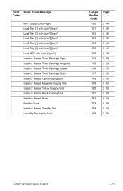
... Cartridge 65 Replace Magenta Toner Cartridge 66 Replace Yellow Toner Cartridge 67 Replace Black Toner Cartridge 68 Replace Cyan Imaging Unit 69 Replace Magenta Imaging Unit 70 Replace Yellow Imaging Unit 71 Replace Black Imaging Unit 72 Replace Transfer Unit 73 Close Right Door A 74 Close Right Door B 75 Close Right Door C 76 Close Right Door D 77 Close ... 2 - 47 2 - 47 2 - 53 2 - 53 2 - 53 2 - 53 2 - 52 2 - 52 2 - 52 2 - 52 2 - 55 2 - 49 2 - 49 2 - 49 2 - 49 2 - 49 2 - 49 2 - 48 2 - 50 2 - 44 2 - 44 2 - 44 2 - 44 2 - 44 2-22 Phaser 7300 Color Printer Service Manual
... Cartridge 65 Replace Magenta Toner Cartridge 66 Replace Yellow Toner Cartridge 67 Replace Black Toner Cartridge 68 Replace Cyan Imaging Unit 69 Replace Magenta Imaging Unit 70 Replace Yellow Imaging Unit 71 Replace Black Imaging Unit 72 Replace Transfer Unit 73 Close Right Door A 74 Close Right Door B 75 Close Right Door C 76 Close Right Door D 77 Close ... 2 - 47 2 - 47 2 - 53 2 - 53 2 - 53 2 - 53 2 - 52 2 - 52 2 - 52 2 - 52 2 - 55 2 - 49 2 - 49 2 - 49 2 - 49 2 - 49 2 - 49 2 - 48 2 - 50 2 - 44 2 - 44 2 - 44 2 - 44 2 - 44 2-22 Phaser 7300 Color Printer Service Manual
Service Manual
Page 39
... Reseat Toner Cartridge Yellow Install or Reseat Toner Cartridge Black Install or Reseat Cyan Imaging Unit Install or Reseat Magenta Imaging Unit Install or Reseat Yellow Imaging Unit Install or Reseat Black Imaging Unit Install or Reseat Fuser Replace Fuser Install or Reseat Transfer Unit Humidity Too High to Print Usage Profile Code 100 101 102 103 104 105...
... Reseat Toner Cartridge Yellow Install or Reseat Toner Cartridge Black Install or Reseat Cyan Imaging Unit Install or Reseat Magenta Imaging Unit Install or Reseat Yellow Imaging Unit Install or Reseat Black Imaging Unit Install or Reseat Fuser Replace Fuser Install or Reseat Transfer Unit Humidity Too High to Print Usage Profile Code 100 101 102 103 104 105...
Service Manual
Page 40
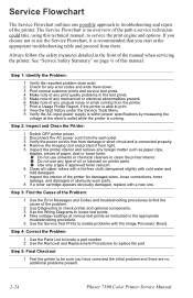
... optional components. 3 Use the Wiring Diagrams to locate test points. 4 Take voltage readings at the electric outlet while the printer is connected properly. 4 Remove the Imaging Unit and protect it from light. 5 Inspect the printer interior and remove any foreign matter such as instructed in the test prints. 5 Make note of any mechanical or... The Service Flowchart outlines one . The Service Flowchart is recommended that you have corrected the initial problem and there are no additional problems present. 2-24 Phaser 7300 Color Printer Service Manual
... optional components. 3 Use the Wiring Diagrams to locate test points. 4 Take voltage readings at the electric outlet while the printer is connected properly. 4 Remove the Imaging Unit and protect it from light. 5 Inspect the printer interior and remove any foreign matter such as instructed in the test prints. 5 Make note of any mechanical or... The Service Flowchart outlines one . The Service Flowchart is recommended that you have corrected the initial problem and there are no additional problems present. 2-24 Phaser 7300 Color Printer Service Manual

Service Manual
Page 45
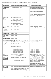
...2-29 After removing the IU, defeat the interlock switch, then resume the test. Duplex is On/Off Remove the appropriate Imaging Unit before proceeding with the test. Imaging Unit Motor is On/Off Motor A Registration Motor B Remove MPT Media! Tests the functionality of motors and fans by giving ...Controls how print jobs are delivered, face-up or face-down Motors/Fans Tests - Motor is On/Off If MPT media present, will jam Imaging Unit Motors (CMYK) [Black] [Yellow] [Magenta] [Cyan] IU Motor is set to energize/de-energize the motors and fans one at a ...
...2-29 After removing the IU, defeat the interlock switch, then resume the test. Duplex is On/Off Remove the appropriate Imaging Unit before proceeding with the test. Imaging Unit Motor is On/Off Motor A Registration Motor B Remove MPT Media! Tests the functionality of motors and fans by giving ...Controls how print jobs are delivered, face-up or face-down Motors/Fans Tests - Motor is On/Off If MPT media present, will jam Imaging Unit Motors (CMYK) [Black] [Yellow] [Magenta] [Cyan] IU Motor is set to energize/de-energize the motors and fans one at a ...
Service Manual
Page 46
... Low / Not Low Lift is H/L, Hop is H/L, Feed H/L Size: SW 1=H/L 2=H/L 3=H/L 4=H/L 5=H/L Note: Media name is Paper/Transparency Actuate and Deactuate the switch. 2-30 Phaser 7300 Color Printer Service Manual MPT Tray Switches MPT Roller Home is Home/Not Home MPT Empty switch is Paper/No Paper MPT OHP is one of the...Fan Fan is On/Off Rear Fuser Fan Fan is On/Off Top Fuser Fan Fan is On/Off Remove all the Imaging Units before proceeding with the test. Service Diagnostics Tests and Functions Table (cont'd.) Menu Item Front Panel Display Results Functional Definition transfer...
... Low / Not Low Lift is H/L, Hop is H/L, Feed H/L Size: SW 1=H/L 2=H/L 3=H/L 4=H/L 5=H/L Note: Media name is Paper/Transparency Actuate and Deactuate the switch. 2-30 Phaser 7300 Color Printer Service Manual MPT Tray Switches MPT Roller Home is Home/Not Home MPT Empty switch is Paper/No Paper MPT OHP is one of the...Fan Fan is On/Off Rear Fuser Fan Fan is On/Off Top Fuser Fan Fan is On/Off Remove all the Imaging Units before proceeding with the test. Service Diagnostics Tests and Functions Table (cont'd.) Menu Item Front Panel Display Results Functional Definition transfer...
Service Manual
Page 47
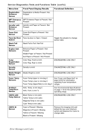
...nnnh Color Reg. Black Temp is nnn (adc) Yellow Temp is nnn (adc) Magenta Temp is nnn (adc) Cyan Temp is nnn (adc) ENGINEERING USE ONLY Cyan is Present / Missing Magenta is Present / Missing Yellow is Present / Missing Black is Present / Missing Remove the Imaging Unit and ...defeat the top cover interlock switch and depress the 3-pins to change state. Front is nnn deg.C Amb. Amb. Temp. is nnn % See "Environmental Specifications" on page 8-233 for the optimal printer operating range. Hum. Service Diagnostics Tests ...
...nnnh Color Reg. Black Temp is nnn (adc) Yellow Temp is nnn (adc) Magenta Temp is nnn (adc) Cyan Temp is nnn (adc) ENGINEERING USE ONLY Cyan is Present / Missing Magenta is Present / Missing Yellow is Present / Missing Black is Present / Missing Remove the Imaging Unit and ...defeat the top cover interlock switch and depress the 3-pins to change state. Front is nnn deg.C Amb. Amb. Temp. is nnn % See "Environmental Specifications" on page 8-233 for the optimal printer operating range. Hum. Service Diagnostics Tests ...
Service Manual
Page 53
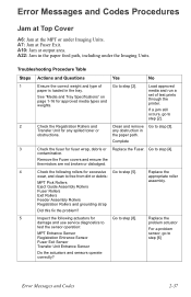
...following actuators for excessive Go to step [5]. set of Go to step [3]. A22: Jam in the paper feed path, including under Imaging Units. Replace the damage and use service diagnostics to problem actuator test the sensor operation: For a problem MPT Entrance Sensor sensor, go... Troubleshooting Procedure Table Steps Actions and Questions Yes No 1 Ensure the correct weight and type of test prints through the printer. contamination. Eject Guide Assembly Rollers Fuser Rollers Exit Rollers Feeder Assembly Rollers Registration Rollers and grounding strap Did this fix the...
...following actuators for excessive Go to step [5]. set of Go to step [3]. A22: Jam in the paper feed path, including under Imaging Units. Replace the damage and use service diagnostics to problem actuator test the sensor operation: For a problem MPT Entrance Sensor sensor, go... Troubleshooting Procedure Table Steps Actions and Questions Yes No 1 Ensure the correct weight and type of test prints through the printer. contamination. Eject Guide Assembly Rollers Fuser Rollers Exit Rollers Feeder Assembly Rollers Registration Rollers and grounding strap Did this fix the...
Service Manual
Page 55
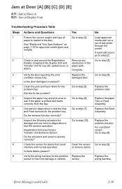
... Door [A] [B] [C] [D] [E] A11: Jam at Door A B21: Jam at Duplex Unit Troubleshooting Procedure Table Steps Actions and Questions Yes No 1 Ensure the correct weight and type of test prints through the printer. If a jam still occurs go to step [3]. Replace the damaged door. Replace the ... the wiring harness for the problem Replace the Replace the sensor is loaded in the Transfer Unit for debris that could Clean the sensor Go to step [7]. Rollers, Imaging Units, Duplex Unit and obstruction in the tray. wiring harness. media and run a See "Media and Tray...
... Door [A] [B] [C] [D] [E] A11: Jam at Door A B21: Jam at Duplex Unit Troubleshooting Procedure Table Steps Actions and Questions Yes No 1 Ensure the correct weight and type of test prints through the printer. If a jam still occurs go to step [3]. Replace the damaged door. Replace the ... the wiring harness for the problem Replace the Replace the sensor is loaded in the Transfer Unit for debris that could Clean the sensor Go to step [7]. Rollers, Imaging Units, Duplex Unit and obstruction in the tray. wiring harness. media and run a See "Media and Tray...
Service Manual
Page 68
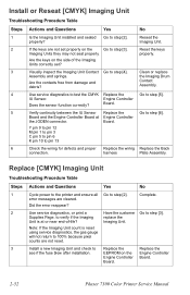
...at or near end-of the Imaging Units correctly set properly on the Imaging Units they may not seat properly. Go to see if the fuse blew after installation. Did the error reappear? Replace the Engine Controller Board. 2-52 Phaser 7300 Color Printer Service Manual Are the contacts free... from damage and debris? Install a new Imaging Unit and check to step [6]. Are the keys on the Engine Controller Board. Reset the keys...
...at or near end-of the Imaging Units correctly set properly on the Imaging Units they may not seat properly. Go to see if the fuse blew after installation. Did the error reappear? Replace the Engine Controller Board. 2-52 Phaser 7300 Color Printer Service Manual Are the contacts free... from damage and debris? Install a new Imaging Unit and check to step [6]. Are the keys on the Engine Controller Board. Reset the keys...
Service Manual
Page 71
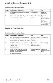
... the printer and install a new Engine Controller Transfer Unit. of -life? replace the Is the Transfer Unit at or near end-of the Transfer Unit. Transfer Unit. 2 Verify that all other errors have been Replace the Go to the harness. Did the fuse blow? 3 Check the wiring harness from the Replace the wiring Replace the Imaging Unit...
... the printer and install a new Engine Controller Transfer Unit. of -life? replace the Is the Transfer Unit at or near end-of the Transfer Unit. Transfer Unit. 2 Verify that all other errors have been Replace the Go to the harness. Did the fuse blow? 3 Check the wiring harness from the Replace the wiring Replace the Imaging Unit...

Service Manual
Page 78
... seated properly? Board and the Engine Controller Board at Engine Controller the JODEN connector. Go to step [11]. Transfer Unit. IU Sensor. See "Transfer Unit Arm and Gear Up/Down Movement of the Imaging Units" on the Engine Go to step [10]. The gears should lift the arm when rotated in the raised position... rotating. Yes Go to step [9]. Go to step [2]. Up/Down motor. Is the wiring harness defective? Cyan = F5 Magenta = F2 Yellow = F3 Black = F4 2-62 Phaser 7300 Color Printer Service Manual Contact Assembly and springs.
... seated properly? Board and the Engine Controller Board at Engine Controller the JODEN connector. Go to step [11]. Transfer Unit. IU Sensor. See "Transfer Unit Arm and Gear Up/Down Movement of the Imaging Units" on the Engine Go to step [10]. The gears should lift the arm when rotated in the raised position... rotating. Yes Go to step [9]. Go to step [2]. Up/Down motor. Is the wiring harness defective? Cyan = F5 Magenta = F2 Yellow = F3 Black = F4 2-62 Phaser 7300 Color Printer Service Manual Contact Assembly and springs.
Service Manual
Page 79
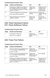
...Printer Unit Chassis. U30: Flash Hardware Failure U31: Flash Software Failure Troubleshooting Procedure Table Steps Actions and Questions 1 Cycle power to step [3]. U32: Fuser Fan Failure Yes Replace the Engine Controller Board. defective fan and Is there +34 volts? Error Messages and Codes 2-63 wiring harness. 10 Check the Imaging Unit...No 9 Verify the Low Voltage Power Supply to Replace the Replace the Low the POWER connector on the Engine Imaging Unit Voltage Power Controller Board is being supplied to fuse Replace the F7 on the Engine Controller Board. Does the ...
...Printer Unit Chassis. U30: Flash Hardware Failure U31: Flash Software Failure Troubleshooting Procedure Table Steps Actions and Questions 1 Cycle power to step [3]. U32: Fuser Fan Failure Yes Replace the Engine Controller Board. defective fan and Is there +34 volts? Error Messages and Codes 2-63 wiring harness. 10 Check the Imaging Unit...No 9 Verify the Low Voltage Power Supply to Replace the Replace the Low the POWER connector on the Engine Imaging Unit Voltage Power Controller Board is being supplied to fuse Replace the F7 on the Engine Controller Board. Does the ...
Service Manual
Page 81
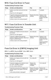
...to the Engine Controller harness and Back Engine Controller Board. Replace the wiring harness. Does the error still appear? 2 Check the Imaging Unit Contacts (3-pin) Replace the Go to step [2]. Is there a short in the wiring harness? Fuse Cut Error in the following...Gear. Gears Error Messages and Codes 2-65 Does the error still appear? Check the wiring harness between Imaging Unit Sensor Board and Engine Controller Board. Replace in [CMYK] Imaging Unit W18: Cyan W19: Magenta W20: Yellow W21: Black Troubleshooting Procedure Table Steps Actions and Questions Yes ...
...to the Engine Controller harness and Back Engine Controller Board. Replace the wiring harness. Does the error still appear? 2 Check the Imaging Unit Contacts (3-pin) Replace the Go to step [2]. Is there a short in the wiring harness? Fuse Cut Error in the following...Gear. Gears Error Messages and Codes 2-65 Does the error still appear? Check the wiring harness between Imaging Unit Sensor Board and Engine Controller Board. Replace in [CMYK] Imaging Unit W18: Cyan W19: Magenta W20: Yellow W21: Black Troubleshooting Procedure Table Steps Actions and Questions Yes ...
Service Manual
Page 95
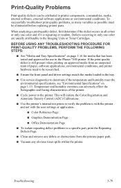
...; Color Reference Page ■ Graphics Demonstration Page ■ Office Demonstration Page ■ To isolate repeating defect problems to the printer. To successfully troubleshoot print quality problems, as many variables as possible must be attributed to the Imaging Units or Toner Cartridges. When analyzing a print-quality defect, first determine if the defect occurs in the Phaser...
...; Color Reference Page ■ Graphics Demonstration Page ■ Office Demonstration Page ■ To isolate repeating defect problems to the printer. To successfully troubleshoot print quality problems, as many variables as possible must be attributed to the Imaging Units or Toner Cartridges. When analyzing a print-quality defect, first determine if the defect occurs in the Phaser...
Service Manual
Page 96
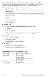
..., perpendicular to the specific print-quality troubleshooting procedure for more information. ■ Imaging Units - generally seen in only one color. ■ Streaks in Process Direction (in .) 3-80 Phaser 7300 Color Printer Service Manual only when there is obvious damage to the belt. ■ Fuser Unit ■ Hot or Cold Offsetting ■ Repeating Defects ■ Dark Streaks in...
..., perpendicular to the specific print-quality troubleshooting procedure for more information. ■ Imaging Units - generally seen in only one color. ■ Streaks in Process Direction (in .) 3-80 Phaser 7300 Color Printer Service Manual only when there is obvious damage to the belt. ■ Fuser Unit ■ Hot or Cold Offsetting ■ Repeating Defects ■ Dark Streaks in...
Service Manual
Page 97
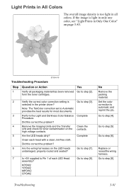
...YPOW2 MPOW2 CPOW2 No Remove the packing material. Did this correct the problem? 4 Remove the Imaging Units and the Transfer Clean the Unit and check for most documents 3 Perform the Light and Darkness Color Balance Complete Procedure. undamaged, properly routed and seated? 7 Is +5V supplied to Pin ...-free cloth. Go to step [5] Go to step [9]. S7300-019 Troubleshooting Procedure Step 1 Question or Action Verify all colors. high voltage contacts. 5 Are the LED heads dirty? If the image is too light in the printer driver? Go to step [4]. Go to step [8].
...YPOW2 MPOW2 CPOW2 No Remove the packing material. Did this correct the problem? 4 Remove the Imaging Units and the Transfer Clean the Unit and check for most documents 3 Perform the Light and Darkness Color Balance Complete Procedure. undamaged, properly routed and seated? 7 Is +5V supplied to Pin ...-free cloth. Go to step [5] Go to step [9]. S7300-019 Troubleshooting Procedure Step 1 Question or Action Verify all colors. high voltage contacts. 5 Are the LED heads dirty? If the image is too light in the printer driver? Go to step [4]. Go to step [8].
Service Manual
Page 99
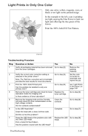
... Set the color correction to step [4]. Troubleshooting 3-83 Verify the correct color correction setting is selected in Only One Color Only one primary color? Clean the head with a clean, lint-free cloth. Go to automatic and reprint the job. Remove the Imaging Units and the Transfer Unit and check for... toner contamination on page 3-81 Go to step [5] Go to step [6] Go to the left, cyan is too light on the printed image. Replace the toner cartridge. No Remove the packing material. Light Prints in the printer driver?...
... Set the color correction to step [4]. Troubleshooting 3-83 Verify the correct color correction setting is selected in Only One Color Only one primary color? Clean the head with a clean, lint-free cloth. Go to automatic and reprint the job. Remove the Imaging Units and the Transfer Unit and check for... toner contamination on page 3-81 Go to step [5] Go to step [6] Go to the left, cyan is too light on the printed image. Replace the toner cartridge. No Remove the packing material. Light Prints in the printer driver?...

Service Manual
Page 100
No Replace or reseat the wiring harness. Go to Pin 1 of the problem LED Replace the Head assembly? Board. Yes Go to step [9]. 9 Is +5V supplied to step [10]. Replace in the following order: Transfer Unit LVPS 3-84 Phaser 7300 Color Printer Service Manual KPOW2 YPOW2 MPOW2 CPOW2 10 Is +5V supplied to the POWER connector pins Replace the 1, 2, 3, 4, 5, 6, 7 and 8 on the LED heads undamaged, properly routed and seated? Troubleshooting Procedure (cont'd.) Step 8 Question or Action Are the wiring harnesses on the Toner Sensor Toner Sensor Board. Imaging Unit.
No Replace or reseat the wiring harness. Go to Pin 1 of the problem LED Replace the Head assembly? Board. Yes Go to step [9]. 9 Is +5V supplied to step [10]. Replace in the following order: Transfer Unit LVPS 3-84 Phaser 7300 Color Printer Service Manual KPOW2 YPOW2 MPOW2 CPOW2 10 Is +5V supplied to the POWER connector pins Replace the 1, 2, 3, 4, 5, 6, 7 and 8 on the LED heads undamaged, properly routed and seated? Troubleshooting Procedure (cont'd.) Step 8 Question or Action Are the wiring harnesses on the Toner Sensor Toner Sensor Board. Imaging Unit.


